

Water Process Solutions ENCORE 700 Operation & Maintenance Manual
ENCORE
®
700
PLUNGER METERING PUMP
Operation & Maintenance Manual

ENCORE 700 PLUNGER PUMP
Encore® Plunger Metering Pump
IM.ENC.PLUNGER
Unit 10
Mill Hall Business Estate
Aylesford
Kent
ME20 7JZ
UK
+44 (0) 1622 719945
www.waterprocesssolutions.com
enquiries@waterprocesssolutions.com
ISSUE 2 - 18/8/2016

Unit 10
Mill Hall Business Estate
Aylesford
Kent
ME20 7JZ
www.waterprocesssolutions.com
Phone: +44 (0) 1622719945
email: enquiries@waterprocesssolutions.com
Directives covered by this declaration
89/336/EEC Electromagnetic Compatibility Directive, amended by 92/31/EEC & 93/68/EEC
73/23/EEC Low Voltage Equipment Directive, amended by 93/68/EEC
89/392/EEC Machinery Directive, amended by 91/368/EEC, 93/44/EEC & 93/68/EEC
Products Covered by this declarat ion
ENCORE® 700 Plunger Metering Pumps [6P, 12P, 24P and 32P]
The products identified above comply with the requirements of the EMC Directive and with the principle elements of
the safety objectives of the Low Voltage and Machinery Directives. The following standards have been applied:
EMC Emissions:
EMC Immunity:
Electrical Safety:
Machinery Safety:
The CE mark was first applied in 1996
EC-DECLARATION OF CONFORMITY
EN 50 081 Parts 1 & 2
EN 50 082 Parts 1& 2
EN 60034
BS EN 292
BS EN 294
Date of Declaration: 09/02/99
.......................................................
C.B. Dean
Managing Director

ENCORE 700 PLUNGER PUMP
PLEASE NOTE: THIS EQUIPMENT HAS BEEN DESIGNED TO PROVIDE
RELIABLE SERVICE. HOWEVER BEFORE ATTEMPTING TO INSTALL,
OPERATE OR SERVICE THE EQUIPMENT, THIS INSTRUCTION MANUAL
SHOULD BE READ, UNDERSTOOD AND OBSERVED. FAILURE TO D0 SO
CAN RESULT IN IMPROPER OPERATION WITH POSSIBLY HAZARDOUS
RESULTS.
INTRODUCTION
This book provi des installat ion, operating and maintenance ins tructions for t he Encore
Plunger Meterin g Pumps; here -in-after refe rred to as the pum p or meteri ng pump. The
pump provides accurate metering and transfer of a wide variety of chemicals. It is
available in fo ur head s izes, f our gear r atios, di rect or pulley dr ive con figuratio ns and a
single and double simplex configuration. A non-loss-of motion, stroke adjustment is
used to vary the stroke for a more smooth pumping action. Non-loss-of motion is
achieved through t he use of a vari able eccentric mec hanism. Stroke a djustment is done
either manually or with an optional electric stroke length positioner.
An optional vari able speed dri ve controls dri ve motor spee d variations thro ugh signals
received from external sources.
When an electri c s troke le ngth pos iti oner or va ri able spe ed dr ive is use d wit h the p ump,
a separate instruction manual covering the particular equipment used will be furnished.
WARNING
: TO AVOID POSSIBLE SEVERE PERSONAL INJURY OR DAMAGE
TO THE EQUIPMENT, THIS EQUIPMENT SH0ULD BE INSTALLED,
OPERATED AND SERVICED ONLY BY TRAINED, QUALIFIED PERSONNEL
WHO ARE THOROUGHLY FAMILIAR WITH THE ENTIRE CONTENTS OF THIS
INSTRUCTION BOOK. WHEN DEALING WITH HAZARDOUS MATERIAL, IT IS
THE RESPONSIBILITY OF THE EQUIPMENT USER TO BECOME FAMILIAR
WITH THE SAFETY PRECAUTIONS LISTED IN THE SAFETY SUMMARY ON
PAGES X & Y AND FOLLOW ALL SAFETY PRECAUTIONS RECDMMENDED
BY THE MATERIAL MANUFACTURER / SUPPLIER. AVOID CONTACTING
ELECTRICALLY HOT METER POSTS AND CIRCUIT BOARD COMPONENTS
WHILE MAKING METER ADJUSTMENTS.
When submitting c orrespon dence or ordering m ate rial, alw ays speci fy model a nd serial
number of equipment.

ENCORE 700 PLUNGER PUMP
GUARANTEE & WARRANTY
Water Process Solutions Ltd (WPS) guarantees that equipment manufactured or
represented by the Company is free fr om defect in workmanship and materials under
normal use and s ervice. The Company w ill make good, by repai r, or at its option, b y
replacement, de fects which, unde r proper use, in the Company's o pinion, appea r in the
equipment within a period of 12 months after shipment by the Company from our
works. The Company's responsibility is limited to the replacement of defective parts
whether the work is carried out on site or at the Company's works.
Equipment will be repai red under guar antee , free of char ge, at our works providi ng that
it is returned t o the C ompa ny, freight paid. A lter natively, any nec essary re pairs m ay be
carried out on site provi ding that a ny travel a nd acc ommodation c osts inc urred ar e paid
at ruling rates. S hould the Company be calle d to carry out work under guara ntee and
find that the faul t lies outs ide the Com pany's r esponsi bility, t hen any c ost invol ved will
be charged to the Purchaser's account.
This guarantee i s in lie u of a ll othe r gua ra ntee s and wa rr antie s e xpre ssed or im plie d and
does not apply to replacement or repairs which are required as a result of improper
installation, misuse, maladjustment, modification or lack of routine maintenance by
others. The Company does not guarantee the overall performance of any plant or the
result of any process on which the Company's equipment is used.
Equipment included which is not manufactured or represented by the Company is
specificall y exclude d from the obliga tion g iven above. S uch equi pme nt wil l be re paire d
or replaced under guarantee only to the guarantee (if any) which the Company may
have receive d from the supplier or manufacture r of such equipme nt in respect thereof,
but not so as to impose on the Compa ny in r esp ect of such equi pme nt a l iabilit y grea ter
than that set out herein.
The guarantee does not extend to, and the Company accepts no liability for,
consequential se condary damages or losses of any kind susta ined directly or indirectly
as a result of a defect in any products, materials or installation.
NOTE
Minor part numbe r changes ma y be incorporat ed into WPS prod ucts from time to time
that are not immediately reflecte d in the Instruction Book. If such a c hange apparentl y
has been made in your equipment and does not appear to be reflected in your
Instruction Book, contact WPS for information.
Please include the equipment serial number in all correspondence. It is essential for
effective communication and proper equipment identification.

ENCORE 700 PLUNGER PUMP
TABLE OF CONTENTS
Reordering of Preventive Maintenances Kits PM-1
Very Important Safety Precautions SP-1
Protective Equipment and Clothing SP-2
Technical Data Section 1
Installation Section 2
Operation Section 3
Service Section 4
Illustrations Section 5

ENCORE 700 PLUNGER PUMP
PM -1 : Preventive Maintenance
Protect Your Equipment Investment
Minimize Downtime
Reorder a Preventive Maintenance Kit Now. Keep One On Hand
Quality
+ Preventive = Dependable Operation
Equipment
Maintenance
Minimum Downtime
There's no question about it
Equipment that is properly maintained is dependable equipment.
It will give optimum performance with minimum unscheduled downtime.
WPS manufactures quality equipment designed for performance and reliability. Each
product is car e f ully tested and inspected before s hi pm e nt, to ensure tha t it m e e t s our high
standards.
Our equipment is e nginee red for ea sy mainte nance. To e nsure ma ximum ser vice life a nd
minimize unscheduled repairs, we recommend a program of regular preventive
maintenance, as described in the Ser vice section of this b ook. To support this program,
we developed sta ndard service kits. These kits’s can also be use d for minor emergency
repairs to minimize downtime.
We recommend that these kits be available in your stock at all times. When the complete
kit or any of its pads are used, the kit should be replaced immediately.
Preventive maint enance kits may be orde red directly from t he company which supplied
your equipment, or the y m ay be orde red direc tly from WPS. For or deri ng numbe rs, re fer
to the parts list at the rear of this book.

ENCORE 700 PLUNGER PUMP
PREVENTIVE MAINTENANCE SCHEDULE AND RECORD OF
PERFORMANCE
This equipment s hould receive sche duled preventive maintenance on a one year cycle*.
It is recommended that the following table be used to plan, schedule and record this
important work.
DATE OF INSTALLATION
PREVENTIVE MAINTENANCE LOG
SCHEDULE DATE
DATE PERFORMED
*NOTE: This is the recommended cycle. Your local operating conditions may call for
more frequent preventive maintenance.

ENCORE 700 PLUNGER PUMP
SP-1: VERY IMPORTANT SAFETY PRECAUTIONS
This page, titled " Very Important Safety Pre cautions "provide s, in brief, information of
urgent importance relative to SAFETY, INSTALLATION, OPERATION, and
MAINTENANCE of this equipment.
WARNING
TO AVOID POSSIBLE SEVERE PERSONAL INJURY OR EQUIPMENT DAMAGE,
OBSERVE THE FOLLOWING:
THIS EQUIPMENT SHOULD BE INSTALLED, OPERATED AND SERVICED
ONLY BY TRAINED, QUALIFIED PERSONNEL WHO ARE THOROUGHLY
FAMILIAR WITH THE ENTIRE CONTENTS OF THIS INSTRUCTION BOOK.
AV0ID CONTACTING ELECTRICALLY HOT METER POSTS AND CIRCUIT
BOARD COMPONENTS WHILE MAKING METER ADJUSTMENTS.
WHEN DEALING WITH HAZARDOUS MATERIAL, IT IS THE RESPONSIBILITY
OF THE EQUIPMENT USER TO OBTAIN AND FOLLOW ALL SAFETY
PRECAUTIONS RECOMMENDED BY THE MATERIAL MANUFACTURER /
SUPPLIER.
CONSULT YOUR WPS REPRESENTATIVE IF THE PUMP IS TO BE USED
UNDER CONDITIONS OTHER THAN ORIGINALLY SPECIFIED AND IF THERE
IS ANY QUESTION REGARDING THE SIZE OF THE DISCHARGE LINE.
USE RIGID PIPE WHEN HAZARDOUS CHEMICALS ARE PUMPED AND / OR
ELEVATED PRESSURE / TEMPERATURES ARE ENCOUNTERED.
USE EXTREME CARE TO AVOID CONTACT WITH THE MATERIAL AND
POSSIBLE SEVERE PERSONAL INJURY. CONSULT YOUR CHEMICAL
SUPPLIER FOR INSTRUCTIONS IN THE PREPARATION OF SOLUTIONS AND
THE HANDLING OF CHEMICALS. OBSERVE ALL RECOMMENDED SAFETY
PRECAUTIONS.
DO NOT SPILL SOLUTION. IF ANY SOLUTION IS SPILLED, DILUTE OR WASH
AWAY WITH WATER IMMEDIATELY OR FOLLOW SUPPLIER'S
INSTRUCTIONS FOR HAZARDOUS MATERIALS.
AVOID BEING SPRAYED WITH LIQUID UNDER PRESSURE. PRIOR TO
DISASSEMBLY OF PPPE CONNECTIONS REFER TO DETAILED
INSTRUCTIONS ON RELIEVING PRESSURE AND DRAINING. ALLOW
SYSTEM TO DRAIN FULLY BEFORE ATTEMPTING TO DISASSEMBLE PIPING
AND REMOVING VALVES AND / OR HEAD.

ENCORE 700 PLUNGER PUMP
SINCE THE STORAGE AND HANDLING OF SODIUM CHLORITE PRESENTS
VERY SPECIFIC HAZARDS, THE USER MUST SEEK THE ADVICE Of HIS
SUPPLIER WlTH REFERENCE TO STORAGE FACILITIES, HANDLING
PRECAUTIONS AND HEALTH HAZARDS.
SODIUM CHLORITE, WHEN FINELY DIVIDED IN THE PRESENCE OF
ORGANIC COMPOUNDS, IS A POSSIBLE FIRE HAZARD. FOR THIS REASON,
EXTREME CARE MUST BE EXERCISED TO PREVENT SOLUTIONS FROM
DRYING OUT IN THE THREADED PORTIONS OF THE PUMP BODY AND
RELATED PARTS. OBSERVE CAREFULLY THE MANUFACTURER /
SUPPLIERS RECOMMENDED SAFETY PROCEDURES AND THE HANDLING
AND STORAGE PROCEDURES IN THIS BOOK.
WHEN SERVICING HEADS FOR DISASSEMBLY AND / OR VALVES, FOLLOW
PROCEDURES IN THE SECTION FOR DISASSEMBLY.
USE EXTREME CARE TO AVOID CONTACT WITH THE MATERIAL AND
POSSIBLE SEVERE PERSONAL INJURY. WHEN USING HAZARDOUS
MATERIAL, OBSERVE ALL SAFETY PRECAUTIONS RECOMMENDED BY THE
MATERIAL MANUFACTURE / SUPPLIER. USE APPROPRIATE PROTECTIVE
CLOTHING AND EYE PROTECTION WHEN HANDLING HAZARDOUS
MATERIAL.
USE EXTREME CARE TO AVOID CONTACT WITH LIQUID PRESENT IN HEAD.
ALLOW SUCTION VALVE TO FALL INTO SUITABLE CONTAINER AND
CATCH LIQUID,
USE EXTREME CARE TO AVOID CONTACT BECAUSE LIQUID IS PRESENT
BETWEEN DISCHARGE DRAIN VALVE AND UNION ELBOW. FLUSH SPILLED
LIQUID IMMEDIATELY.
TURN POWER OFF BEFORE SERVICING.
DO NOT RUN THE PUMP WITH THE BELT GUARD REMOVED,
USE ONLY WPS LISTED PARTS EXCEPT FOR COMMERCIALLY AVAILABLE
PARTS WHICH ARE IDENTIFIED BY COMPLETE DESCRIPTION ON PARTS
LIST. THE USE OF UNLISTED PARTS CAN RESULT IN EQUIPMENT
MALFUNCTIONS HAVING HAZARDOUS CONSEQUENCES.
THIS EQUIPMENT SHOULD BE INSTALLED, OPERATED AND SERVICED
ONLY BY TRAINED, QUALIFIED PERSONNEL, WHO ARE THOROUGHLY
FAMILIAR WITH THE ENTIRE CONTENTS OF THE INSTRUCTION BOOK.
DO NOT DISCARD THIS INSTRUCTION BOOK UPON COMPLETION OF
INSTALLATION. INFORMATION PROVIDED IS ESSENTIAL TO PROPER &

ENCORE 700 PLUNGER PUMP
SAFE OPERATION AND MAINTENANCE.
ADDITIONAL OR REPLACEMENT COPIES OF THIS INSTRUCTION BOOK ARE
AVAILABLE FROM:
Unit 10
Mill Hall Business Estate
Aylesford
Kent
ME20 7JZ
UK
NOTE
Minor part numbe r changes may be incor porated into WPS product s from time to time
that are not immediately reflected in the instruction book. If such a change has
apparently been made in our equipment and does not appear to be reflected in your
instruction book, contact your local WPS Sales Office for information.
Please include t he equipment serial number in all correspondence. It i s essential for
effective communication and proper equipment identification.

ENCORE 700 PLUNGER PUMP
SP-2: NOTES ON PROTECTIVE EQUIPMENT AND CLOTHING.
The following War ning appears in se veral locations in this book. It is general in nature
due to the variety of hazardous liquids this pump is capable of handling.
WARNING: WHEN DEALING WITH HAZARDOUS MATERIAL,
IT IS THE RESPONSIBILITY OF THE EQUIPMENT USER TO OBTAIN AND
FOLLOW ALL SAFETY PRECAUTIONS RECOMMENDED BY THE MATERIAL
MANUFACTURER / SUPPLIER.
It is good genera l practice to make use of the foll owing types of protective equipment
when handling any hazardous liquid.
IT IS RECOMMENDED THAT SUCH PROTECTIVE EQUIPMENT BE USED BY
ALL PERSONS SERVICING THIS PUMP, ASSOCIATED PIPING, TUBING,
VALVES, AND ACCESSORIES, WHEN THE PUMP IS HANDLING ANY
HAZARDOUS LIQUID.
1. Goggles, flexible fitting, hooded ventilation
2. Face Shield
3. Chemical Apron
4. Chemical Gloves

ENCORE 700 PLUNGER PUMP
SECTION 1 - TECHNICAL DATA
Pump Type
Variable Eccentric, Plunger type metering
pump. Simplex, Duplex and double
Simplex capabilities
Plunger / Gland
Ceramic Plunger, PTFE / Glass chevron
packing. Single or double chevrons
Service
Metering of mild to very corrosive (water
like viscosity) chemicals.
Drive Unit
Directly coupled or pulley coupled motor.
Four stroking speeds 30,60,120,144SPM
Variable Speed
AC and DC speed control available.
Capacity Range
Up to 145 l/hr with single head.
Pressure Range
Up to 200 BAR. Refer to chart for
additional information.
Stroke length
10 turn stroke control. Adjustable over
10:1 range.
Accuracy
+/- 1% full scale over 10:1 range under
constant suction and discharge conditions.
Suction Lift
Up to 1M water lift
Motor Voltage
240 VAC, 50 Hz, 1 ph
415 VAC, 50 Hz, 3 ph
Ambient temperature limits
35-125 degF (2 -52 degC)
Lubrication
Gear oil, SAE90 with antifoam agent or
shell OMALA
Weight
50 kg (110 ibs) – average.

ENCORE 700 PLUNGER PUMP
1.2 Material Identification / Composition
The chemical composition of materials (these include optional variabl e mater ials) used in
the manufacture of the Metering Pump are listed in Table 1.2 below.
Common Term
Composition
Ceramic
99% Aluminium Oxide
Hypalon
A Chlorosulphonated polyethylene
Kynar (PVDF)
Polyvinylidene fluoride
Stainless 316
AISI 316 – Cr 16 -18%
Ni 10 -14 %, C 0.08%, Mn 2%
Si 1%, P 0.045%, S 0.03%
Mo 2-3%
TFE
Fluorocarbon resin of tretrafluoroethylene
polymer
Viton
Copolymer of vinylidene and
perfluoropropylene or hexafluoropropylene
PVC
Polyvinyl Chloride
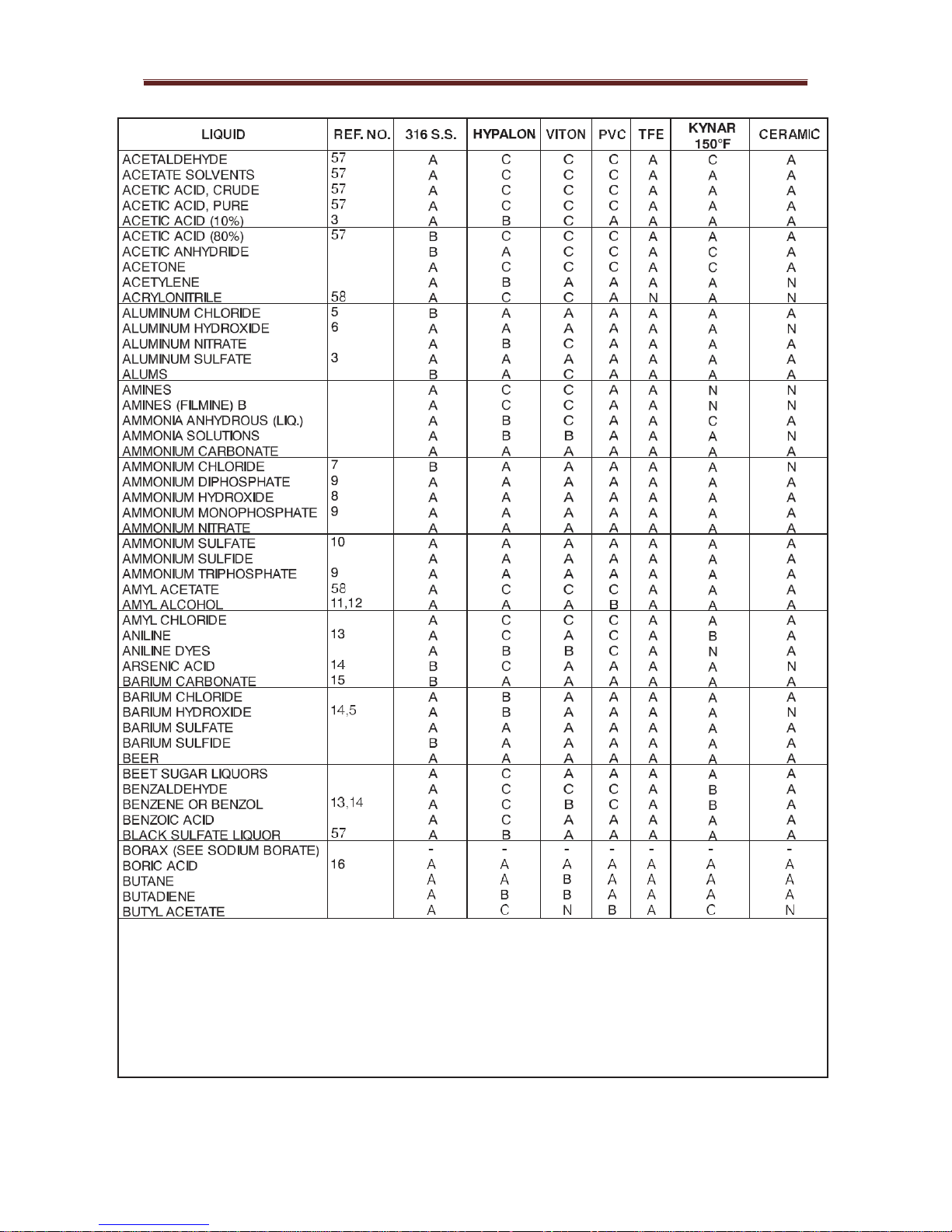
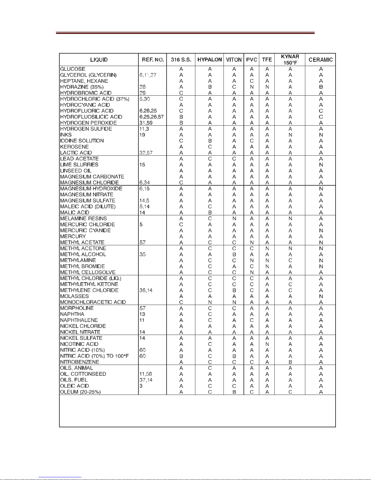
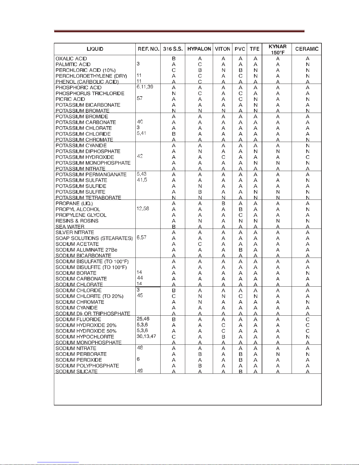
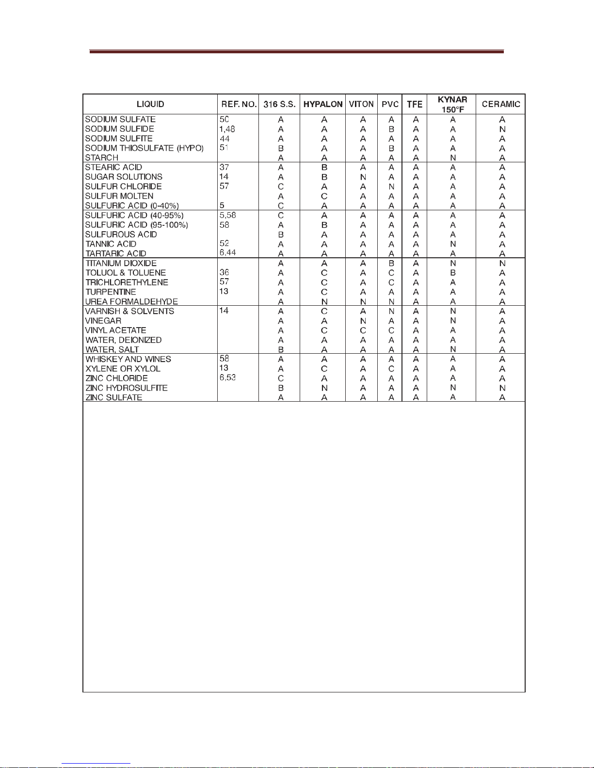
1.3 PUMP COMPATIBILITY
The compatibility of the Encore Plunger Metering Pump with various liquid materials
are listed in Dwg. 440.050.190.010A-F located at the end of this section. The table
identifies the various materials that can enter and come in contact with component
materials in the wetted end of the pump and its effect on pump performance.
ENCORE 700 PLUNGER PUMP

ENCORE 700 PLUNGER PUMP
440.050.190.010A-F
ENCORE 700 PLUNGER PUMP
440.050.190.010A-F
440.050.190.010A-F
ENCORE 700 PLUNGER PUMP
ENCORE 700 PLUNGER PUMP
440.050.190.010A-F
440.050.190.010A-F

ENCORE 700 PLUNGER PUMP
1. WARNING: DRIED RESIDUE OF SPILLED
30.
HYPALON TO 130°F
SOLUTIONS IS EXPLOSIVE.
31.
PVC TO 100°F, 50%, SS TO 100°F, 50%
3. SS TO180°F 32.
PVC TO 70°F, 10%, SS TO 70°F, 10%
5. PVC TO 125°F
34.
SS TO 70°F, 5%, PVC 125°F SAT
6. HYPALON TO 180°F
35.
PVC TO 100°F, SS TO 70°F
7. SS TO 125°F 10%, PVC TO 125°F
36.
VITON TO 100°F
8. PVC TO 125°F, 29%, SS TO 180°F, 29%
37.
HYPALON TO 150°F
9. SS TO 70°F, 5%
38.
SS TO 70°F, 10%
10. PVC TO 105°F, 40%, SS TO 180°F SAT
39.
PVC TO 125°F, 80%, SS TO 70°F, 80%
11. VITON TO 180°F
40.
PVC TO 100°F, SAT, SS TO 180°F, 50%
12. PVC TO 100°F PURE
41.
SS TO 180°F, 5%
13. VITON TO 158°F
42.
PVC TO 70°F, 50% OR TO 125°F, 30%, SS TO
14. SS TO 140°F
180°F, 50%
15. USE SLURRY VALVES
43.
SS TO 140°F, 10%
16. PVC TO 105°F, SS TO 180°F
44.
SS TO 180°F, 50%
17. PVC TO 100°F, SS TO 100°F
45.
PVC TO 105°F
18. SS TO 70°F DILUTE, PVC TO 125°F
46.
PVC TO 125°F, 4%, SS TO 70°F, 5%
19. PVC TO 100°F, 50%, SS TO 70°F, 5%
47.
PVC TO 125°F, 15%, SS TO 70°F, 5%
20. PVC TO 100°F, 25%, SS TO 180°F, 50%
48.
SS TO 125°F
21. PVC TO 100°F, SS TO 160°F
49.
PVC TO 125°F, 41 Be, SS TO 140°F, 41 Be
22. VITON TO 120°F
50.
PVC TO 125°F, 30%
24. PVC TO 125°F, 36%, SS TO 180°F 10%
51.
PVC TO 125°F, 50%, SS TO 70°F, 50%
25. FLUORIDATION REQUIRES AN ANTI-SYPHON
52.
PVC TO 100°F, 10%, SS TO 150°F
PUMP INSTALLATION CONSULT LOCAL REGU-
53.
PVC TO 100°F, SS TO 180°F, 70%
LATIONS FOR DETAILS.
57.
KYNAR TO 70°F
26. PVC TO 30%
58.
KYNAR TO 120°F
27. PVC TO 125°F, 50%, SS TO 70°F, 5%
59.
KYNAR TO 120°F, 30%
28. MAY CAUSE SURFACE PITTING TO SS
60.
KYNAR TO 100°F
29. PVC TO 125°F, 48%

ENCORE 700 PLUNGER PUMP
SECTION 2 - INSTALLATION
LIST OF CONTENTS
General Information 2.1
Unpacking 2.2
Mounting the Pump 2.3
Pipe Line Diameter 2.4
Plunger Size Pressure Rating 2.5
Installation 2.6
Illustrations
440.050.190.010A-F
Typical Installation - Simplex Manual Arrangement 440.400.1-PLUNGER
Typical Installation - Double Simplex Manual Arrangement 440.400.2-PLUNGER
Typical Installation - Duplex Manual Arrangement 440.400.2B-PLUNGER
Typical Installation - Suction Lift 440.400.3-PLUNGER
Typical instal la ti o n - Flooded Suction 440.400.4-PLUNGER
Installation Wiring 440.400.5-PLUNGER
2.1 GENERAL INFORMATION
To provide satisfactory service, the Encore metering pump must be installed properly in accorda nce
with the following instructions. These instructions must be followed or operational difficulties, lack of
accuracy and possible damage to the pump mechanism may occur.
2.2 UNPACKING
When unpacking, check all items against the packing list to be sure no parts are missing or discarded
with the packing material. Wherever possible, unpack the pump at the installation site.
2.3 MOUNTING THE PUMP
Pump location is important to the operation of the pump. Select a place that is dry and provides a level
base for the pump. Allow work space around the pump for inspection, adjustments and servicing. Be
sure it is near a power supply and located where the discharge line may be conveniently run to the
point of application.
It is recommended that the pump be installed with a flooded suction (see Dwg 440.400.4-PLUNGER).
A carefully considered and correct installation will help provide satisfactory performance.
When installing the equipment, proceed as follows:
a. Select the appropriate dimension and / or installation drawing to be sure the location
selected will meet all requirements. See the Typical installation drawings.
b. Mount the pump on the bench or shelf on which it will be located.

ENCORE 700 PLUNGER PUMP
c. Connect to a power supply matching the characteristics specified on the motor
nameplate in accordance with local code requirements. Sufficient flexibility must be
provided in the connection to permit adjustments. Be sure to provide a shut-off switch
in the power supply.
NOTE: Field wiring must conform to local electrical codes.
WARNING: TO AVOID POSSIBLE SEVERE PERSONAL INJURY OR
DAMAGE TO THE EQUIPMENT, CONSULT YOUR WPS
REPRESENTATIVE IF THE PUMP IS TO BE USED UNDER CONDITIONS
OTHER THAN ORIGINALLY SPECIFIED AND IF THERE IS ANY
QUESTION REGARDING THE SlZE OF THE DISCHARGE LINE.
d. If a pulsation dampener is required to reduce pressure peaks, install it in the discharge
line. See the Typical Installation drawing. The dampener will minimise vibrations and
wear due to long lines and / or high stroking speed.
e.
Connect rigid pipe to the suction connection on the pump and run a line without traps
to the bottom of the solution container. Install a strainer.
2.4 PIPE LINE DIAMETER
General Guidelines: To determine the proper diameter of the suction line and discharge lines,
the following should be taken into consideration; cavitation and high pressure drop.
To Avoid Cavitation:
a) For shorter pipe runs (less than 3 metres), use pipe diameter at least equal to the valve
connection.
b) For longer (greater than 3 metres), use pipe diameter at least one size larger than valve
connection.
OR
Use this formula to compute fluid velocity in meters / second
Velocity = Discharge (Q) x 0.35
d
2
Where
Q = feed rate in litres per hour
d = inside diameter of pipe in mm
V = velocity of fluid in meters /second

ENCORE 700 PLUNGER PUMP
Select pipe diameter so that the velocity in the suction line does not exceed 0.2 metres / sec.
2.5 PRESSURE RATINGS
Pressure Ratings
Plunger Size
Maximum working Pressure (Bar)
6p & 12p (3/8” &3/4” dia) 10 & 20 mm
200 bar
24p ( 1 ½” dia) 38 mm
50 bar
32p (2” dia) 50 mm
30 bar
WARNING: TO AVOID POSSIBLE SEVERE PERSONAL INJURY WHEN
HAZARDOUS CHEMICALS ARE PUMPED AND / OR ELEVATED PRESSURE /
TEMPERATURES ARE ENCOUNTERED, USE RIGID PIPE.
2.6 INSTALLATION
The installation drawings and associated wiring diagram for the various pump configurations
are located at the end of this section.
a. Unnecessary restrictions in piping.
b. Thin walled hose, which may collapse due to a small cross-sectional area during suction
stroke, thereby causing both a high pressure drop and velocity.
c. Difficult to vent bends in the line, where air may be trapped, impairing the accuracy of feed
rate.
d. If storage container is used, the suction line should be connected above the container's
bottom to avoid any deposits on the bottom which can enter the suction line. Such deposits
may damage the pump valves and impair the function of the pump.
e, If the liquid to be pumped contains un-dissolved particles, it is recommended that an
adequately dimensioned strainer be installed in the suction line. It is preferred that one size
larger than the pipe diameter be used.
ENCORE 700 PLUNGER PUMP
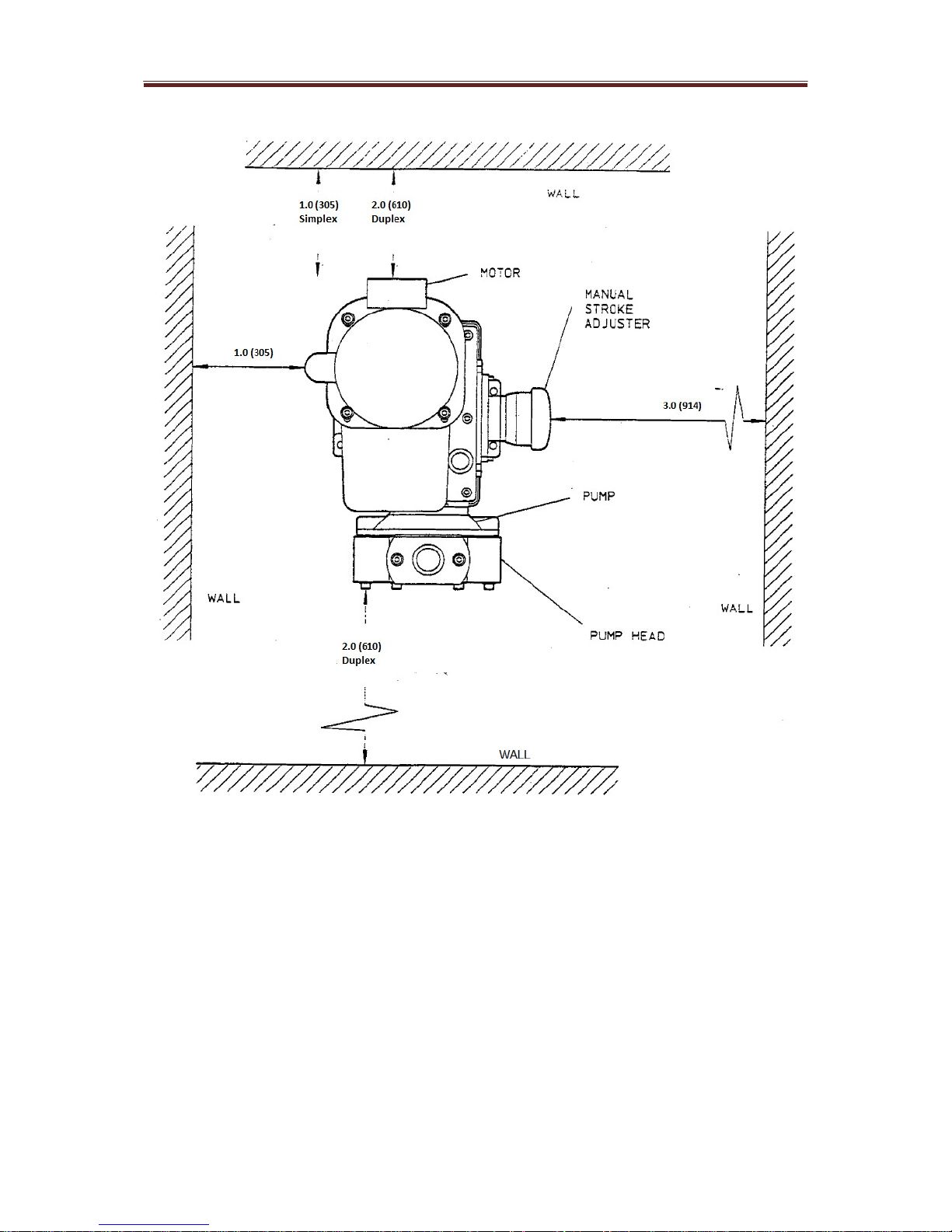
Recommended minimum height from floor to valve connections should be 12 inches (305 mm)
Dimensions are feet and inches (indicates mm)
Simplex and Duplex manual arrangement space recommendations
Drawing 440.400.1-Plunger
 Loading...