

Water Powered Technologies Papa Pump Owner's Manual

a great UK
design
patented design
Owner’s Manual
Installation, Operation and Maintenance Guide
patented desig

Index
3
4
5
6
7
11
14
15
17
18
19
21
24
25
29
33
page no.
description
Kit contents
About the Papa pump
Papa technology
How the Papa pump works
Installation principles
Catchment tank details & installations
Supply tank details and installation
Pump chamber details and installation
Multiple installations
Reference charts
Seradisc filter
Installation & commissioning
Pump parts list
Pump maintenance
Troubleshooting
Specifications
2
Kit Contents
exhaust adaptor
pump
hose assembly
c spanner
Seradisc filters
x 2
spare set valves
2” ball valve
3
pressure vessel
exhaust adaptor
About the Papa pump
Water Source
a typical schematic layout for a Papa Pump system
B
A
C
A: Catchment Tank
B: Supply Tank
C: Pump Chamber
D: Water Storage
D
Flow
Water powered pumping traditionally goes back 1000’s of years where it was
used primarily for low head irrigation. More recently, from the late 1700’s
hydraulic ram pumps were developed as an efficient and effective means of
transporting water over long distances and great heights where they have been
utilised to provide water in most parts of the world prior to the advent of
‘previously inexpensive’ mains water and electricity supplies.
Developed within the UK in the mid-90s, the Papa Pump represents a modern,
smaller, lighter and more effective alternative and is used in many countries to
provide water for a wide variety of uses. With the addition of the revolutionary
composite version, Papa continues to ensure that your water transport
requirements are cost-effective and delivered in a reliable and sustainable
system.
Simple water power
By utilising a naturally flowing water source, the Papa pump is able to transport
up to 30% of that water to the desired location, allowing the residual water to be
returned to the natural source. With minimal maintenance and zero fuel costs
and emissions, the Papa Pump will provide you with a clean and efficient system
for your water transportation requirements including agriculture, horticulture,
irrigation, domestic and industrial use.
4

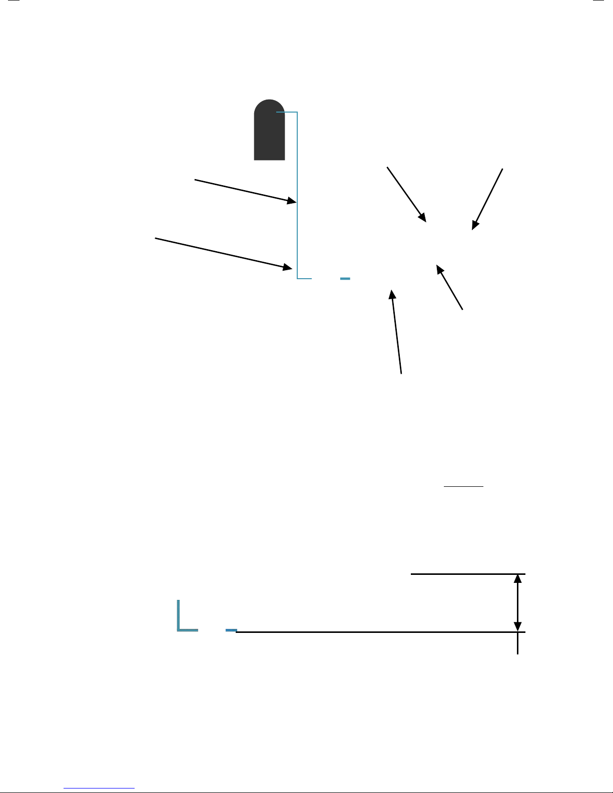
Papa technology
exhaust
port
delivery
port
supply
port
main valve
non-return
valve
5
adjuster
How the Papa pump works
Water enters pump via supply port and flows around main valve to exhaust port.
As the flow increases around the main valve a differential pressure occurs
causing the valve to suddenly close. The flow and mass of water is then directed
through the non-return valve and into the delivery port at a higher pulsed
pressure. This pressure suddenly reduces causing the main valve to reopen and
the cycle repeats.
Turning the adjuster to open the valve allows flow through the pump to be
regulated so that a greater flow generates a greater pressure and water delivery.
6

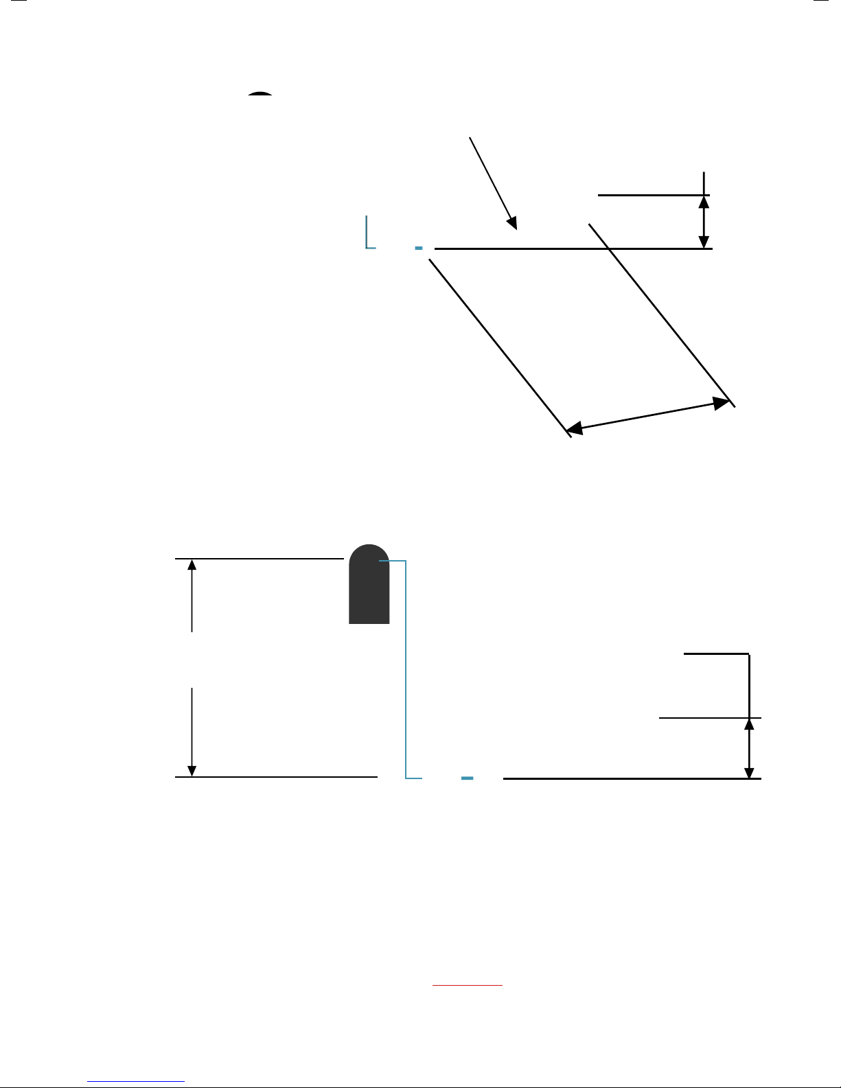
Installation principles
A natural water source is required
river
stream
spring
pond/lake
7
catchment
tank
supply
tank
pump
chamber
water source flow
Plan Elevation
Side Elevation
MORE SUPPLY HEAD = MORE WATER!
Supply
Head
Delivery
Head
catchment
tank
pump
chamber
supply
tank
storage tank
SH
DH
The greater the supply head, the more efficient
the pump is!
8
Supply Head greater
than 2 metres
SH
Site Layout Overview
MORE SUPPLY HEAD = MORE WATER!
A minimum Supply Head of 2 metres is required, but please
ensure that the maximum head is achieved for best results
9
delivery pipe
storage tank
catchment
tank
pump
chamber
supply
tank
feed pipe feed pipe
overflow
pipe
supply
pipe
NOTE! Check that the Delivery Head (DH) does not exceed the pressure rating of
pipes!
The maximum Delivery Head (DH) is 30 x the Supply Head (SH)
Delivery Head DH
= max 30 x SH
Supply Head
SH
10
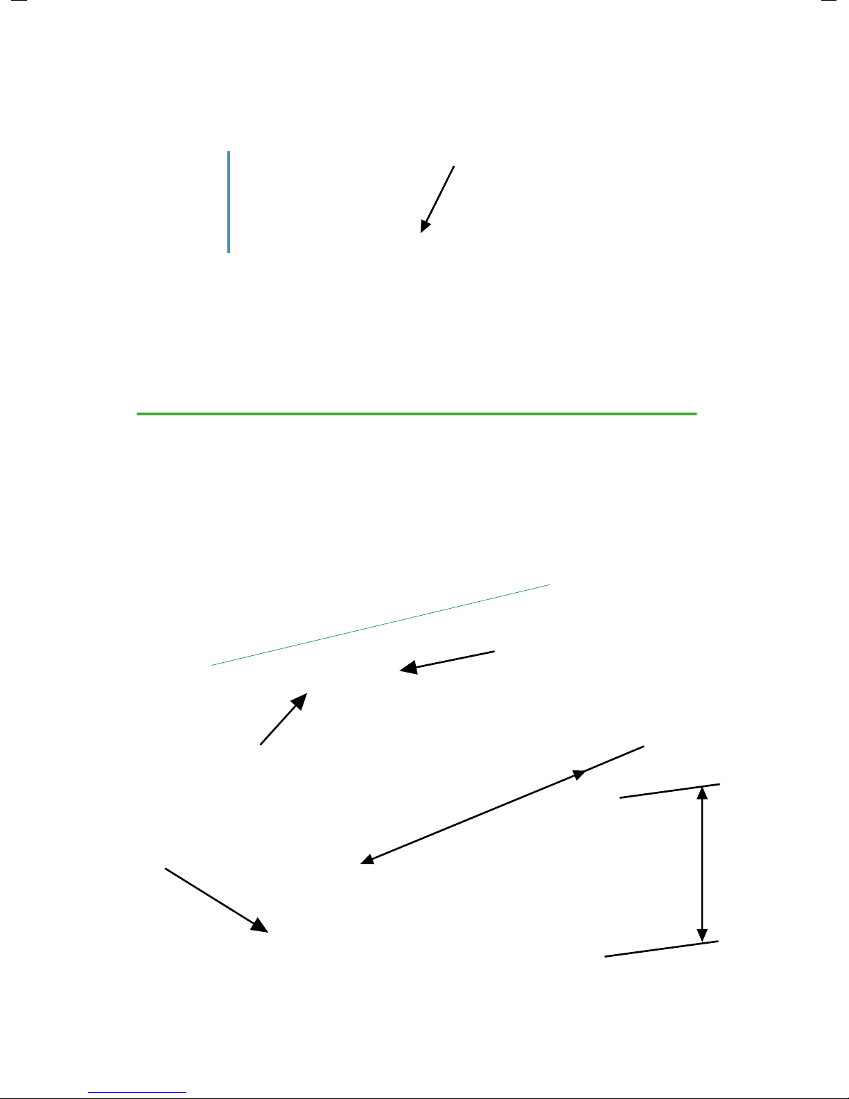
Supply Head
SH
L
Supply Pipe lengt
h
NOTE! The PAPA pump can operate outside of these
parameters but the performance will be affected
Supply Pipe
length
L = 4-7 x SH
Supply Pipe
The Supply Pipe length (L) should be between 4-7 x the Supply Head (SH) for
optimum efficiency and pressure
catchment
tank
feed pipe
supply
tank
Feed Pipe should be straight with a low gradient (1:500) into the Supply Tank, but
check pipe friction chart to establish the most suitable size and gradient.
Catchment Tank details & installations
Catchment method 1
feed pipe
water flow
90 deg bend facing
downstream
1 metre
min
1 metre
min
11
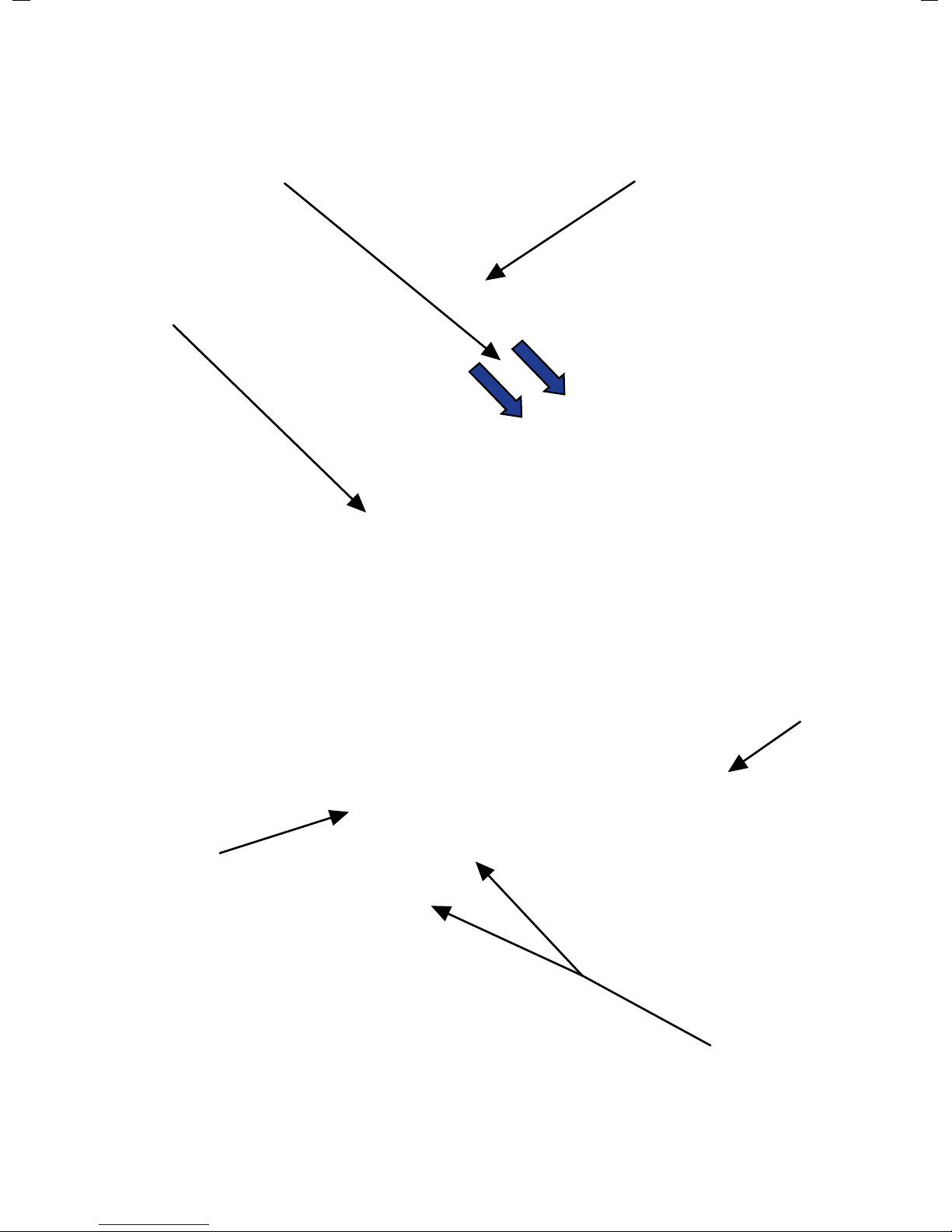
Catchment method 2
feed
pipe
water ingress through
holes drilled in tank
stones used as
coarse filter
feed pipe
inlet from
water source
Seradisc filters
Catchment tank
NOTE! The more Seradisc filters fitted, the better the reliability of the system
12
 Loading...