

Waterous PB13-2515B, PB13-2515, PB13-2525, PB13-2525C, PB13-3025 Operation, Maintenance And Overhaul Instructions
...Page 1
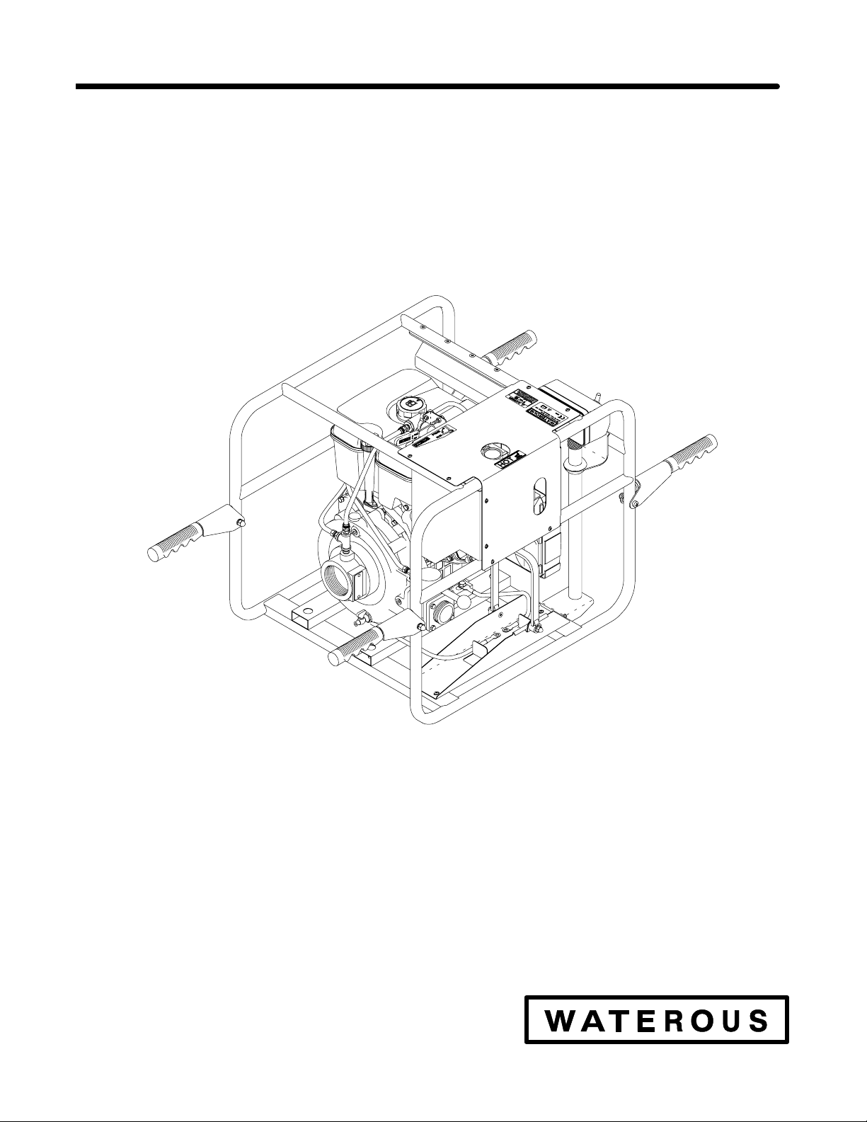
PB13 Series Portable Pump
OPERATION, MAINTENANCE
AND
OVERHAUL INSTRUCTIONS
IL1946
WATEROUS COMPANY
SOUTH ST. PAUL, MINNESOTA 55075 U.S.A.
MODELS:
PB13-2515
PB13-2515B
PB13-2515F
PB13-2525
PB13-2525C
PB13-3025
PB13-3025C
PB13-G2015B
PB13-G2015F
Page 2

Page 3
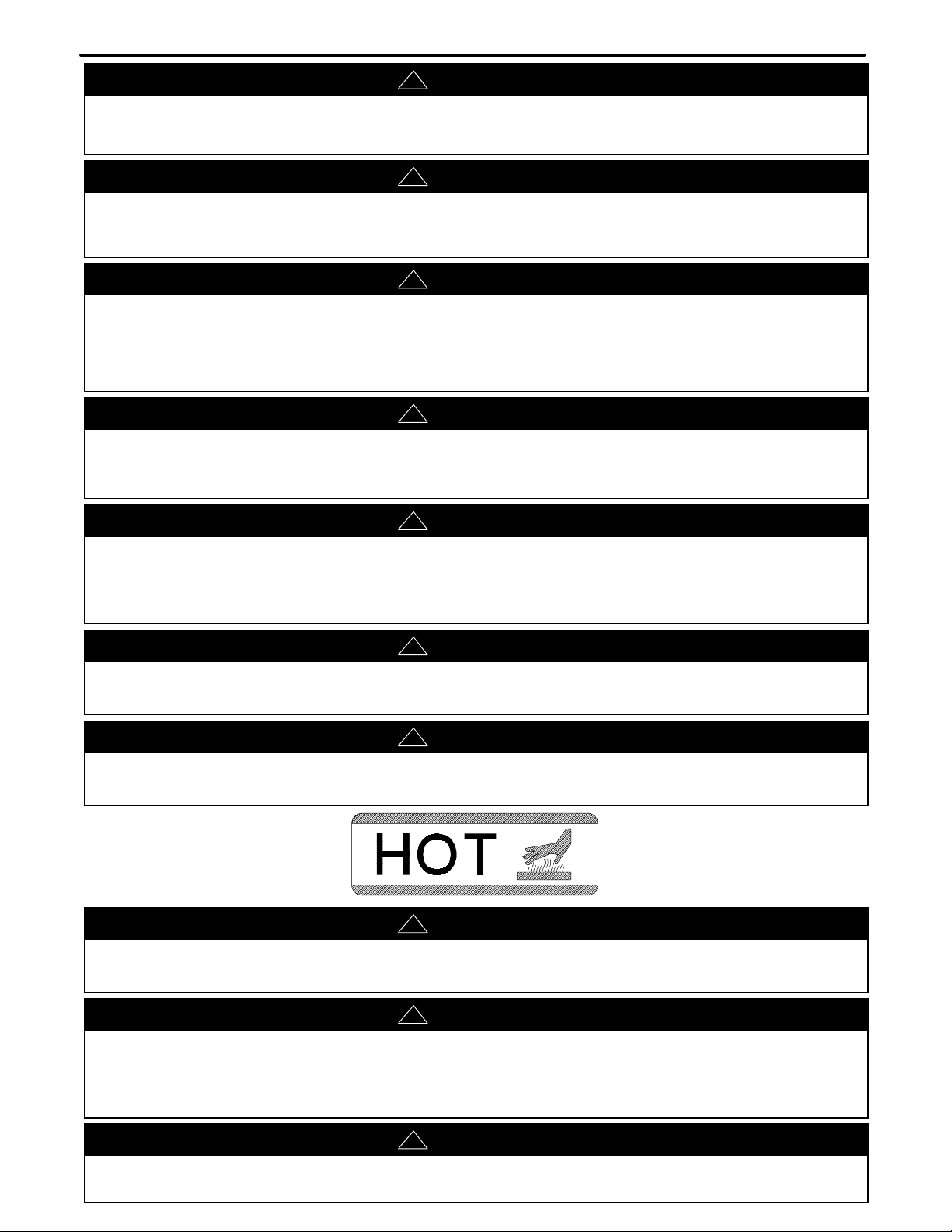
SAFETY INSTRUCTIONS
WARNING
!
Death or serious personal injury might occur if proper operating procedures are not followed. The pump operator, as well as
individuals connecting supply or discharge hoses to the apparatus must be familiar with these pump operating instructions as
well as other operating instructions and manuals for the apparatus, water hydraulics and component limitation.
WARNING
!
Pressure Hazard. May result in personal injury.
Prior to connection or removal of hoses, caps or other closures with pump intake or pump discharge connections, relieve
pressure by opening drains.
WARNING
!
Scalding Water Hazard. May result in serious burns.
When operating the pump, be sure to open at least one discharge valve slightly to prevent the pump from overheating. If
the pump runs for a few minutes completely closed, it may heat the water enough to scald someone when the valve is
opened. Overheating can damage the packing, seals and other pump parts. If the apparatus builder has installed a
by-pass system or other provision designed to prevent overheating, opening a discharge valve may be unnecessary.
WARNING
!
Accidental starting hazard. May cause personal injury to the hand, arm or feet.
Prevent accidental starting by removing the spark plug wire and grounding it when servicing the engine or equipment.
Disconnect negative wire from the battery terminal if equipped with electric starting system.
WARNING
!
Excessive speed notice. May cause personal injury.
Operating an engine at excessive high speeds increases the danger of personal injury. Do not tamper with the governor springs,
governor links or other parts which may cause an increase in governed engine speed. Do not tamper with the engine speed
selected by the original equipment manufacturer.
WARNING
!
Moving or rotating parts hazard. May cause personal injury.
Always keep hands and feet clear of moving or rotating parts to prevent injury.
WARNING
!
High temperature components. May cause severe burns.
Do not touch hot mufflers, cylinders or fins as contact may cause burns.
WARNING
!
Kickback notice. May cause injury to hand or arm.
To prevent hand or arm injury, pull the cord slowly until resistance is felt then pull the starter cord rapidly to avoid kickback.
CAUTION
!
Spark arrestor notice.
This engine is equipped with a spark arrestor for use on forest covered, brush covered or grass covered unimproved land, it
must be maintained in effective working order by the operator. In the state of California, the above is required by law (Section
4442 of the California Public Resources Code.) Other state may have similar laws.
WARNING
!
DO NOT strike the flywheel with a hammer or hard object as this may cause the flywheel to shatter in operation. Use correct
tools to service the engine.
Page 4
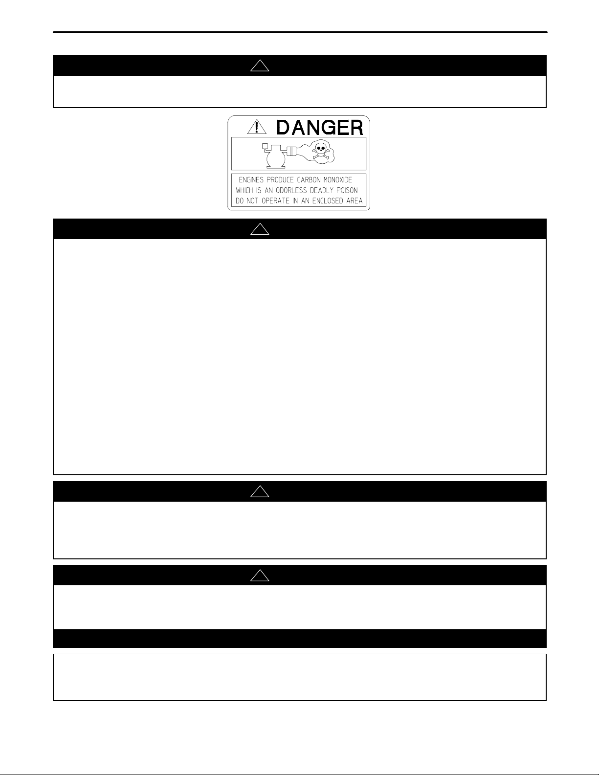
SAFETY INSTRUCTIONS
The PB13 Series Portable Pump is designed and intended for use as portable firefighting equipment.
DANGER
!
Exhaust gas hazard. Can cause illness or death.
Do not run the engine in an enclosed area. Exhaust gases contain carbon monoxide, an odorless, deadly poison.
DANGER
!
Fire or explosion hazard. Can cause personal injury or death.
A fire or explosion may result if the following instructions are not followed:
1. DO NOT remove fuel tank cap nor fill fuel tank while engine is hot or running. (Allow engine to cool two minutes before
refueling.)
2. If gasoline is spilled, move machine away from the area of the spill and avoid creating any source of ignition until the
gasoline has evaporated.
3. DO NOT STORE, SPILL OR USE GASOLINE NEAR AN OPEN FLAME, or devices such as a stove, furnace or water
heater which utilize a pilot light, or devices which can create a spark.
4. Refuel outdoors or only in well ventilated areas.
5. DO NOT OPERATE ENGINE WITHOUT A MUFFLER. Inspect muffler periodically and replace, if necessary.
6. DO NOT use this unit on forest covered, brush covered or grass covered unimproved land unless the spark arrester is
attached to the muffler.
7. DO NOT operate the engine with an accumulation of grass, leaves or other combustible material under, around or behind
the muffler.
8. DO NOT operate the engine if air cleaner or cover directly over the carburetor air intake is removed.
9. DO NOT choke carburetor to stop the engine.
10. DO NOT check for spark with spark plug removed (use an approved tester).
11. DO NOT crank engine with spark plug removed. (If the engine floods, place throttle in “FAST” and crank until engine starts.)
12. DO NOT use the pump to pump flammable liquids.
WARNING
!
Suction and high pressure hazard.
May cause injuries to the hands, fingers or severe cuts or abrasions to the skin.
Never insert hands or fingers into the intake or discharge openings while engine is running. Never spray high pressure water
at a person or animal.
WARNING
!
Equipment Tipping Hazard. May cause personal injury or equipment damage.
DO NOT run the engine if the equipment is not stable and tipping can occur. Mount equipment to a stable base. If pump is hand
carried, place the pump on a firm, level surface to operate. Maximum operating slope is 15_.
WARNING
Pump overheat hazard.
May cause damage to the pump.
Do not run the pump dry for any extended period of time to prevent the pump from overheating.
IMPORTANT NOTES:
1. Ambient operating temperature range: -18_F to 118_F (-28_C to 48_C)
2. Maximum sound pressure level: 95 dBa @ 1.5 meters
3. The PB13 Series Portable Pumps are designed to be carried by two or more people.
Page 5
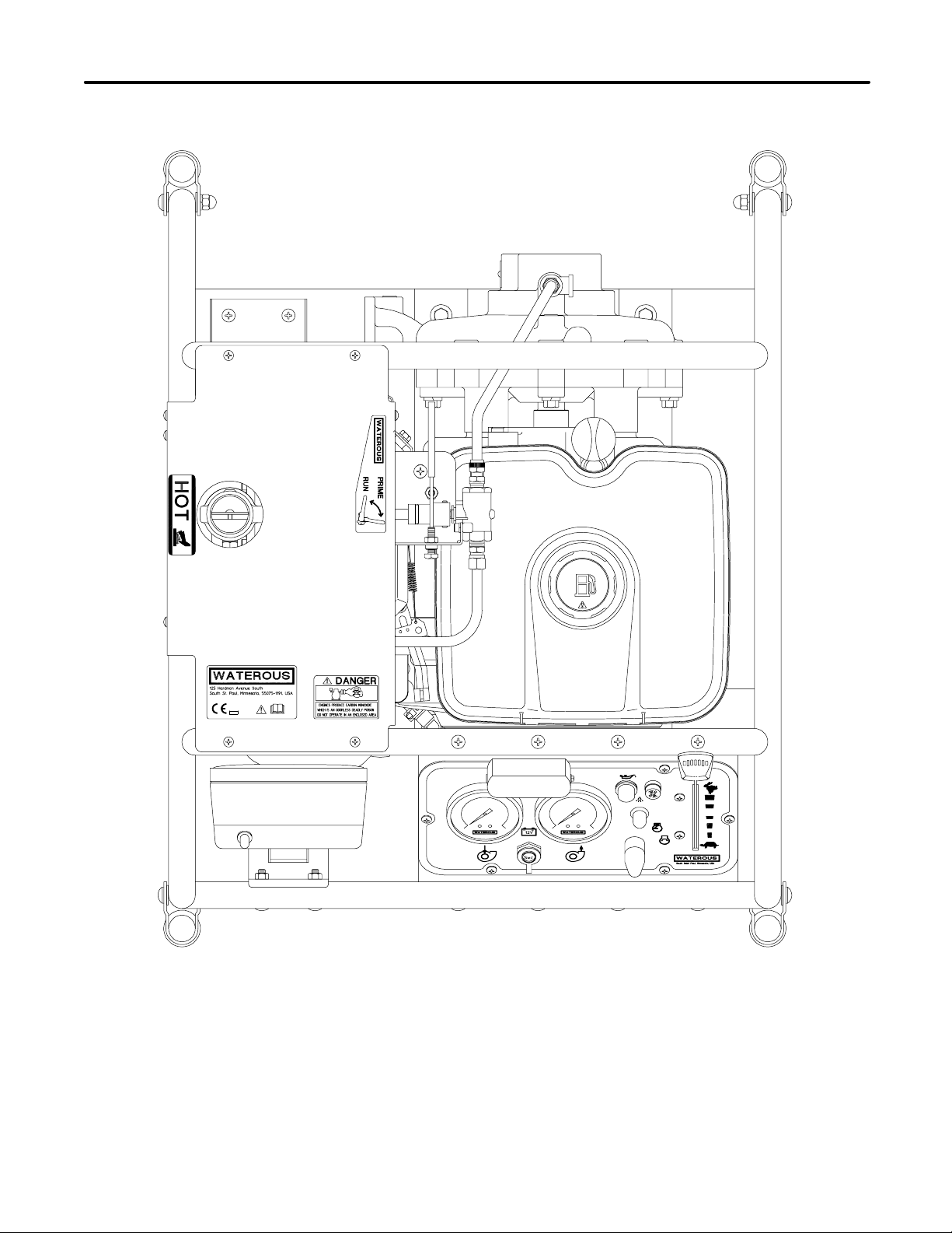
WARNING LABELS
IL2030
Page 6
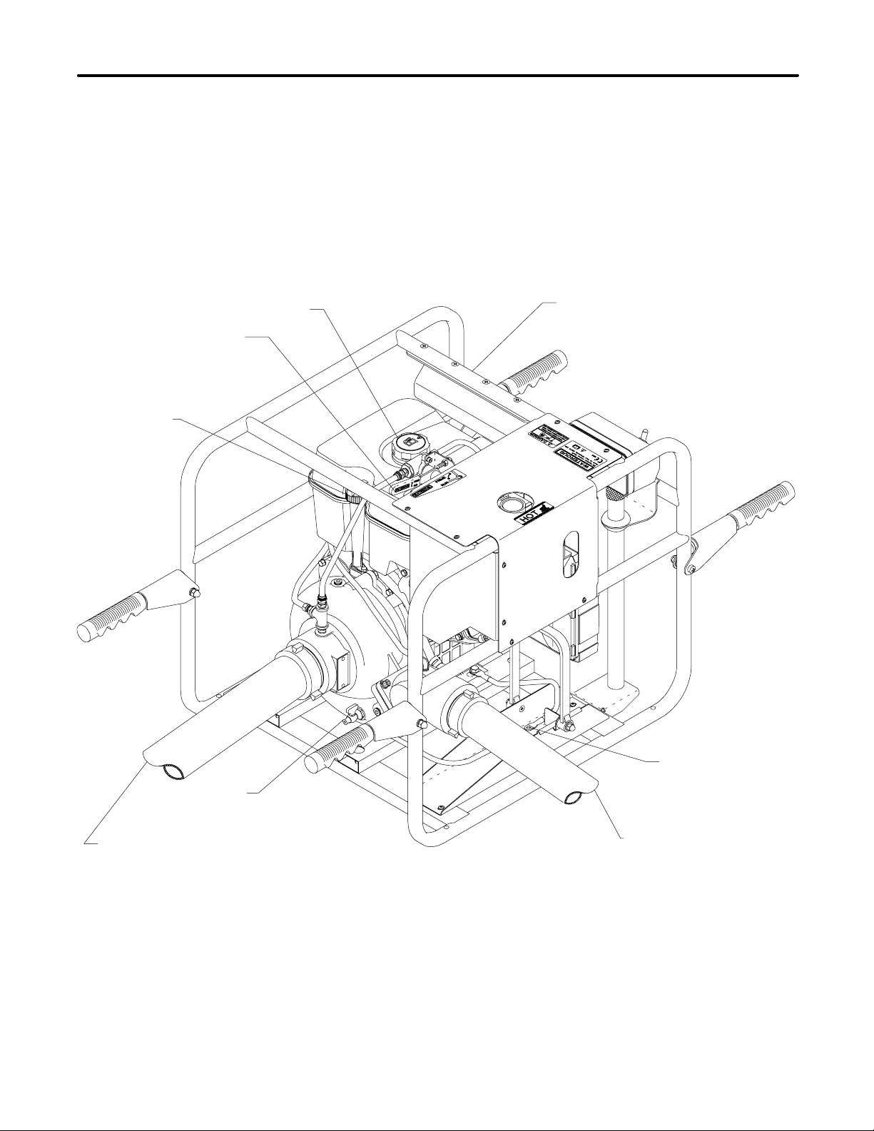
PREPARATION BEFORE OPERATION
Figure 1. Preparation Before Operation
Page 1 of 13
Priming Lever
Oil Fill
Fuel Fill
Operator Panel
Close Pump Drain
Connect Intake Hose
Battery Tray
Connect Discharge Hose
IL2031
Page 7
Page 2 of 13
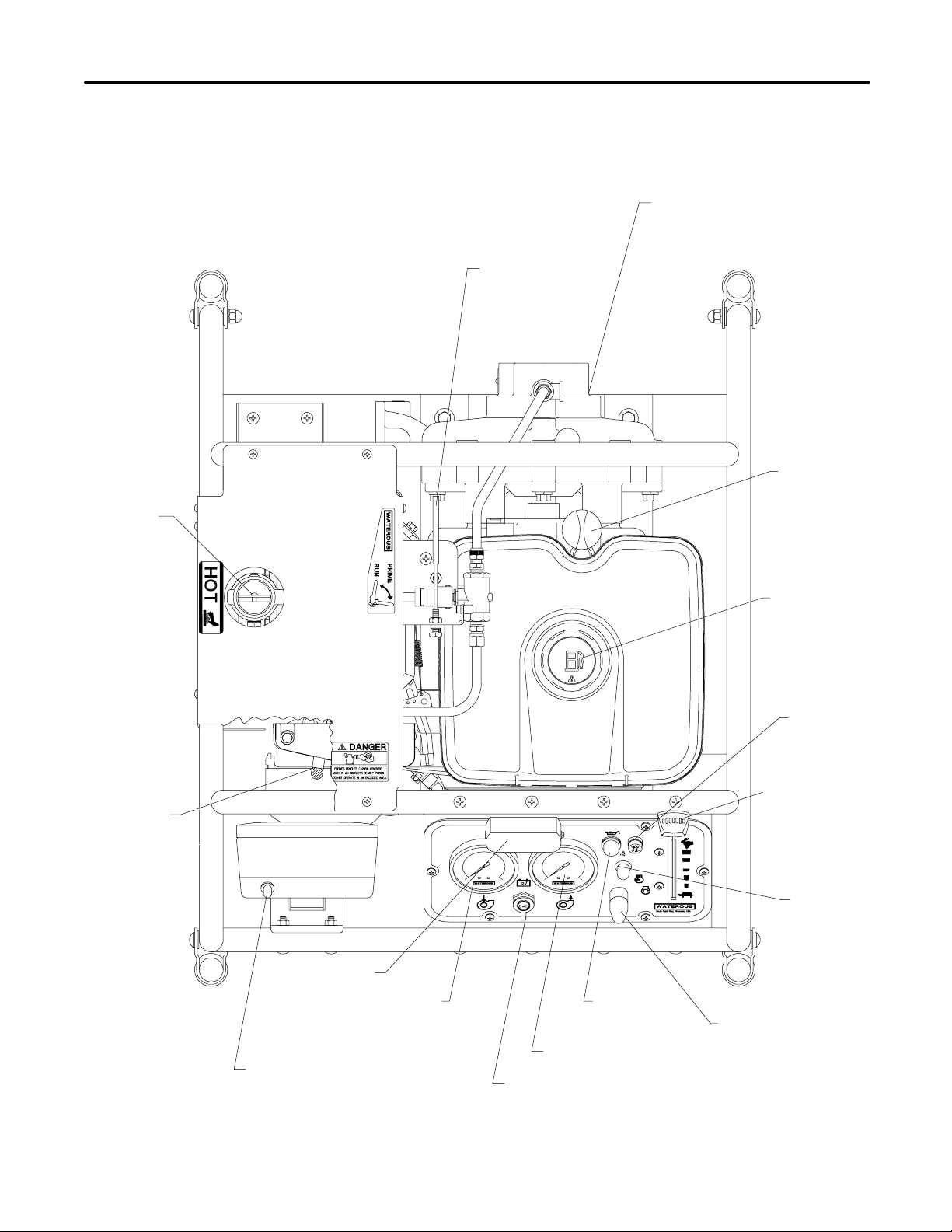
Figure 2. Operation Controls
OPERATION CONTROLS
Pump Drain
(Located at bottom of volute)
Priming Lever
Oil Fill
Engine
Exhaust
Choke
Control
Fuel Fill
Fuse
Engine Speed
Control
(Throttle)
Panel
Light
Switch
Panel Light
Intake Pressure
Mast Light Switch
Low Oil
Level Indicator
Discharge Pressure
12 VDC (Mast Light Connection)
(OFF-RUN-ST OP)
Ignition Switch
IL2032
Page 8
OPERATION AND MAINTENANCE
Page 3 of 13
Preparation Before Operation (See Figure 1)
Symbols
This safety alert symbol indicates that this
message involves personal safety. Words
danger, warning and caution indicated de‐
gree of hazard. Death, personal injury and/‐
or property damage may occur unless in‐
structions are followed carefully.
You are not ready to operate this engine if
you have not read and understood the fol‐
lowing safety items. Read this entire owner/‐
operator manual and the operating instruc‐
tions of the equipment this engine powers.
You are not ready to operate this engine if
you have not read and understood the fol‐
lowing safety items. Read this entire owner/‐
operator manual and the operating instruc‐
tions of the equipment this engine powers.
NOTE: Engines and transmissions are shipped with oil.
Check oil level before operating.
1. Inspect the unit carefully for damage resulting from ship‐
ment. Abusive handling during shipment resulting in ob‐
vious damage to the engine or the pump may cause rub‐
bing of moving parts resulting in severe engine or pump
damage if operation is attempted.
2. Check the unit for bolts or other fasteners which may
have vibrated loose during shipment.
3. These units are equipped to use a type 12N14-3A ``mo‐
torcycle” battery.
Battery Specifications:
• Capacity - 14 Amp Hour
• Approximately 130 cold cranking amps
• Size: 3-1/2 x 5-1/4 x 6-1/2 tall
4. Prepare the engine for starting by reading completely
and following the Briggs and Stratton Operation and
Maintenance Instructions.
5. Fill engine with oil per Briggs & Stratton instructions. The
PB13 Series Portable Pumps use Briggs & Stratton
Model Series 245400 engines.
6. Fill fuel tank. Use clean, fresh, lead-free gasoline with
a minimum of 85 octane. (See Briggs & Stratton instruc‐
tions for more detail.) The engine should be refueled
prior to use to avoid the need to refuel when it is hot.
7. Fill transmission with 1 pint of SAE 90W oil through top
plug or breather elbow. Remove oil level plug to check
oil level (gear driven pump only).
8. With the ignition switch OFF, rotate the engine crank‐
shaft several times with the rewind start rope to make
sure the engine and pump turn over freely with no abnor‐
mal rubbing noises.
WARNING
!
Low oil. May result in engine power loss, personal
injury or property damage.
Maintain correct oil level. Check oil level each time en‐
gine is refueled. Low oil level may cause loss of engine
power and may result in personal injury or property dam‐
age.
Connections between the pump and intake and discharge
hoses or piping should be made leakproof. Wrench torque
should be limited to 80 ft. lb. maximum when making con‐
nections. If more than 80 ft. lb. torque is required, use two
wrenches, one wrench on the pump intake or discharge fit‐
ting and one wrench on the hose or pipe being attached. Bal‐
ancing the torque applied between the two wrenches will
avoid excessive forces to the pumping unit.
When pumping units are permanently mounted in an appa‐
ratus and attached to rigid piping, connections between the
pump and the piping should be made using flexible cou‐
plings to avoid applying excessive forces to the pump.
Starting the Engine (See Figure 2)
1. Refer to the Briggs & Stratton Operation & Maintenance
Instructions.
2. Move the choke control lever to the “CHOKE” position.
3. Move the throttle control to the “FAST” position.
4. Rotate ignition switch to the “RUN” position.
5. Rotate and hold the ignition switch in the “START” posi‐
tion to operate the starter motor relay and start engine.
(Alternate: Use manual rope start.)
6. After the engine starts, return the ignition switch to the
“RUN” psotion, return the choke control to the “RUN”
position and adjust the throttle as required.
Priming the Pump
The PB13 Series utilize an exhaust primer.
1. Connect intake and discharge hoses or piping.
2. Close the discharge valve if so equipped.
3. Start engine and advance the throttle to “FAST” position.
4. Pull the priming lever located at the top of the engine to
“PRIME” position.
Alternate: Pull the primer lever and advance the
throttle.
5. Operate primer until water is ejected from it.
Page 9

Page 4 of 13
OPERATION AND MAINTENANCE
NOTE: For high lift applications (10 foot or higher) when
the pump is new, priming operation may be improved if
the engine choke is engauged slightly (no more than 1/4
of choke lever travel) after advancing the throttle to full
open. Once the pump is primed, return choke to the
“RUN” position.
6. Return the priming lever to the “RUN” position.
7. Open the discharge valve if so equipped.
When a PB13 pump is used from draft in below freezing
weather, the following shut-down procedure should be
used:
1. When pumping is completed and discharge hose dis‐
connected, move the priming lever to the “PRIME” posi‐
tion to drain the intake and the priming line back into the
water supply.
2. Disconnect the intake hose. Start the engine and oper‐
ate the primer until no more water comes out.
3. Stop the engine and open the volute drain.
Operating the Pump
The pump performance can be varied by:
1. Controlling a discharge valve or nozzle. Opening the
valve increases flow and decreases discharge pres‐
sure.
2. Controlling engine speed via the throttle control. In‐
creasing the engine speed increases the discharge
pressure and flow.
WARNING
!
Pump Overheating.
May cause personal injury or pump damage.
When operating the pump, be sure to open the discharge
valve slightly to prevent the pump from overheating. If the
pump runs even for a few minutes completely closed it
may heat the water enough to scald someone when the
valve is opened. Overheating can damage the seals and
other pump parts.
Pumping from Water Tank
1. Open valves in piping between water tank and pump in‐
take, and the discharge valve.
2. Allow about 30 seconds for water to flow into pump.
NOTE: Priming the pump may be necessary under
some conditions because of the air trapped in pump
and piping.
3. Adjust engine speed and discharge nozzle or valve to
obtain desired discharge pressure and flow.
CAUTION
Do not attempt to pump more water than is avail‐
able from water tank. Always make sure the in‐
take pressure gauge reading stays above zero.
After Pumping
1. Stop engine.
2. If pumping anything but clean water, open all valves and
open all drains. Flush entire system with clean, fresh wa‐
ter for several minutes to remove all traces of impurities.
3. Close all drains and install intake and discharge caps.
4. Operate primer lever to drain any fluid from the priming
pump.
Pumping from Hydrant or Relay
1. Start Engine.
2. Open intake, hydrant and other valves as necessary to
allow water to enter the pump.
CAUTION
Pump has a mechanical seal, limit intake pres‐
sure to 75 psi if possible. Although the pump will
operate properly with higher intake pressure,
such operation will greatly accelerate mechani‐
cal seal wear.
CAUTION
Freezing water hazard.
May cause damage to the pump.
If the pump is exposed to freezing temperatures, drain all
water from pump, lines and accessories.
WARNING
!
Pressure Hazard.
May cause personal injury.
When the pump stops there is no stored pressure but
there could be pressure in the hoses. Use care when
disconnecting hoses and allow any residual pressure to
bleed off before uncoupling.
3. Open the discharge valve and increase engine speed to
obtain desired discharge pressure and capacity.
CAUTION
Do not attempt to pump more water than is avail‐
able from the hydrant or relaying pumper. Make
sure the intake pressure gauge reading stays
above zero. Some fire departments operate at
a minimum intake pressure of 10 psi when
pumping from hydrant or in relay to prevent a
“soft” intake hose from collapsing.
After Pumping (See “Pumping from Tank” above)
Page 10

OPERATION AND MAINTENANCE
Page 5 of 13
Pumping from Draft
NOTE: To get full capacity, quick prime and maintain
pump efficiency:
a.) Position truck as near as possible to water supply.
b.) Avoid humps or sharp bends in intake hose. Make sure
no part of hose is higher than pump intake inlet. (Air
pockets in intake hose may cause loss of prime or erratic
pump action and may reduce pump capacity.)
c.) Make sure all intake connections are tight and discharge
valves are closed.
d.) Immerse intake strainer at least two feet below water
surface to prevent pump from drawing air.(Whirlpools
forming above intake strainer indicate that strainer is too
close to surface of water.)
e.) Make sure intake strainer is far enough from bottom to
prevent pumping sand, gravel or other foreign matter.
1. Prime the pump (see separate).
2. Open discharge valves and increase engine speed to
obtain desired discharge pressure and capacity.
After Pumping (See “Pumping from Tank” above)
Engine Maintenance
Refer to Briggs and Stratton Operation and Maintenance In‐
structions.
Pump Maintenance
The pump requires no maintenance other than draining the
volute body after each use. If the pump has been handling
chemicals, salt water or dirty water, flush entire system with
clean, fresh water for several minutes to remove all traces of
impurities.
Transmission Maintenance
(PB13G Gear Case Models Only)
Drain and refill with one pint SAE 90 weight gear oil after 100
hours of operation or one year.
Spark Arresting Muffler
Every 100 hours, examine the spark arrestor located inside
the exhaust primer adapter. Clean screen or replace if dam‐
aged. Removal of the spark arrestor will require removal of
the butterfly assembly from the primer adapter.
ENGINE AND PUMP REPAIR
Repairs to be done during the Waterous or Briggs and Strat‐
ton warranty period must be done in accordance with the ap‐
propriate warranty policy.
Engine Repair
If engine service or repair is needed, refer to Briggs and
Stratton Operation and Maintenance Instructions. NOTE:
The control panel, primer, spark arrestor and muffler are not
furnished by the engine manufacturer. Refer to Waterous
Company Service Parts List supplied with the pump for
these parts.
Pump Repair
Pump repair should be done by Waterous authorized ser‐
vice personnel. Alternatively, parts can be purchased from
Waterous Company and installed by any mechanic familiar
with pump overhaul and repair practices and procedures.
Service Parts Lists are provided which give part descriptions
and part Reference Numbers for ordering. Be sure to give
pump model and serial number and Parts List number when
ordering parts.
Page 11
Page 6 of 13
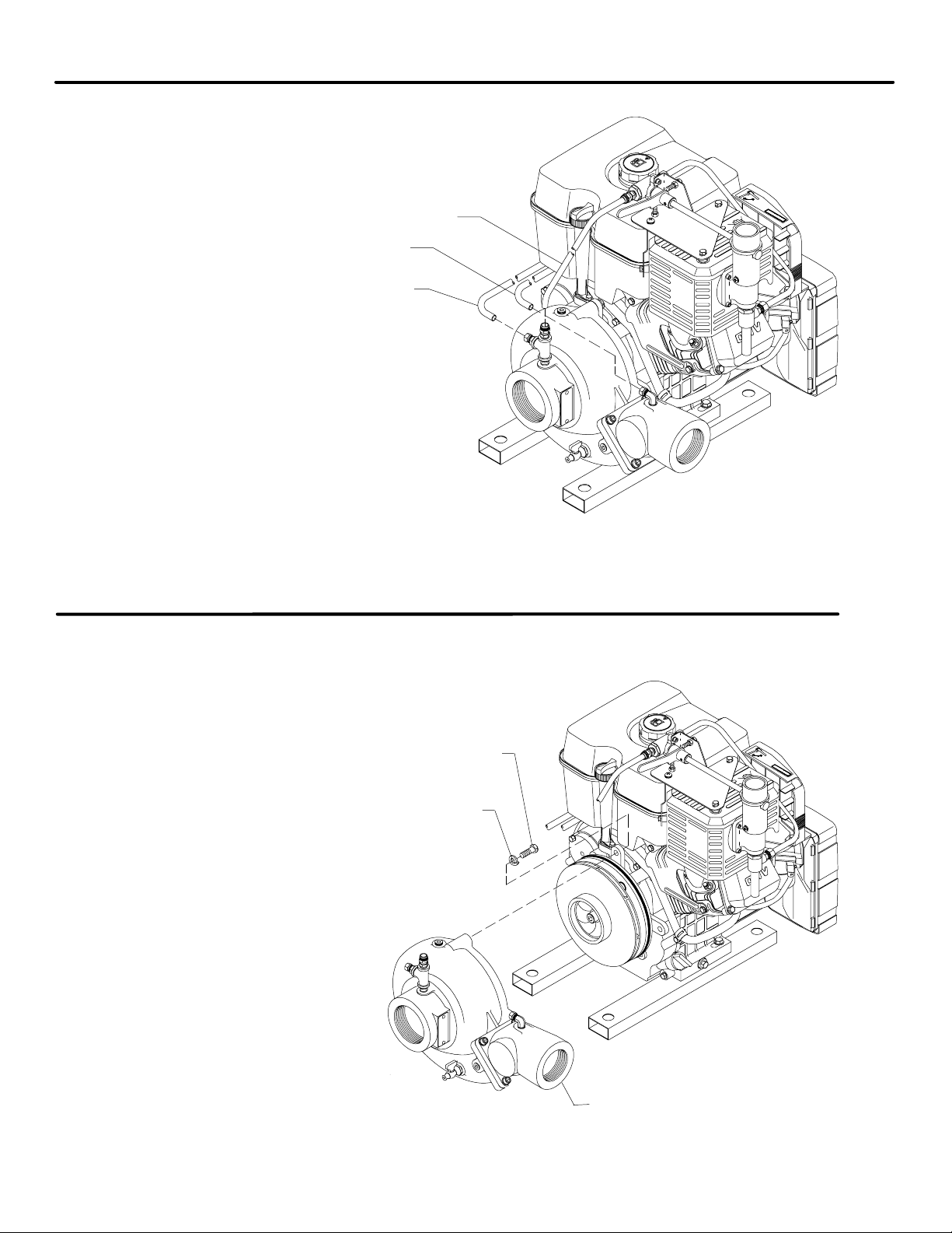
OVERHAUL - DIRECT MOUNTED PUMP
Primer Tube
Discharge Gauge Tube
Intake Gauge Tube
1. Disconnect any intake and discharge piping. It
may not be necessary to remove intake or dis‐
charge adapters, or discharge valve.
2. Disconnect the nylon tubes attached to the volute
body and discharge elbow.
Hex Hd Screw, 3/8-16 x 1 in.
Lock Washer, 3/8 in.
1. Remove (4) cap screws and lock
washers from the engine side of the
pump volute body. Slide the volute
body off the adapter attached to the
engine.
The muffler and control panel assem‐
bly is shown removed for clarity.
2. Remove wear ring from volute body if
necessary.
IL1935
IL1936
Volute Body with Wear Ring
Page 12
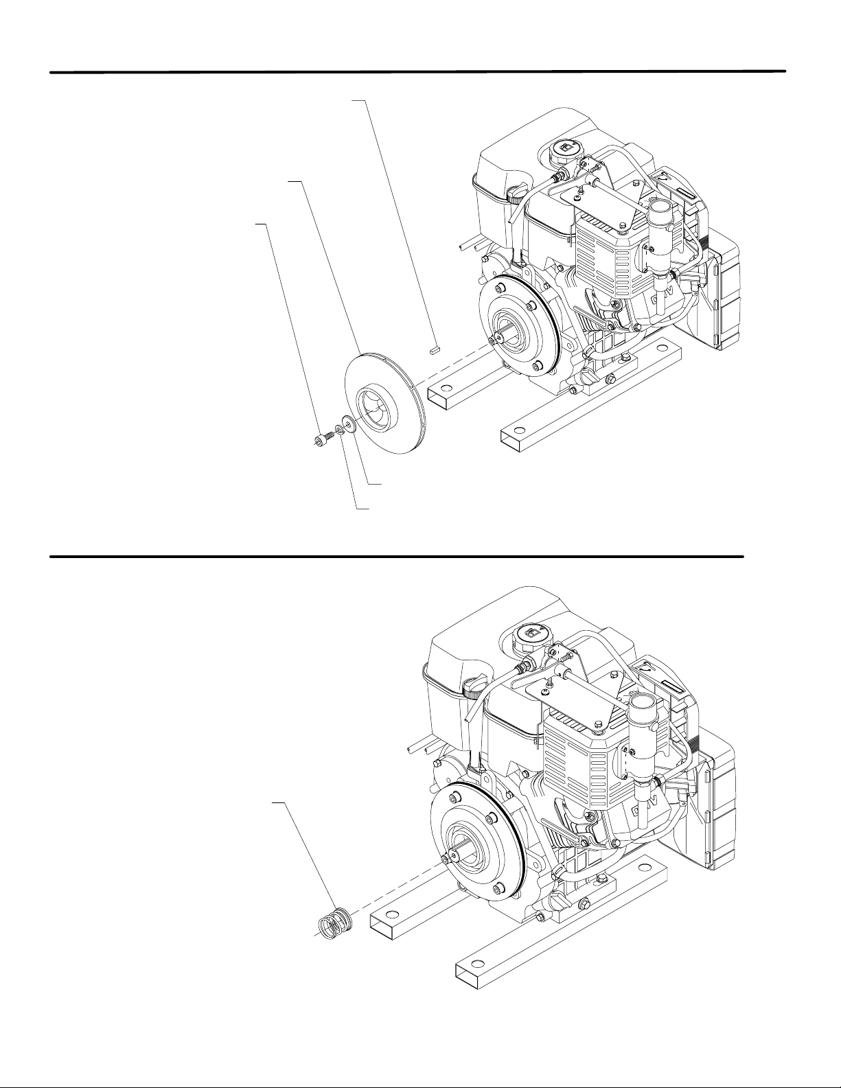
OVERHAUL - DIRECT MOUNTED PUMP
Square Key, 1/4 x 3/4 in. SS
Impeller
Socket Hd Screw,
7/16-20 x 1 in.
1. Remove the socket head cap screw
and lock washer holding the impel‐
ler to the engine crankshaft.
2. If the impeller does not pull off the
shaft easily, 1/4-20 puller holes are
provided in the impeller to assist in
removal. Be sure to protect the
tapped hole in the shaft when using
any type of puller.
3. Remove the square key.
Lock Washer,
7/16 in.
Page 7 of 13
IL1937
Impeller Washer
Mechanical Seal
Remove the mechanical seal rotating parts. The
stationary seal ring will remain in the pump adapter.
IL1938
Page 13
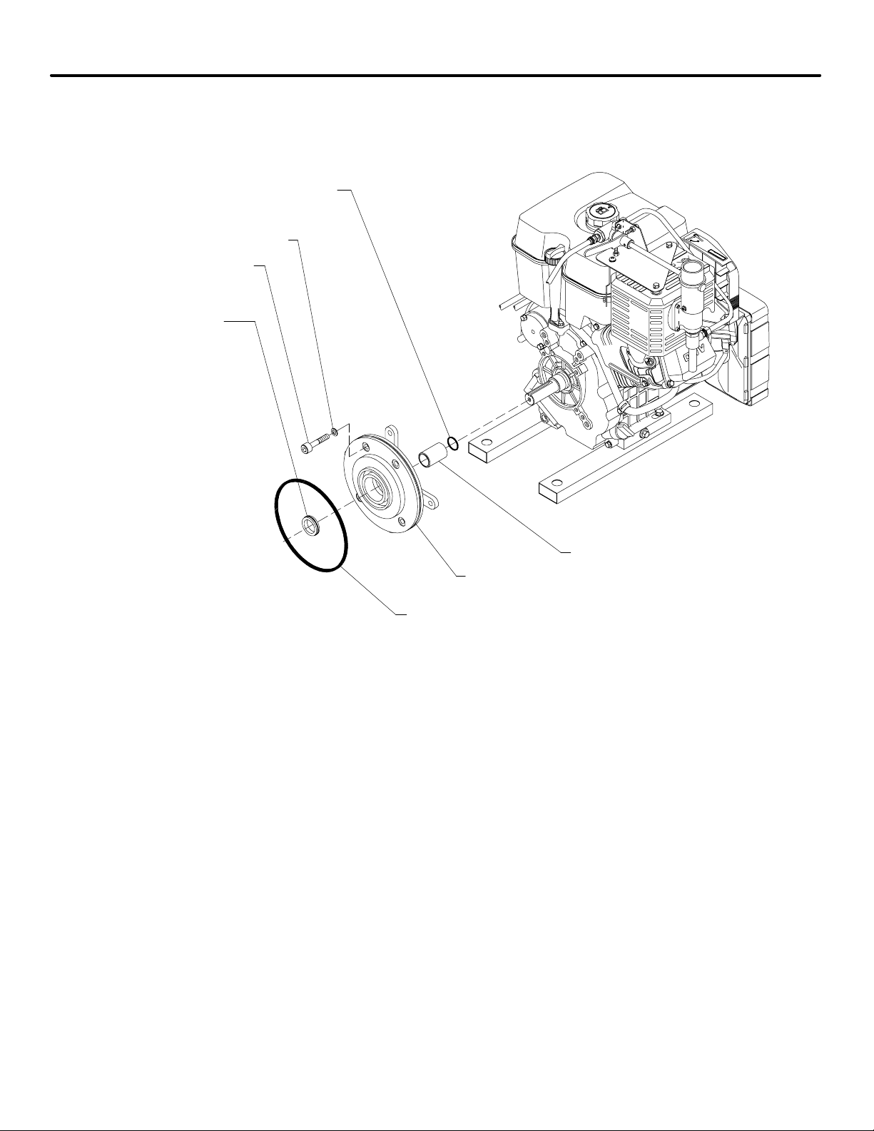
Page 8 of 13
Mechanical Seal
Stationary Seal Ring
OVERHAUL - DIRECT MOUNTED PUMP
O-ring, 1 x 1-1/8 in.
Copper Washer, 3/8 in.
Socket Hd Screw,
3/8-16 x 2-3/4 in.
IL1939
Shaft Sleeve
Pump Adapter with Wear Ring
O-ring, 7-3/4 x 8 in.
1. Remove the (4) socket head cap screws and copper washers holding the pump adapter to the engine.
2. Remove the pump adapter.
3. Press out the mechanical seal stationary seal ring.
4. Remove the pump adapter O-ring.
5. Remove wear ring if required.
6. Remove the shaft sleeve and O-ring.
Page 14
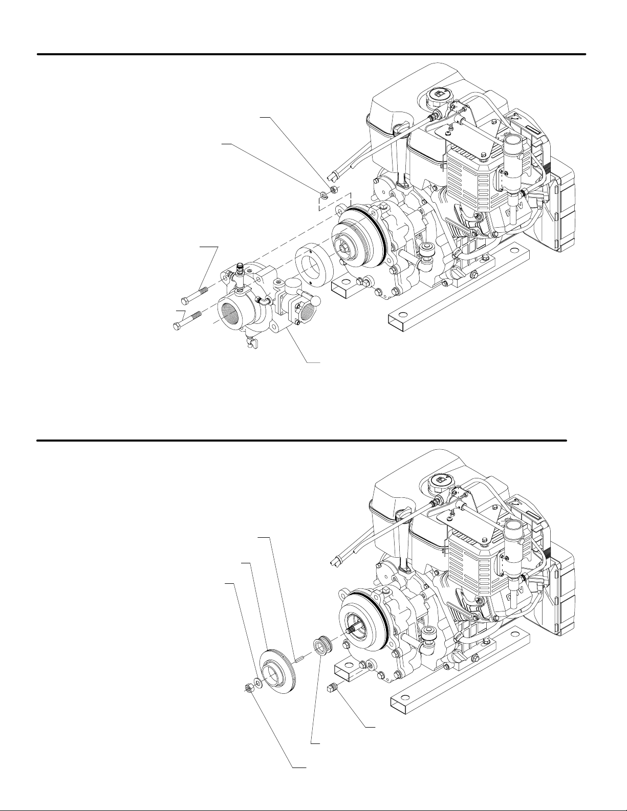
OVERHAUL - GEARED PUMP
Hex Nut, 7/16-20
Lock Washer, 7/16 in.
Hex Hd Screw, 7/16-20 x 2-3/4 in.
Hex Hd Screw, 7/16-20 x 3 in.
Page 9 of 13
IL1940
1. Remove (4) hex head screws the pump volute body. Slide
the volute body off the adapter attached to the engine. Wear
ring will come off with body.
The muffler and control panel are shown removed for clarity.
2. Remove wear ring if required.
Square Key, 3/16 x 1 in., SS
Impeller
Flat Washer, 1/2 in., SS
1. Remove the impeller nut and flat washer
from the impeller shaft. If the impeller
does not pull off the impeller shaft easily,
use a gear puller or two pry bars between
the impeller and adapter. Remove the
square key. The mechanical seal rotat‐
ing parts will come off with the impeller.
The stationary seal ring will remain with
the adapter.
2. Drain oil from gear case by removing the
magnetic plug.
3. Clean the magentic plug.
Pump Volute Body with Wear Ring
IL1941
Magnetic Plug
Mechanical Seal
Self Locking Impeller Nut
Page 15
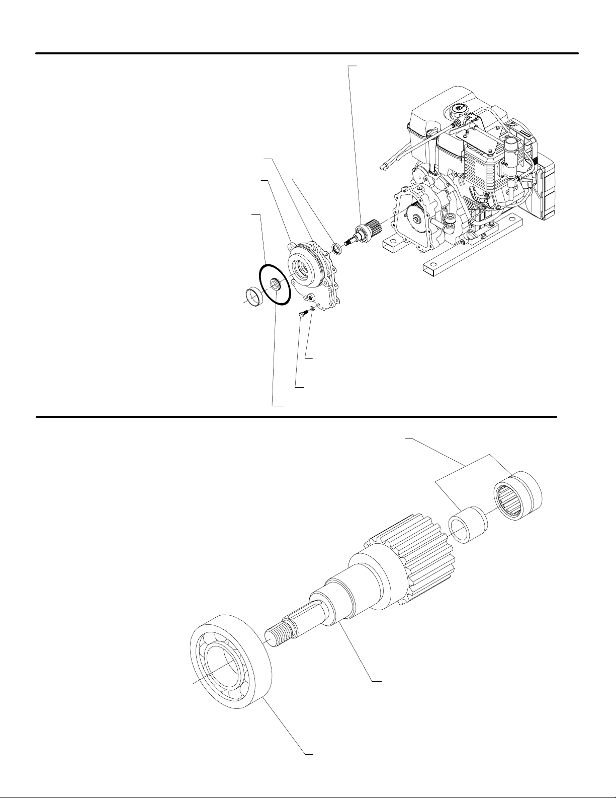
Page 10 of 13
OVERHAUL - GEARED PUMP
Impeller Shaft and Bearing Assembly
Gear Case Gasket
Gear Case Cover with Wear Ring
O-ring, 5-3/4 x 6 in.
1. Remove the 10 hex head screws and
lock washers from the gear case cover.
2. Remove the cover from the gear case.
Press out the impeller shaft and bear‐
ing assembly from the cover.
3. Remove gear case gasket.
4. Press out the mechanical seal station‐
ary seal ring and the oil seal.
5. Remove wear ring if required.
Oil Seal
IL1942
Lock Washer, 3/8 in.
Hex Hd Screw, 3/8-16 x 1 in.
Mechanical Seal Stationary Seal Ring
Needle / Thrust Bearing
1. The impeller shaft / driven gear as‐
sembly with the ball bearing, pinion
gear, spacer, needle bearing inner
race and snap ring should not re‐
quire disassembly unless inspection
reveals wear of the ball bearing,
needle bearing race or pinion gear.
2. Slide the needle bearing inner race
off the end of the impeller shaft.
Impeller Shaft / Driven Gear
IL1943
Ball Bearing
Page 16
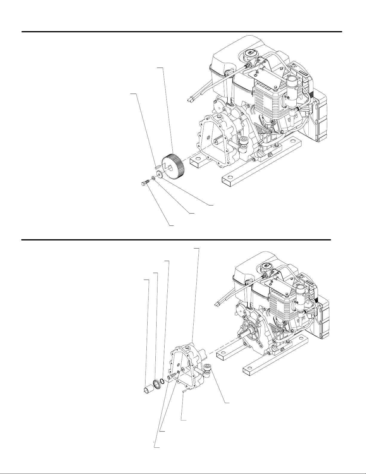
OVERHAUL - GEARED PUMP
Drive Gear
Square Key, 1/4 x 1-1/8 in.
1. Remove the hex head screw and washers
that hold the drive gear to the engine
crankshaft.
2. Pull the drive gear off the shaft.
CAUTION:
Do not damage internal thread of the shaft.
3. Remove the square key.
Page 11 of 13
IL1944
Impeller Washer
Lock Washer, 7/16 in.
O-ring, 1 x 1-1/8 in.
Shaft Sleeve
1. Remove the (4) socket head cap
screws and copper washers holding
the gear case to the engine.
2. Remove the gear case. Press out
the oil seal.
3. If oil has been leaking past the shaft
sleeve, the O-ring seal should be
replaced. Remove the sleeve. Do
not mar the sleeve surface under
the seal.
4. Check to be sure the breather is not
plugged.
Hex Hd Screw, 7/16-20 x 1 in.
Gear Case
Oil Seal
IL1945
Breather
Dowel Pin, 5/16 x 3/4 in.
Copper Washer, 3/8 in.
Socket Head Screw, 3/8-16 x 2-1/4 in.
Page 17

Page 12 of 13
After the pump has been disassembled, check the following before reassembly:
INSPECTION
Impeller Wear
1. Check the wear hubs on the impeller for excessive
wear, or clearance with the wear rings. If the clear‐
ance exceeds 0.020/0.025 in., or if the impeller hubs
are badly scored or grooved, replace the impeller and
both wear rings. Tapped holes are provided in each
wear ring to aid in removing them.
2. Check all O-rings for cuts,nicks, or other damage.
Mechanical Seal
1. When a pump is disassembled, it is advisable to in‐
stall a new mechanical seal during reassembly, espe‐
cially if the pump had been in service for a long period
of time.
2. Check the shaft sleeve in the area under the mechani‐
cal seal bellows to be sure it is free of severe
scratches or other damage. Also check the impeller
hub in the area under the mechanical seal to be sure
it is free from scratches or other damage.
Oil Seals
Check the impeller shaft and engine crankshaft sleeve for
signs of severe wear from the oil seal.
Ball Bearing, Gears and Needle Bearing
Check for severe wear and replace as necessary.
Page 18

REASSEMBLY AND TESTING
Page 13 of 13
Reassembling the pump is basically the reverse of disassemb‐
ly. The following guidelines will help in reassembly.
1. Check the engine crankshaft for any corrosion deposits
that will interfere with seating and sealing of the shaft
sleeve.
2. Lubricate all O-rings when installing.
3. The shaft sleeve should seat down tight against the shoul‐
der of the engine crankshaft. It may ”pop” back slightly on
Direct Mounted Pump
1. Lubricate the crank shaft with light oil. Carefully install O- ‐
ring followed by the shaft sleeve. Be sure there are no burrs
on the end of the sleeve.
2. Install the mechanical seal stationary ring in the pump
adapter, being careful to not scratch the sealing surface.
Clean sealing surface with soft cloth and denatured alco‐
hol.
3. Install new wear ring if required in pump adapter and vo‐
lute body.
4. Mount pump adapter to engine. Replace the copper seal‐
ing washers under the socket head cap screws that se‐
cure the pump adapter to the engine, if they show signs
of being badly bowed, cracked or corroded.
5. Clean crank shaft. Lubricate shaft and inside diameter of
mechanical seal bellows assembly with water based lu‐
bricant. Be sure sealing surface of primary ring is clean.
Geared Pump
initial installation, but will seat down tight when the impel‐
ler or drive gear is tightened onto the shaft.
4. When installing mechanical seal seat ring, be careful not
to scratch the sealing surface that contacts the mechani‐
cal seal primary ring.
5. When installing new wear rings, press them into the bores
carefully so they seat down square at the bottom of the
bore.
Wipe with soft cloth and denatured alcohol before installa‐
tion.
6. Install bellows assembly onto crank shaft with sealing sur‐
face facing the stationary ring. Push bellows assembly
until primary ring contacts stationary ring.
7. Install the impeller key and impeller. Make sure it is seat‐
ing tight against the shaft sleeve by checking for any gap
where the sleeve seats against the engine crankshaft
shoulder. These surfaces should be tight together with no
gap.
8. Press new wear ring (if required) into the volute. Coat out‐
side diameter with never seize product.
9. Place the volute over the lubricated O- ring of the adapter and
replace the 4 bolts, nuts and lock washers.
10. Complete reassembly of the pump and any fittings pre‐
viously removed.
1. Install O- ring and shaft sleeve on engine crank shaft oil
seals into gear case. Lubricate the crank shaft with light oil.
Carefully install O- ring followed by the shaft sleeve. Be sure
there are no burrs on the end of the sleeve.
Before installing an oil seal in a housing, apply a thin
2.
coat of sealant to housing oil seal seat. (Waterous
recommends Loctite Ultra Blue RTV Silicon Sealant to
Permatex Super 300).
gear case are clean. Always install a seal with the seal lip
facing in. Apply force to the outer edge of the seal and
press in evenly.
3. Position the gear case over the shaft sleeve on the engine
and replace the four socket head cap screws and washers.
Inspect and replace washers as necessary.
4. Insert the key, gear, hex head and washers on the engine
crankshaft. Tighten screw securely.
5. Install the mechanical seal stationary ring and oil seal in
the gear case cover adapter, being careful not to scratch
the sealing surfaces. Clean sealing surface with soft cloth
and denatured alcohol.
6. Install new wear ring if required in gear case cover.
Be sure that the seal, shaft and
Testing
1. Before testing the pump, rotate the engine crankshaft with
the engine starter or rope. The spark plug wire should be
disconnected. Be sure there are no abnormal rubbing
noises.
2. The mechanical seal may leak when the pump is first run
after it has been repaired. This leakage should stop after
the seal faces run-in.
7. Insert the impeller shaft assembly in the gear case cover.
8. Using a new gasket, place the gear case cover on the
gear case and replace the ten hex head screws and lock
washers.
9. Clean impeller hub. Lubricate hub and inside diameter of
mechanical seal bellows assembly with water based lu‐
bricant. Install bellows onto impeller hub with primary ring
facing the stationary ring. Push bellows assembly on until
it contacts shoulder on impeller hub. Clean sealing sur‐
face of primary ring with a soft cloth and denatured alco‐
hol.
10. Install the key and then the impeller on the shaft.
11. Install the impeller washer and self locking nut. Coat shaft
threads and nut with Locktite 242 or equivalent. Tighten
nut.
12. Press new wear ring (if required) into the volute.
13. Place the volute over the lubricated O- ring of the adapter and
replace the 4 bolts, nuts and lock washers.
14. Complete reassembly of the pump and any fittings pre‐
viously removed.
3. With the pump running, check for unusual noises or leaks
at volute joints, adapter/gear case engine screws, or shaft
sleeve. These should be corrected before the pump is re‐
turned to service.
Page 19

CONDITIONAL WARRANTY POLICY
WATEROUS warrants, to the original Buyer only, that products and parts manufactured by WATEROUS will be
free from defects in material and workmanship under normal use and service for a period of five (5) years from the
date the product is first placed in service, or five and one-half (5-1/2) years from the date of shipment by Waterous,
whichever period shall be the first to expire; provided the Buyer notifies WATEROUS, in writing, of the defect in said
product within the warranty period, and said product is found by WATEROUS to be nonconforming with the afore‐
said warranty. When required in writing by WATEROUS, defective products must be promptly returned by Buyer
to WATEROUS at WATEROUS' plant at South St. Paul, Minnesota, or at such other place as may be specified by
WATEROUS, with transportation and other charges prepaid. A Returned Material Authorization (RMA) is re‐
quired for all products and parts and may be requested by phone, fax or mail. The aforesaid warranty excludes any
responsibility or liability of WATEROUS for:
(a) damages or defects due to accident, abuse, misuse, abnormal operating conditions, negligence, accidental causes,
or improper maintenance, or attributable to written specifications or instructions furnished by Buyer;
(b) defects in products manufactured by others and furnished by WATEROUS hereunder, it being understood and
agreed by the parties that the only warranty provided for such products shall be the warranty provided by the
manufacturer thereof which, if assignable, WATEROUS will assign to Buyer, if requested by Buyer;
(c) any product or part, altered, modified, serviced or repaired other than by WATEROUS, without its prior written
consent; and
(d) the cost of dismantling, removing, transporting, storing , or insuring the defective product or part and the cost
of reinstallation.
(e) normal wear items (packing, strainers, filters, light bulbs, anodes, intake screens, etc.).
This warranty is subject to WATEROUS' Conditions of Sale (Waterous Company form number F-2190) as currently
in effect all of which are herein incorporated and by this reference made a part hereof.
All other warranties are excluded, whether express or implied by operation of law or otherwise, includ‐
ing all implied warranties of merchantability or fitness for purpose. WATEROUS shall not be liable for
consequential or incidental damages directly or indirectly arising or resulting from the breach of any
of the terms of this limited warranty or from the sale, handling, or used of any WATEROUS product or
part. WATEROUS' liability hereunder, either for breach of warranty or for negligence, is expressly lim‐
ited at WATEROUS' option:
(A) to the replacement at the agreed point of delivery of any product or part, which upon inspection by WATEROUS
or its duly authorized representative, is found not to conform to the limited warranty set forth above, or
(B) to the repair of such product or part, or
(C) to the refund or crediting to buyer of the net sales price of the defective product or part.
Buyer's remedies contained herein are exclusive of any other remedy otherwise available to Buyer.
Page 20

WATEROUS COMPANY • 125 HARDMAN AVENUE SOUTH
SOUTH ST. PAUL, MINNESOTA 55075-2456 U.S.A.
Phone: (651) 450-5000 • FAX: (651) 450-5090
Web Site: www.waterousco.com
F-2391 (10/07)
 Loading...