

water & more Aquameter Installation And Operating Instructions Manual
w+m 332321-2 Druckdatum: 05/2007
water+more Aquameter
Einbau- und Bedienungsanleitung
water+more Aquameter
Installation and Operating Instructions
water+more Aquameter
Instructions de montage et d’emploi
Aquameter water+more
Istruzioni per il montaggio e per l’uso
water+more Aquameter
Montage- en bedieningshandleiding
water+more Aquameter
Installations- og betjeningsvejledning
Aquameter da water+morer
Manual de montagem e de instruções
water+more Aquameter
Indbygnings- og driftsvejledning
water+more Aquameter
Monterings- og bruksanvisning
Aquameter water+more
Monterings- och bruksanvisning
2
44
38
32
26
20
14
8
50
56
DE
FR
NL
PT
NO
GB
IT
DK
ES
SV
water+more by BWT GmbH
Spiegelgasse 13
D-65183 Wiesbaden
www.water-and-more.com
Inhaltsverzeichnis Seite
1. Lieferumfang Aquameter 2
2. Technische Daten 2
3. Erläuterung Display-Symbole
und Bedeutung 2
4. Allgemein 3
5. Installation 4
6. Programmierung 5
7. Gewährleistung 7
8. Betreiberpflichten 7
Sommaire Page
1. Volume de la fourniture Aquameter 14
2. Caractéristiques techniques 14
3. Explication des symboles
de l’écran et signification 14
4. Généralités 15
5. Installation 16
6. Programmation 17
7. Garantie 19
8. Obligations de l’utilisateur 19
Inhoudsopgave: Pagina
1. Omvang van de levering Aquameter 26
2. Technische gegevens 26
3. Toelichting van de
displaysymbolen en betekenis 26
4. Algemeen 27
5. Installatie 28
6. Programmering 29
7. Garantie 31
8. Plichten van de exploitant 31
Índice: Página
1.
Volume de fornecimento do Aquameter 38
2. Dados técnicos 38
3. Explicações acerca dos símbolos do
display e do respectivo significado 38
4. Geral 39
5. Instalação 40
6. Programação 41
7. Garantia 43
8. Obrigações do utilizador 43
Innholdsfortegnelse: Side
1. Dette følger med Aquameteret 50
2. Tekniske data 50
3. Forklaring til displaysymbolene 50
4. Generelt 51
5. Installere 52
6. Programmere 53
7. Garanti 55
8. Eierens plikter 55
Contents: Page
1. Aquameter Delivery Scope 8
2. Technical Data 8
3. Explanation of Display Symbols
and Significance 8
4. General Information 9
5. Installation 10
6. Programming 11
7. Guarantee 13
8. Operator Duties 13
Sommario: Pagina
1. Dotazione Aquameter 20
2. Dati tecnici 20
3. Spiegazione simboli del
display e loro significato 20
4. Informazioni generali 21
5. Installazione 22
6. Programmazione 23
7. Garanzia 25
8. Obblighi dell’utente 25
Indholdsfortegnelse: Side
1. Leveringsomfang Aquameter 32
2. Tekniske data 32
3. Forklaring på display-symboler
og deres betydning 32
4. Generelt 33
5. Installation 34
6. Programmering 35
7. Garanti 37
8. Ejerens pligter 37
Índice: página
1.
Volumen de suministro del Aquameter
44
2. Datos técnicos 44
3. Explicación de los símbolos de
la pantalla y de su significado 44
4. Generalidades 45
5. Instalación 46
6. Programación 47
7. Garantía 49
8. Obligaciones del usuario 49
Innehållsförteckning: Sida
1. Leverans Aquameter 56
2. Tekniska data 56
3. Displaysymboler och
dess betydelse 56
4. Allmänt 57
5. Installation 58
6. Programmering 59
7. Garanti 61
8. Användarens skyldigheter 61
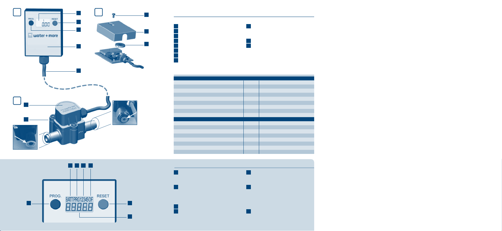
Display (Abb. 1 und Abb. 2)
a. Taste „PROG“
b. Anzeige
c. Taste „RESET“
d. Abdeckung
e. Kabel 1,5 m
f. Schraube
g. Gehäuse
h. Knopfzelle 3VDC, Type CR2032
Sensoreinheit (Abb. 3)
i. Kunststoffgehäuse mit C\," Über-
wurfmutter und
C\," Außen-
gewinde
j. Flachdichtung (ohne Abbildung)
k. Sensor
Hinweis: Hygieneschutz eingangsseitig wie auch ausgangsseitig vor
der Installation entfernen.
1. Lieferumfang Aquameter
2. Technische Daten
Technische Daten Sensoreinheit:
Anschlussgewinde (IN/OUT) [Zoll] 3/8" ÜM × 3/8" AG
Eingangsdruck (min/max) [bar] 2–8 bar
Durchflussleistung [l/h] 10–100
Druckverlust (bis 100 l/h Durchfluss) [bar] 0,2
Durchflussabweichungen [%] +/- 5
Wassertemperatur (min/max) [°C] +4 bis +40
Umgebungstemperatur (min/max) [°C] +4 bis +30
Abmessungen (L×B×H) [mm] 77 × 43 × 46
Einbaulage Horizontal empfohlen
Technische Daten Display extern:
Spritzwasserdicht: IP X4
Statischer Speicher: 5 letzten Nullstellungen
Anzeige: 5 Stellen
Zähler: [l/min] Abwärts von 99999 bis -9999
Einbaulage Horizontal empfohlen
Abmessungen (L×B×H) [mm] 62 × 50 × 17
Kabel: 1,5 Meter, PVC 2 × 0,25 mm²
Bestellnummer Aquameter FS00Y03A00
3. Erläuterung Display-Symbole und Bedeutung
a
b
c
d
e
f
g
h
k
i
l. „PROG“ Taste: – zum Einstellen
– um den Programm Modus zu ver
-
lassen
m. „RESET“ Taste: – Rücksetzen
der Filterkapazität nach jedem best
max Filterkerzen Tausch
– zum Einstellen
n. BATT: Batteriewechsel Anzeige
o. OF: OverFlow Anzeige
Erscheint, wenn der Wert -99999
überschritten wird.
p. PRG: Erscheint, wenn der
water+more Aquameter programmiert
wird
q. 12345: Speicher Info
Es besteht die Möglichkeit, die letz
ten 5 Messungen abzurufen.
Es wird jeweils die Litermenge [L],
wie auch der Zeitraum [t] angezeigt.
r. 5-stellige Anzeige
n p q o
m
r
l
1
3
2

4. Allgemein
Anwendungsbereich
Der water+more Aquameter wurde entwickelt, um die Restkapazität von
water+more Wasserfiltern zu messen und zu kontrollieren. Nach Eingabe (siehe
Abschnitt 6) der jeweiligen Filterkapazität (siehe Einbau- und Bedienungsanleitung
bestmax) errechnet der Aquameter die jeweilige Restkapazität.
Ein rechzeitiger Austausch der water+more Wasserfilter ist damit gewährleistet.
Die eingebaute LCD-Anzeige informiert den Anwender über die Restkapazität der
water+more Wasserfilter.
Sicherheitsvorschriften
1. Lesen Sie diese Bedienungsanlei-
tung vor der Inbetriebnahme aufmerksam durch. Führen Sie alle
Schritte genau nach Anleitung aus.
2. Beachten Sie alle Anweisungen und
Abbildungen.
3. Verwenden Sie nur handelsübliche
Batterien vom Typ CR2032.
4. Beachten Sie, dass der Batterie-De-
ckel korrekt montiert ist. Ansonsten
können Fremdkörper und Nässe eindringen.
5. In folgenden Fällen ist die Stromzufuhr
sofort zu unterbrechen (Batterie entfernen) und ein Techniker zu rufen:
Wasser oder andere Flüssigkeiten
sind in das Gerät eingedrungen
Trotz genauer Befolgung aller in die
Einbauhinweise
keine schnell pulsierende Förderung
des Mediums
keine Druckrückschläge
keine Luft im System
Einbaulage des Aquameter berück
sichtigen
min/max Durchfluss soll im linearen
Bereich des ausgewählten Aquameter liegen
Konformitätserklärung:
Die vorgeschriebenen CE-Richtlinien werden vom water+more Aquameter erfüllt.
ser Bedienungsanleitung angegebenen
Anweisungen funktioniert das Gerät
nicht richtig
Wenn das Gerät herunterfällt und das
Gehäuse beschädigt ist
Wenn die Anzeige des Geräts nicht
funktioniert
Wenn die PROG.- oder die RESET-Tas
te nicht funktioniert
Versuchen Sie auf keinen Fall eigenhändig
etwas zu reparieren oder durch wahlloses
Drücken der PROG.- oder RESET-Taste
etwas zu bewirken.
Ohne Stromversorgung funktioniert die
eingebaute Elektronik nicht. Wird das Gerät ohne bzw. mit erschöpfter Batterie betrieben, ist eine Messung nicht möglich.
-
angemessene periodische Reinigung
Feuchtigkeit bei der Batterie und den
elektrischen Kontakten vermeiden
Induktive Störungen sind zu vermeiden
Die Impulszahl pro Liter kann je nach
-
Medium und Installation abweichen
Wir empfehlen ein Auseichen der Im
pulse/Liter mit der gesamten Instal-
lation
3
-
-
4
5
5. Installation
PROG.
RESET
RESET
PROG.
RESET
RESET
PROG.
Beachten:
Die Wasserzufuhr zum Filtersystem muss unterbrochen sein.
Für die Demontage geeignetes Werkzeug (Gabelschlüssel 19 mm) verwenden.
Die Sensoreinheit mit der im Lieferumfang enthaltenen Flachdichtung (wird in
die Überwurfmutter gelegt) direkt mit dem Filterkopf verschrauben.
Hinweis:
Auf Durchflussrichtung (Pfeil) achten.
Für die Montage geeignetes Werkzeug (Gabelschlüssel 19 mm) verwenden.
Schlauch mit Flachdichtung (wird in die Überwurfmutter gelegt) an die Aus
gangsseite der Sensoreinheit (Pfeilrichtung beachten) befestigen.
Wichtig:
Achten Sie darauf, dass
die Einbaulänge des Aquameters und die Biegeradien der Schläuche einge
halten werden!
die Durchflussrichtung (Kennzeichnung auf dem Filterkopf) eingehalten wird!
die Einbaulage des Messgeräts horizontal ist!
das Gerät keiner mechanischen Belastung ausgesetzt werden darf!
nur Dichtungs- und Verbindungselemente eingesetzt werden, welche für die
vorgesehenen Betriebsbedingungen geeignet sind!
die Rohrleitungen vor und nach dem Gerät abgestützt sind!
das System vor der Inbetriebnahme entlüftet wird!
Sensoreinheit:
Bei einer Neuinstallation befestigen Sie zuerst den
Filterkopf (siehe Einbau- und Bedienungsanleitung „bestmax“ Abschnitt Installation)
Bei einem bereits vorinstalliertem Filtersystem
entfernen Sie den Schlauch an der Ausgangsseite des Filterkopfes, indem Sie die Überwurfmutter lösen.
Display:
Befestigungsmöglichkeiten:
Doppelseitiges Klebeband: (im Lieferumfang nicht
enthalten)
Ein 50 x 40 mm großes Stück Klebeband auf der
Rückseite des Displays befestigen.
Display an gewünschter Position festkleben.
Beachten:
Die zu beklebende Oberfläche muss fett-, staubund schmutzfrei sein.
Schraube: (im Lieferumfang nicht enthalten)
Empfehlung Flachkopfschraube; max. Schaftdurchmesser 4 mm
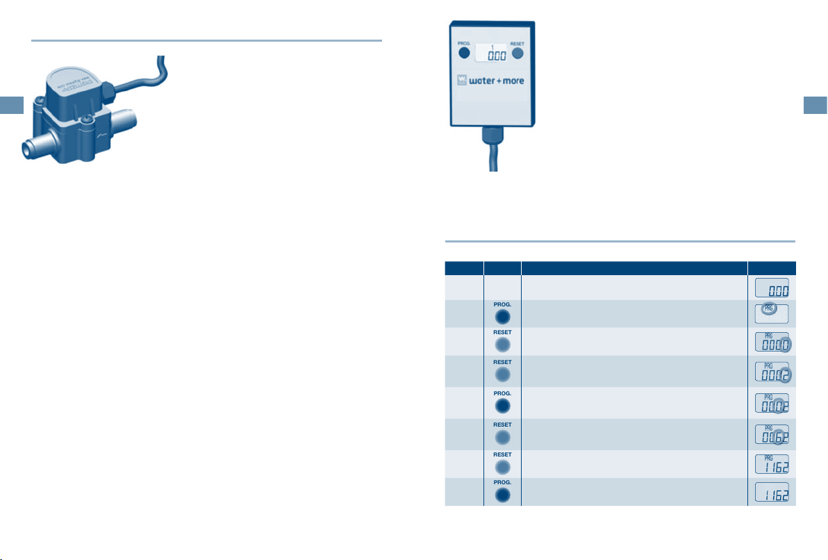
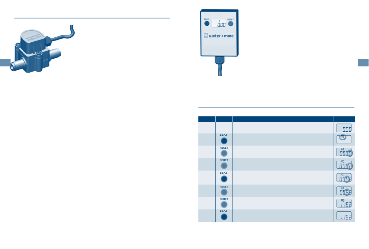
6. Programmierung
Einstellung Filterkapazität:
Schritt Taste Anzeige
1
-
2
3
-
4
5
6
7
Taste „PROG“ einmal drücken
„PROG“ blinkt
Taste „RESET“ einmal drücken
erste Ziffer rechts „0“ blinkt
Durch Drücken der „RESET“ Taste den gewünschten
Wert einstellen.
Für die Zahl „2“, zweimal drücken
Einmal die Taste „PROG“ drücken um zur nächsten
Ziffer zu wechseln
erste Ziffer „0“ blinkt
Durch Drücken der „RESET“ Taste den gewünschten
Wert einstellen.
Für die Zahl „6“, sechsmal drücken
Schritt 4 und 5 wiederholen, bis alle Ziffern eingestellt sind.
Taste „PROG“ einmal drücken
die Filterkapazität ist eingestellt
6
7
PROG.
PROG.
PROG.
PROG.
RESET
PROG.
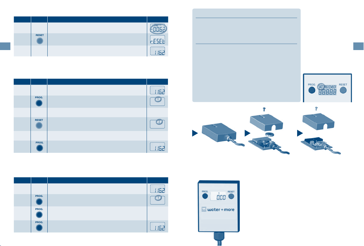
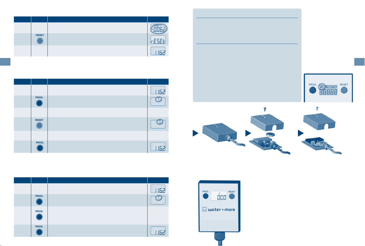
Rücksetzen der Filterkapazität: (nach Wasserfilter-Tausch)
RESET
Schritt Taste Anzeige
bestmax Filterkapazität ist erschöpft
Anzeige blinkt
1
2
Speicherinfo:
Es besteht die Möglichkeit, die letzten 5 Messungen abzurufen.
Es wird jeweils die Litermenge [L], wie auch der Zeitraum [t] angezeigt.
Schritt Taste Anzeige
1
2
3
4
5
Sonderfunktion:
Es kann auch die gesamt Literanzahl (ab Beginn der water+more Aquameter-Installation) ausgelesen werde.
Schritt Taste Anzeige
1
2
3
Taste „RESET“ ca. 3 sec gedrückt halten
am Display erscheint „RESET“
Filterkapazität ist zurückgesetzt
Taste „PROG“ ca. 5 sec gedrückt halten
„1“ blinkt
Am Display erscheint die Litermenge und der Zeitraum
der letzten Messung
Taste „RESET“ einmal drücken
es erscheint die Litermenge und der Zeitraum der
vorletzten Messung
Schritt 3 wiederholen, um die letzten 5 Messungen abzurufen.
Taste „PROG“ einmal drücken
Anzeige der aktuellen Filterkapazität
Taste „PROG“ ca. 5 sec gedrückt halten
„1“ blinkt
Taste „PROG“ noch einmal ca. 5 sec gedrückt halten
es erscheint die Gesamtliterzahl ab Inbetriebnahme
des Aquameters
Taste „PROG“ einmal drücken
Anzeige der aktuellen Filterkapazität
total
7. Gewährleistung
Im Störfall während der Gewährleistungszeit wenden Sie sich bitte an Ihren Vertragspartner.
!
8. Betreiberpflichten
Sie haben ein langlebiges und servicefreundliches
Produkt gekauft. Jedoch benötigt jedes technische
Gerät regelmäßige Servicearbeiten, um die einwandfreie Funktion zu erhalten.
Sensoreinheit: täglich auf Dichtheit prüfen
Batterie: nach ca. 5–7 Jahren gehört die
Batteriewechsel:
Schrauben am Deckel lösen (Kreuzschlitzschraubendreher)
Batterie getauscht. Der notwendige Batteriewechsel wird am
Display mit „BATT“ angezeigt.
Deckel und danach die
leere Batterie entfernen.
Die bis dahin gespeicherten Daten gehen beim
Batteriewechsel nicht verloren.
Neue Batterie (CR2032)
einsetzen (nach unten
drücken)
Auf Polarität achten!
Deckel anschließend mit
der Schraube am Gehäuse befestigen

8
9
1. Aquameter Delivery Scope
Display (fig. 1 and fig. 2)
a. “PROG” button
b. Indicator
c. “RESET” button
d. Covering
e. Cable, 1.5 m
f. Screw
g. Housing
h. Button cell 3VDC, type CR2032
Sensor unit (fig. 3)
i. Plastic housing with C\," nut and
C\," external thread
j. Gasket (no illustration)
k. Sensor
Note: Remove the hygiene protection
on the inlet side and outlet side prior
to installation.
2. Technical Data
Sensor Unit Technical Data:
Connection thread (IN/OUT) [inches] 3/8" nut × 3/8" connection thread
Intake pressure (min/max) [bar] 2–8 bar
Flow capacity [l/h] 10–100
Pressure loss (up to 100 l/h flow rate) [bar] 0.2
Flow rate deviations [%] +/- 5
Water temperature (min/max) [°C] +4 to +40
Ambient temperature (min/max) [°C] +4 to +30
Dimensions (L×W×H) [mm] 77 × 43 × 46
Installation position Horizontal recommended
External Display Technical Data:
Splash water-proof: IP X4
Static memory: 5 most recent null positions
Indicator: 5 digits
Counter: [l/min] Downwards from 99999 to -9999
Installation position Horizontal recommended
Dimensions (L×W×H) [mm] 62 × 50 × 17
Cable: 1.5 metres, PVC 2 × 0.25 mm²
Aquameter order number FS00Y03A00
3. Explanation of Display Symbols and Significance
l. “PROG” button: – for adjusting
settings
– for exiting the Programme mode
m. “RESET” button: – for resetting
the filter capacity after every bestmax
filter cartridge replacement
– for adjusting settings
n. BATT: Battery change indicator
o. OF: OverFlow indicator
Appears when the value of -99999 has
been exceeded.
p. PRG: Appears when the
water+more Aquameter is programmed
q. 12345: Memory information
It is possible to access the 5 most recent measurements.
The capacity in litres [L] and the time
period [t] are displayed for each case.
r. 5-digit indicator
4. General Information
Scope of application
The water+more Aquameter was developed to measure and monitor the residual capacity of water+more water filters. After entry (see Section 6) of the respective filter capacity (see Installation and Operating Instructions bestmax), the Aquameter calculates the relative residual capacity.
This ensures timely replacement of the water+more water filter.
The installed LCD indicator informs the user of the residual capacity of the
water+more water filter.
Safety regulations
1. Read through the Operating Instruc-
tions carefully before the start of operation. Perform all steps exactly as
indicated in the instructions.
2. Adhere to all directions and illustra-
tions.
3. Only use standard batteries of the
type CR2032.
4. Ensure that the battery cover is
properly fitted. Otherwise, debris
and moisture could penetrate.
5. In the following cases, the pow-
er supply must be disconnected immediately (remove battery) and a
technician must be called:
Water or other liquids have pene
trated into the appliance
The appliance does not function prop
erly even though all of the directions
provided in these Operating Instructions
have been adhered to exactly
If the appliance falls and the housing
is damaged
If the indicator of the appliance does
not function
If the PROG or RESET buttons do not
function
Do not attempt to repair anything yourself or to accomplish anything by randomly pressing the PROG or RESET buttons.
If there is no power supply, the installed
electronics assembly will not function. If
-
the appliance is operated without a battery or with a depleted battery, it is not
-
possible to make any measurements.
Installation information
No rapidly pulsating medium stim
ulus
No pressure reversals
No air in the system
Take the installation position of the
Aquameter into account
Min/max. flow rate should lie in the
linear area of the selected Aquameter
Appropriate and periodic cleaning
-
Protect the battery and electrical con
tacts from moisture
Inductive malfunctioning must be
avoided
The number of impulses per litre may
vary according to medium and in-
stallation
We recommend calibration of the im
pulse/litre value with the overall in-
stallation
Self-declaration:
The water+more Aquameter meets the mandatory CE guidelines.
98
-
-
10
11
5. Installation
PROG.
RESET
RESET
PROG.
RESET
RESET
PROG.
Sensor unit:
For initial installation, first attach the filter head
10
Attention:
The water supply to the filter system must be disconnected.
For disassembly, use an appropriate tool (flat wrench, 19 mm).
Screw the sensor unit with the gasket included in delivery (placed in the nut)
directly to the filter head.
Note:
Observe the direction of flow (arrow)
For assembly, use an appropriate tool (flat wrench, 19 mm).
Fasten the hose with gasket (placed in the nut) to the exit side of the sensor
unit (observe the direction of the arrow).
Important:
Ensure that
the installed lengths of the Aquameter and the bending radius of the hoses
are adhered to!
the flow direction (indicated on the filter head) is adhered to!
the measuring unit is installed horizontally!
the appliance is not exposed to any mechanical strain!
sealing and connecting elements are only used if they are suitable for the
provided operating conditions!
the piping is braced in front of and behind the appliance!
the system is ventilated before the start of operation!
(see Installation and Operating Instructions,
“bestmax” installation section)
If a pre-installed filter system is already in place,
remove the hose on the exit side of the filter head
by loosening the nut.
Display:
Fastening options:
Double-sided adhesive tape: (not included in
delivery)
Fasten a 50 x 40 mm piece of adhesive tape to
the rear side of the display.
Fasten the display in the desired position.
Attention:
Fastening must take place on a surface that is free
from grease, dust and dirt.
Screw: (not included in delivery)
Recommendation Flat head screw, max. shaft
diameter 4 mm
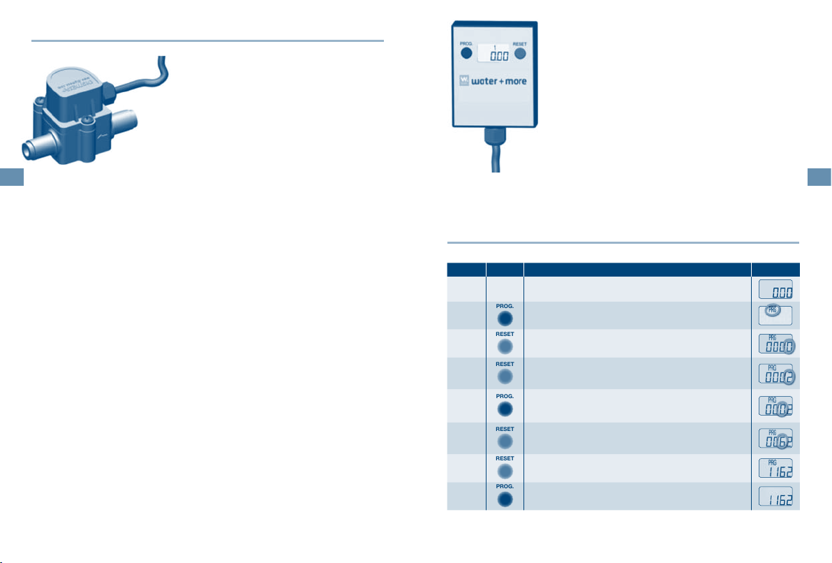
6. Programming
Filter capacity setting:
Step Button Indicator
1
2
3
4
5
6
7
Press the “PROG” button once
“PROG” flashes
Press the “RESET” button once
first digit on the right, “0”, flashes
Set the desired value by pressing the “RESET” button.
For the digit “2”, press two times
Press the “PROG” button once to switch to the next
digit
first digit, “0”, flashes
Set the desired value by pressing the “RESET” button.
For the digit “6”, press six times
Repeat steps 4 and 5 until all digits have been set.
Press the “PROG” button once
The filter capacity is set
12
13
PROG.
PROG.
PROG.
PROG.
RESET
PROG.
Resetting the filter capacity: (after water filter replacement)
RESET
Step Button Indicator
Filter capacity is depleted
Indicator flashes
1
2
Memory information:
It is possible to access the 5 most recent measurements.
The capacity in litres [L] and the time period [t] are displayed for each case.
Step Button Indicator
1
2
3
4
5
Special function:
The overall number of litres (from the beginning of the water+more Aquameter
installation) can also be read out.
Step Button Indicator
1
2
3
Press and hold the “RESET” button for approx. 3 sec.
“RESET” appears in the display
Filter capacity is reset
Press and hold the “PROG” button for approx. 5 sec.
“1” flashes
The display indicates the quantity in litres and the time
period of the last measurement
Press the “RESET” button once
The quantity in litres and the time period of the
next-to-last measurement are indicated
Repeat step 3 to access the 5 most recent measurements.
Press the “PROG” button once
Indication of the current filter capacity
Press and hold the “PROG” button for approx. 5 sec.
“1” flashes
Once again press and hold the “PROG” button for approx. 5 sec.
The overall number of litres from the start of operation
of the Aquameter is indicated
Press the “PROG” button once
Indication of the current filter capacity
total
7. Guarantee
In the event of a fault during the guarantee period,
please contact your contracting partner.
!
8. Operator Duties
You have purchased a long-lasting and servicefriendly product.
However, every technical appliance requires regular
service work to maintain correct functioning.
Sensor unit: check daily for leaks
Battery: the battery must be replaced after
Battery replacement:
Loosen the screws on
the cover (Phillips head
screwdriver)
approx. 5 to 7 years. If the battery
must be replaced, this will be indicated in the display with “BATT”.
Remove the cover, followed by the empty battery.
The data stored up until this time is not lost
when the battery is replaced.
Insert new battery
(CR2032) (press downwards)
Observe the polarity!
Then fasten the cover to the housing using
the screw

14
15
1. Volume de la fourniture Aquameter
Ecran (fig. 1 et fig. 2)
a. Touche « PROG »
b. Affichage
c. Touche « RESET »
d. Recouvrement
e. Câble 1,5 m
f. Vis
g. Boîtier
h. Pile ronde 3V c.c., Type CR2032
2. Caractéristiques techniques
Caractéristiques techniques Module de capteur :
Filetage de raccordement (IN/OUT) [pouces] 3/8" ER x 3/8" FE
Pression d’entrée (mini/maxi) [bars] 2–8 bars
Débit [l/h] 10–100
Perte de pression (jusqu’à 100 l/h de débit) [bars] 0,2
Variations de débit [%] +/- 5
Température de l’eau (mini/maxi) [°C] de +4 à +40
Température ambiante (mini/maxi) [°C] de +4 à +30
Dimensions (L×l×h) [mm] 77 × 43 × 46
Position de montage Position horizontale conseillée
Caractéristiques techniques Ecran externe :
Etanchéité contre les éclaboussures : IP X4
Mémoire statique : 5 dernières positions zéro
Affichage : 5 positions
Compteur : [l/min] descendant de 99999 à -9999
Position de montage Position horizontale conseillée
Dimensions (L×l×h) [mm] 62 × 50 × 17
Câble : 1,5 mètre, PVC 2 × 0,25mm²
Numéro de commande Aquameter FS00Y03A00
Module de capteur (fig. 3)
i. Boîtier en matière plastique avec
écrou-raccord (ER) C\," et C\," filetage extérieur (FE)
j. Joint plat (sans illustration)
k. Capteur
Remarque: avant l’installation, retirer
le dispositif hygiénique côté entrée et
côté sortie.
3. Explication des symboles de l’écran et signification
l. Touche « PROG » : – Pour le rég-
lage
– Pour quitter le mode Programme
m. Touche « RESET » : – Remise à
zéro de la capacité du filtre après chaque remplacement de cartouches filtrantes bestmax
– Pour le réglage
n. BATT: Affichage de remplacement
de la batterie
o. OF: Affichage d’OverFlow
Apparaît lorsque la valeur 99999 est
dépassée.
p. PRG: Apparaît lorsque
l’Aquameter water+more est en cours
de programmation.
q. 12345: Info Mémoire
Il est possible d’appeler les 5 dernières
valeurs mesurées.
La quantité en litre [L], ainsi que la période de temps [t] sont affichées.
r. Affichage 5 positions
4. Généralités
Domaine d’application
L’Aquameter water+more a été développé pour mesurer et contrôler la capacité
résiduelle des filtres à eau water+more.
Après introduction (voir paragraphe 6) de la capacité du filtre (voir Instructions de
montage et d’emploi bestmax), l’Aquameter calcule la capacité résiduelle correspondante. Ce qui garantit le remplacement en temps voulu du filtre à eau water+more.
L’affichage LCD intégré informe l’utilisateur de la capacité résiduelle du filtre à eau
water+more.
Consignes de sécurité
1. Veuillez lire avec soin les présentes
instructions d’emploi avant la mise en
service. Effectuez toutes les opérations en suivant exactement les instructions.
2. Tenez compte de toutes les instruc-
tions et illustrations.
3. N’utilisez que des piles vendues dans
le commerce du type CR2032.
4. Veillez à ce que le couvercle de la bat-
terie soit monté correctement. Sinon,
des corps étrangers et de l’humidité
risqueraient d’y pénétrer.
5. Dans les cas suivants, interrompre im-
médiatement l’alimentation en courant
(retirer la pile) et appeler un technicien.
De l’eau ou d’autres liquides ont pé
nétré dans l’appareil.
Instructions de montage
Pas de refoulement pulsatoire rapi
de du fluide
Pas de coups de bélier
Pas d’air dans le système
Tenir compte de la position de mon
tage de l’Aquameter
Le débit mini/maxi doit se trouver
dans la plage linéaire de l’Aquameter sélectionné
Déclaration de conformité
Les directives CE imposées sont respectées par l’Aquameter water+more.
Malgré le respect de toutes les instruc
tions énoncées dans le présent mode
d’emploi, l’appareil ne fonctionne pas
correctement.
Si l’appareil tombe et que le boîtier est
endommagé
Si l’affichage de l’appareil ne fonction
ne pas
Si la touche PROG. ou la touche RESET
ne fonctionne pas
N’essayez jamais de réparer quelque chose par vos propres moyens ou d’obtenir un
résultat en appuyant arbitrairement sur la
touche PROG. ou RESET.
L’électronique intégrée ne fonctionne pas
sans alimentation en courant électrique. Si
-
l’appareil est utilisé sans pile ou avec une
pile usagée, la mesure est impossible.
-
Nettoyage périodique adéquat
Eviter l’humidité sur la pile et les
contacts électriques
Eviter les perturbations inductives
Le nombre d’impulsions par litre
-
peut varier en fonction du fluide et
de l’installation
Nous conseillons l’étalonnage des
impulsions/litre de l’ensemble de
l’installation
-
15
-
16
17
5. Installation
PROG.
RESET
RESET
PROG.
RESET
RESET
PROG.
Module de capteur :
Lors d’une nouvelle installation, fixer tout d’abord
la tête de filtre (voir les Instructions de montage et
d’emploi « bestmax » paragraphe Installation)
En cas de système de filtre pré-installé, retirer le
Attention :
couper l’arrivée d’eau vers le système de filtre.
utiliser un outil approprié au démontage (clé à fourche de 19 mm).
Visser directement le module de capteur à la tête de filtre avec le joint plat (à
introduire dans l’écrou-raccord) compris dans la fourniture.
Remarque :
tenir compte de la direction du flux (flèche).
utiliser un outil approprié au montage (clé à fourche de 19 mm).
Fixer le flexible avec le joint plat (à introduire dans l’écrou-raccord) sur le côté
sortie du module de capteur (tenir compte de la flèche).
Important :
veiller à ce que
la longueur de montage de l’Aquameter et les rayons de courbure des flexi
bles soient respectés
la direction du flux (repère sur la tête du filtre) soit respectée
l’appareil de mesure soit monté en position horizontale
l’appareil ne soit pas exposé à des sollicitations mécaniques
seuls soient employés des joints et des raccords appropriés aux conditions
de fonctionnement prévues
les conduites situées en amont et en aval de l’appareil soient étayées
le système soit purgé avant la mise en service
flexible placé du côté sortie sur la tête de filtre en
desserrant l’écrou-raccord.
Ecran :
Possibilités de fixation :
Ruban adhésif double face : (non compris dans le
volume de la fourniture)
Placer un grand morceau de ruban adhésif 50 x
40 mm au dos de l’écran.
Fixer l’écran à la position souhaitée.
Attention :
la surface d’encollage doit être dégraissée, exempte
de poussière et propre.
Vis : (non comprise dans la fourniture)
Recommandation vis à tête plate ; diamètre maxi
de la tige 4 mm
6. Programmation
Réglage Capacité du filtre :
Etape Touche Affichage
1
2
3
-
4
5
6
7
Appuyer une fois sur la touche « PROG »
« PROG » clignote
Appuyer une fois sur la touche « RESET »
le premier chiffre de droite « 0 » clignote
En appuyant sur la touche « RESET », régler la valeur
souhaitée.
Appuyer deux fois pour obtenir le chiffre « 2 »
Appuyer une fois sur la touche « PROG » pour passer
au chiffre suivant
le premier chiffre « 0 » clignote
En appuyant sur la touche « RESET », régler la valeur
souhaitée.
Appuyer six fois pour obtenir le chiffre « 6 »
Répéter l’étape 4 et 5 jusqu’à ce que tous les chiffres
soient programmés.
Appuyer une fois sur la touche « PROG »
la capacité du filtre est réglée
 Loading...