

WB
L
I
S
T
E
D
®
OPERATOR’S MANUAL
■ WB-50A ■ WB-120A
1.103-474.0 1.103-473.0
For technical assistance or the Water Maze Dealer nearest you consult our web page at
www.wmaze.com
07/11/19 8.913-984.0-L

CONTENTS
Introduction .................................................................................................................................... 4
Unpacking ...................................................................................................................................... 4
General Safety Instructions ....................................................................................................... 4, 5
Electrical Safety Information .......................................................................................................... 5
Wiring ........................................................................................................................................ 5, 6
Pump Safety .................................................................................................................................. 6
Standard Safety Features .......................................................................................................... 6, 7
Installation.................................................................................................................................. 7, 8
Pre-Startup Check List .................................................................................................................. 8
Operating Procedure ..................................................................................................................... 9
Principles of Operation .................................................................................................................. 9
Installation Drawings ............................................................................................................. 10 - 11
Storage Tank Configuration .........................................................................................................12
Exhaust Stacking Configuration ................................................................................................... 13
WB-50A Front View ...................................................................................................................... 14
WB-120A Front View .................................................................................................................... 15
Start-Up Procedures .................................................................................................................... 16
Shut Down Procedures ................................................................................................................ 16
Setting the Burner ........................................................................................................................ 17
Soft Start Ignition ......................................................................................................................... 17
Burner Adjustment Diagram ........................................................................................................ 18
Foaming ....................................................................................................................................... 19
Converting Natural Gas to L.P. Gas ............................................................................................. 19
Veri-Flame #7-8061 ..................................................................................................................... 20
3 Point Sensor Control ................................................................................................................. 20
Setting High Limit Control ............................................................................................................ 21
Maintenance ........................................................................................................................... 21-23
WB • #8.913-984.0-L

CONTENTS
Programming of Water Maze Cycle Timer .............................................................................. 24-26
Water Level Control Unit & Parts List .......................................................................................... 27
WB-50A Exploded View .......................................................................................................... 28-29
WB-50A Exploded View Parts List .......................................................................................... 30-32
WB Control Panel w/Parts list ................................................................................................. 33-35
WB-120A Exploded View ........................................................................................................ 36-37
WB-120A Exploded View Parts List ........................................................................................ 38-40
Water Maze w/Anti-Foam Metering Pump .................................................................................. 41
Air Line Assembly Exploded View and Parts List ...................................................................42-43
Gas Train Assembly WB-50 Exploded View and Parts List ..................................................... 44-45
3
Gas Train Assembly WB-120 Exploded View and Parts List ................................................... 46-47
Replacing Pump Head Tubing .................................................................................................... 48
Metering Pump and Parts List ..................................................................................................... 49
Peristaltic Metering Pump ............................................................................................................ 48
WB-50/120 Regenerative Blower #5-1503 ..................................................................................49
Troubleshooting ...................................................................................................................... 52-54
Specifications ............................................................................................................................... 55
Service Log .................................................................................................................................. 56
Warranty ......................................................................................................................................57
Model Number ______________________________
Serial Number ______________________________
Date of Purchase ____________________________
The model and serial numbers will be found on a decal attached
to the evaporator. You should record both serial number and date
of purchase and keep in a safe place for future reference.
WB • 8.913-984.0-L
WATERMAZE SERIES OPERATOR’S MANUAL
WARNING
WARNING
4
INTRODUCTION
Your owner's manual has been prepared to provide
you with a simple and understandable guide for equipment operations and maintenance based on the latest
product information available at the time of printing. To
keep your machine in top running condition, follow the
specific maintenance and trouble shooting procedures
given in this manual.
NOTE: WATER MAZE reserves the right to make chang-
es at any time without incurring any obligations
UNPACKING
1. WATER MAZE module with removable doors
2. 20 mesh filter screen in a plastic housing
3. Tube of caulk
4. Operator's manual
5. WATER MAZE tool kit and door removal tool
6. WATER MAZE 5600 Defoamer
7. Bulk head fitting and strain relief
NOTE: Report any damage to machine or components
for claim against the freight line.
Owner/User Responsibility:
The owner and/or user must have an understanding
of the manufacturer’s operating instructions and warnings before using this WATER MAZE machine. Warning
information should be emphasized and understood. If
the operator is not fluent in English, the manufacturer’s
instructions and warnings shall be read to and discussed
with the operator in the operator’s native language by
the purchaser/owner, making sure that the operator
comprehends its contents.
Owner and/or user must study and maintain for future
reference the manufacturers’ instructions.
SAVE THESE INSTRUCTIONS
This manual should be considered a permanent
part of the machine and should remain with it if
machine is resold.
When ordering parts, please specify model and serial number. Use only identical replacement parts.
This machine is to be used only by trained operators.
PLEASE NOTE: WATER MAZE is not responsible for
procurement of regulatory and/or operating permits that
may be required by city, county, state or federal agencies. It is the customer who is responsible for procurement of any hazardous or non-hazardous regulatory
and/or operating permits, compliance with codes or
other governmental requirements associated with the
installation, use, or disposal of waste associated with this
equipment. Submerged combustion can be classified as
WB • 8.913-984.0-L
incineration in specific jurisdictions. It is the customer's
responsibility for procurement of appropriate local and
state permits as needed.
The guidelines listed in the evaporator feasibility report
are specific only to the waste stream submitted for evaluation and estimated emissions. Moreover, WATER MAZE
is not reponsible for the operation or maintenance of
the evaporator unit. If the unit is subjected to any waste
stream other than that which has been tested by the
named laboratory, operation may cause adverse effects
on the equipment and will negate any warranty of parts
or equipment.
IMPORTANT SAFETY
INSTRUCTIONS
WARNING: To reduce the risk of
injury, read operating instructions carefully before using.
1. Read the owner's manual
thoroughly. Failure to follow
READ OPERATOR’S
MANUAL
THOROUGHLY
PRIOR TO USE.
2. The installation of the gas line must be done by a
licensed gas contractor and in accordance with local
and/or national codes.
DANGER
HAZARDOUS
VOLTAGE. CAN
SHOCK, BURN OR
CAUSE DEATH.
chine while it is in operation except those prescribed
in this manual.
4. Do not allow high concentrations of flammable fluids,
acids, caustic or abrasive fluids to pass through the
waste water pump into the combustion chamber.
5. Before servicing this machine, refer to all the MSDS
on the material identified in the waste stream. You
DANGEROUS FUMES:
INSTALL ONLY IN
WELL VENTILATED
AREA .
the instructions could cause a
malfunction of the machine and
result in death, serious injury
and/or property damage.
DANGER: The machine, when
installed, must be electrically
grounded in accordance with local and/or national codes. Do not
spray water near electrical components. Do not touch machine
with wet hands or while standing
in water.
3. Never make adjustments on ma-
must comply with all warnings and
wear all protective clothing stated
on the MSDS.
WARNING: Avoid installing machines in small confined areas.
Adequate oxygen is needed for
combustion or dangerous carbon
monoxide will result.
WATERMAZE SERIES OPERATOR’S MANUAL
WARNING
WARNING
5
6. Protect inlet hoses from traffic and sharp objects.
7. Be certain hoses and piping have been connected
before operating.
8. Turn the machine off before disconnecting hoses.
9. Inlet influent temperature must not exceed 150°F
(66°C).
10. When making repairs, disconnect the machine from
the electrical source.
11. The best insurance against an accident is precaution
and knowledge of the equipment.
12. WATER MAZE is not liable for any modifications or
the use of components not purchased from WATER
MAZE.
13. The WATER MAZE and components will freeze if
not in operation and must be located in a heated
enclosure in cold climates.
14. Running the system or the pump without water will
damage the pump and will void the warranty.
15. WATER MAZE should be installed and started up
by an authorized WATER MAZE dealer.
16. This machine can be used with natural gas or
propane. A conversion kit can be supplied by the
manufacturer to convert the machine to the alternate
fuel.
WARNING: If you smell gas, shut
off the gas supply valve, extinguish any open flame and test all
joints with a soap solution. If the
odor persists, call your gas sup-
RISK OF FIRE OR
EXPLOSION:
AVOID FLAMMABLE
LIQUIDS, VAPORS
OR SOLIDS.
plier immediately.
WARNING: Do not locate the machine in the vicinity of any flammable vapors, liquids or solids.
17. Only those liquid wastes that have been approved by
WATER MAZE and the proper regulatory agencies
should be placed in the WATER MAZE machine.
EPA test methods 8260 and 200.7 must be obtained.
NOTE: If any other liquids that have not been tested
are introduced into the WATER MAZE machine, the
warranty will be void.
18. WARNING: Do not attempt to evaporate flam-
mable wastes of any kind, i.e., do not process
solvents, pure oils, etc.
19. WATER MAZE requires a representative sample
of the waste stream analyzed for pH, metals, total
solids, total suspended solids, oil and grease, foam
and chlorides test.
20. High levels of chlorides and fluorides will cause corrosion especially when heated.
ELECTRICAL SAFETY
INFORMATION
WARNING: To reduce the risk of
injury, read electrical instructions
carefully before using.
WARNING: Do not bypass any
safety feature. You can cause
RISK OF FIRE OR
EXPLOSION:
OBEY SAFETY IN-
STRUCTIONS.
DANGER
fires and explosions. Obey the
safety precautions in safety
instructions.
DANGER: Hazardous voltage
can shock, burn or cause death.
Ground machine before connecting to power supply.
1. Ground the equipment before
HAZARDOUS
VOLTAGE. CAN
SHOCK, BURN OR
CAUSE DEATH.
connecting it to an electrical
power supply.
2. Failure to ground the equipment can cause a severe or
fatal electrical shock hazard.
3. Do not ground to a gas supply line.
4. To avoid dangerous or fatal electrical shock, turn
OFF the power to the equipment before working on
the electrical connections.
5. Supply voltage must be within ± 10% of the nameplate voltage. Incorrect voltage can cause a fire
or seriously damage the equipment and voids the
warranty. If in doubt, consult a licensed electrician.
6. Connect the equipment to a dedicated circuit with
no other equipment on it.
WIRING
1. Install a ground wire and maintain this equipment
in accordance with your local electrical code and all
other codes and ordinances that apply. Consult your
local building inspector for local code information.
2. Ground the equipment permanently using a wire
of size and type specified by local and/or National
Electrical Code.
3. Connect the ground wire first to the green grounding wire provided. Do not connect the equipment
to an electrical power supply until the machine is
permanently grounded, otherwise serious or fatal
electrical shock hazard may be caused.
4.
For the best ground connection, connect to a grounded lead in the service panel or to a metal underground
water pipe or well casing at least 10 feet long. If plastic
pipe or insulated fittings are used, run the ground
wire directly to the metal well casing or use ground
electrode furnished by the power company.
WB • 8.913-984.0-L

WATERMAZE SERIES OPERATOR’S MANUAL
WARNING
6
5.
If 208V single phase is the only available electrical
source, the step down transformer must be changed to
a 208/120V .500KVA transformer or a buck boost transformer must be installed to raise the voltage to 230V.
PUMP SAFETY
WARNING: Do not pump high
concentrations of flammable
liquids or explosives such as
gasoline, fuel oil, kerosene, etc.
Do not use in explosive atmo-
RISK OF FIRE OR
EXPLOSION:
OBEY SAFETY
INSTRUCTIONS.
warning could result in personal injury and/or property damage.
1. Know the pump application, limitations and potential
hazards.
2. Make certain that the power source conforms to the
requirements of your machine; 230V single phase
for all WATER MAZE machines. Always check the
serial plate for power requirements.
3. Release all pressure within the system before servicing any component.
4. Drain all liquids from the components before
servicing.
5. Check hoses for weak or worn condition before each
use, making certain all connections are secure.
6. Periodically inspect sparger tube, nozzle, filter and
other system components. Perform routine maintenance as required.
Personal Safety:
a. Keep work area clean, uncluttered and properly
lit. Replace all unused tools and equipment.
b. Keep visitors at a safe distance from the work
area.
c. Make the workshop safe with padlocks, master
switches and power lock out devices.
7. All wiring and electrical connections must be performed by a qualified electrician.
8. Protect the electrical cord by having the electrician
run all electrical wiring through conduit from the
power source to the machine.
9. Use wire of adequate size to minimize a voltage drop
at the motor.
10. Disconnect the power before servicing a motor or
other components. If the power disconnect is out-of-
sight, lock it in the open position and tag it to prevent
unexpected application of power.
spheres. The Water Maze should
only be used with liquids compatible with Water Maze component
materials. Failure to follow this
11. Do not touch an operating motor. Modern motors
are designed to operate at high temperatures.
STANDARD SAFETY FEATURES
The WATER MAZE uses electricity, gas and water to
operate. These can be fatal if not handled properly. For
this reason, the WATER MAZE has been designed with
safety in mind. The following are standard safety features
you will find on all WATER MAZE equipment.
Interlock System:
The WATER MAZE has an interlock system which must
be proven before the burner will ignite. All of these interlocks are proven through the Veri-Flame.
1. Pre-Ignition Interlocks:
a. High/low gas pressure switches
These switches insure that there is enough gas
pressure to operate the burner but not excessive
pressure (see page 20).
NOTE: The low pressure switch is set at 12 water
column inches (wci). The high pressure switch
is set at 60 water column inches (wci).
b. Air Pressure Switch
This switch insures there is at least 12 water
column inches of air pressure. NOTE: The High,
Low Gas and Air Pressure Switches have internal lights. If there is a failure, the light goes out.
See pages 43 & 45.
c. Gas Solenoid Valve
This valve must be closed during pre-ignition
checks. If open, the system will shut down.
NOTE: The WB-50 has three gas solenoid
valves. The WB-120 has six gas solenoid valves
(see pages 43-45).
d. 3 Point Sensor Control:
The evaporation tank must have a minimum
amount of water to prevent damage to internal
parts due to excessive heat. If the water level is
at the bottom rod on the 3 Point Sensor Control,
ignition of the burner is prevented (see item 3
page 27).
2. Post-Ignition Interlock:
UV Scanner
A UV scanner looks for the ignition of the burner.
Once the WATER MAZE has gone through the inter-
locks and the 15 second purge process, the burner
goes through an ignition sequence. If the burner fails
to ignite, the UV scanner shuts down the burner.
Filter:
A 20 mesh screen on the incoming waste water line
prevents solids from entering and damaging the pump.
WB • 8.913-984.0-L
WATERMAZE SERIES OPERATOR’S MANUAL
WARNING
7
Control Rod:
Automatic wastewater control set points on the 3 Point
Level Controller turns the wastewater air pump on and
off to control the water level inside the evaporator. The
controller also shuts burner off if water level gets to low.
Temperature Control:
Dual, manual reset, and high temperature controls
monitor the internal temperature of the evaporator. If the
exhaust or water temperatures become too high (225°F)
the system shuts down. The temperature is usually in
the 180° to 190° range.
Regulator Venting:
A pressure regulator gas vent is provided. The gas vent
needs to be plumbed to the atmosphere. If the gas
regulator fails, the gas is automatically vented outside, preventing a gas buildup in the location of the
WATER MAZE. This must be vented to comply with
local and/or national codes.
Demister Box:
The demister box contains screens inside that prevent
large water droplets from going up the stack (screen
hole size is 3/16").
INSTALLATION
Location:
Locate the WATER MAZE evaporator on a level con-
crete surface in a room that is well ventilated. Protect the
machine from damaging environment such as wind, rain
and freezing temperatures. Leveling feet are provided
with all evaporators.
CAUTION: For natural gas, air ventilation should
be located near the ceiling. For liquid propane, air
ventilation should be located near the floor.
Gas:
The WATER MAZE evaporator is available for operation
in natural gas or liquid propane.
CAUTION: There are major differences in the adjustments of the evaporators. Do not try to operate the
machine using the wrong gas.
The one inch (1") gas supply line on the WB-25, and
WB-50 and (one and one half inch (1-1/2") on the
WB-120) must have a minimum of 2 psig and a maximum of 10 psig and be of adequate size to supply the
necessary volume for proper burner operation. The high/
low gas switches require between 12-60 water column
inches. There must be a main gas shut-off valve (not provided) in the gas supply line located next to the WATER
MAZE which can be used as an emergency shut off for
repair or maintenance purposes.
WB • 8.913-984.0-L
WARNING: The gas line must be
installed by qualified personnel only. It must be checked for
leaks before installing the WATER
MAZE. All gas piping must comply with local and national fuel
GAS LINE MUST
BE INSTALLED BY
QUALIFIED
PERSONNEL ONLY.
“Natural Gas Only” or “L.P. Gas Only” depending on the
machine you purchase. Connect the vent line to the 1"
vent pipe on the rear panel of the WATER MAZE (see
figures 1-3).
CAUTION: This vent pipe must be vented to the atmosphere.
gas codes.
Connect the main gas line to the 1"
or 1-1/2" line on the rear panel of the
WATER MAZE. This will be labeled
Electrical:
The WATER MAZE requires 230 volts single phase. Re-
fer to the serial plate for proper voltage and amp requirements for your machine. All electrical lines must be tested
with a voltage meter for proper voltage before connecting to the WATER MAZE. NOTE: If 208V single phase
is the only electrical source available, the step down
transformer must be changed to a 208/120V transformer
(#6-60011) or a buck boost transformer must be used
to increase the voltage.
DANGER
HAZARDOUS
VOLTAGE. CAN
SHOCK, BURN OR
CAUSE DEATH.
rear panel conduit box using a 1/2" knock-out. Electrical
conduit must be run all the way to the connection point
in accordance with local codes.
DANGER: All electrical lines must
be installed by qualified personnel only. All installations must
be electrically grounded and
conform to all local and national
electrical codes. Water Maze is
ETL listed.
The electrical connection for the
WATER MAZE is located on the
Fresh Water:
During initial start up, we recommend using fresh water in
the wastewater tank. Fill to mark indicated on sight tube
and remove garden hose. Connect the garden hose to the
WATER MAZE at the female connector located on the 3
point level controller. Open valve partially so back pressure doesn't fill up sight glass tube.
Wastewater:
Wastewater is drawn directly into the evaporator using
the air pump supplied. A 20 mesh stainless steel filter
protects the pump from debris. The connection between
the above ground waste water tank and the machine is
made by using a 3/4" I.D. supply hose with common

WATERMAZE SERIES OPERATOR’S MANUAL
8
connectors supplied by the customer and is located on
the rear panel with the label, “Wastewater Inlet" (see
page 11). NOTE: The WATER MAZE is automatically
controlled by the 3 point level controller and will supply
wastewater as needed after startup.
CAUTION: Foaming detergents will affect the
evaporation process in the WATER MAZE. An
anti-foaming kit has been installed to control foam.
Venting:
Each evaporator must have its own vent stack. A 10"
vent pipe (WB-50) must be installed using the provided
exhaust stack adapter to the machine's exhaust stack
and be vented to the atmosphere. A 12" pipe must
be used for the WB-120 (see figure 4). The top of the
exhaust stack should be sufficiently above the roof to
allow for proper dispersion of the exhaust. It should be
unobstructed and in compliance with all local and federal
codes. Avoid bends if possible.
NOTE: If possible, the stack should be a single piece.
CPVC is the recommended stack material. If it has
seams, the seams must be sealed with a duct sealant
to prevent moisture leaks since the exhaust is 100%
saturated air. All stacking must be installed by qualified
personnel only.
NOTE: Exhaust stacking must be water tight.
A straight stack is always the best. If you must have
bends, use 45° not 90° elbows. No more than two bends
should be used. A vertical discharge design is our ONLY
recommendation for a rain cover. A vertical rain cover is
an over-sized piece of stack material that is concentric
with the stack. The cover extends 6" down over the top
of the stack to allow flexibility in positioning fasteners.
Both rain protection and back pressure reduction are
achieved with this design. It works because rain never
falls straight down; it always falls at an angle. Therefore,
the cover is made long enough so that any rain will hit the
cover’s inside wall. Rain then runs down the inner wall
and out the angular opening at the top of the exhaust
stack (see page 13).
Air:
Connect air to regulator, adjust to 60-100 psi at 10 cfm
PRE-STARTUP CHECK LIST
Follow all pre-start procedures before attempting to start
the WATER MAZE.
1.
Level evaporator using leveling feet or anchor machine to floor. Anchoring to floor is the preferred
method.
2. Verify the voltage, then connect the electrical lines
to the machine. To be done by qualified personnel.
3. Leak test connected gas line.
WB • 8.913-984.0-L
4. Connect the wastewater line from the storage
tank.
NOTE: the pH of the wastewater should be kept
between 8 - 10 in the storage tank.
5. Attach (black) N/O float inside wastewater tank just
above outlet so fill pump doesn't suck air.
6. Attach a high heat hose (180°-190°F) to the 3/4"
stainless steel elbow located at the back side of
evaporator for the auto purge cycle. NOTE: Do not
send waste back to fill tank.
7. Attach the stack to the exhaust stack flange.
8. Remove the plugs from the brass orifices on the
gas and air line and install the test valves with the
brass hose barb fittings (not included). (See page
18.) Make sure the gas line is shut off.
NOTE: The valves, fittings, and manometers are
included in the WATER MAZE set-up kit, #7-8200,
which must be purchased separately.
9. Connect the high pressure port of the 0 to 50 manometer to the bottom gas orifice port and open the
gas line.
NOTE: Make sure the manometer is zeroed before
taking readings. Use the zero set screw at the bottom of the manometer. This will give you the static
gas pressure. For measuring the static gas pressure
on the WB-50/120, use the valve at the bottom of
the machine next to the high gas pressure switch
(see page 18). This pressure should be 45 water
column inches (wci). Close the valve and remove
the manometer. You must have between 12 and 60
wci before the high/low gas switches will allow the
burner to ignite.
10. Connect the 0 to 10 manometer to the hose barbs
on the gas line and open the valves with the low
pressure port of the manometer to the top port of
the orifice and the high pressure port to the bottom
port of the orifice. This will give you the pressure differential between the high side, before the orifice,
and the low side, after the orifice. This will be used
later to figure the evaporation rate and to balance
the burner. This reading will be taken after start up
.
when the burner is being used (see page 18).
NOTE: Items 8 through 10 have been set at the
factory but installation conditions change so adjustments need to be verified.
11. Open the valve on gas line and wastewater line.
12. Connect purge hose to bottom of combustion tank
and run to a separate holding tank. Do not connect
to feed tank.
13. Connect air.
14. Adjust anti-foam air to 2 psi and UV scanner air to
1/2 psi.

WATERMAZE SERIES OPERATOR’S MANUAL
9
OPERATING PROCEDURE
First, collect the waste stream. This can be accomplished
with the use of a catch basin, collection pit, sump or any
other process which collects the waste stream in one
location. The collection method should allow for oil and
solids separation. The waste stream must be stored in
an above ground tank to provide a gravity feed situation
to the waste stream pump of the evaporator. The WATER
MAZE air diaphragm pumps are self priming but we do
recommend a positive feed system (see figure 3).
1. A fresh water source is connected to the evaporator
for the initial fill. The evaporator must have a minimum amount of water before it will operate.
2. With the gas line, gas vent, exhaust vent and electrical connected and main disconnect turned on,
push the reset button F1/RST on the timer. NOTE:
Whenever the power to the evaporator goes out, the
reset button F1/RST on the timer must be pushed.
3. Turn the blower switch to the automatic position. This
will engage the blower which will push the water out
of the sparger tube. This causes the water level to
rise slightly in the liquid level float assembly. If the
low water light is still illuminated, attach a garden
hose to the back of the machine and fill the tank
until the light goes out. Now it is time to turn on the
burner.
4. Turn the burner switch to the on position. The system
now goes through the interlocks, 1) high/low gas
pressure; 2) air pressure; 3) closed gas solenoid,
4) low water, bottom setpoint on the 3 point level
control rod. Now a purge cycle will purge the sparger
tube with air for 15 seconds to insure that there is no
gas in the sparger tube. The burner then attempts
to ignite the soft start pilot flame. If there is not an
ignition, the UV scanner shuts the system down and
the start up sequence must be started over.
5. Once the burner ignites, the waste pump switch
can be turned on to introduce wastewater into the
evaporator. This will add wastewater to the system
through the back of the tank.
NOTE: The heat from the burner goes through the
sparger tube and out a slot in the bottom of the
sparger tube, and finally, into the surrounding water.
There are five stainless steel screens on a WB-50
and ten on the WB-120, that break down the size
of bubbles (from big to small) which increases the
surface area and transfers virtually 100% of their
heat to the water to increase saturation (screen hole
size is 1/16").
Auto Purge:
The unit will automatically purge the waste stream from
the combustion chamber at a set time depending on
your waste stream. This purged waste stream must
be sent to an appropriate discharge holding tank and
not back to the feed or inlet holding tank going to
WATER MAZE.
PRINCIPLES OF OPERATION
The WATER MAZE evaporator is designed to evaporate
wastewater. WATER MAZE uses a unique method of
introducing the wastewater directly into a 2000°F flame.
Using submerged combustion technology, the WATER
MAZE can obtain virtually a 100% heat transfer for a
more efficient and less costly method of evaporation.
In order to understand how this system works and why
it is superior to any other evaporator on the market, it is
important to understand a few aspects of relative humidity, submerged combustion and efficiency ratings of this
type of equipment.
First, relative humidity is called “relative” because the
amount of moisture a given amount of air can hold is
directly related to its temperature. For example, let's say
it's snowing. If you were to take a cubic foot of outside
air at 20° F, with a relative humidity of 100% and bring
this air inside and warm it up to 72°F; the same air would
have the same amount of moisture in it, but would have
a relative humidity of only 15%. The warmer the air is,
the more moisture it can hold. With regard to the WATER
MAZE, this "thirst" or affinity for moisture in hotter air is
especially dramatic at temperatures above 150°F.
Second, it will be of value for you to be familiar with some
basics of water heating and evaporation. All of this type
of equipment will be rated in terms of British thermal
units (BTU's) per hour.
A BTU is the amount of heat necessary to raise one
pound of water one degree Fahrenheit.
Let's say we want to evaporate one pound of water:
In order to get our pound of water from 60°F to 212°F,
we will have to add 152 BTU's to it (212°F minus 60°F).
This is called “sensible” heat.
Once this pound of water reaches 212°F, 970 BTU's must
then be applied to turn it into a pound of steam vapor still
at 212°F. We just want to change it from liquid water to
steam vapor and not raise the temperature at all. This
is called “latent” heat.
Therefore, to get our pound of 60°F water to 212°F
steam took 1122 BTU's.
A gallon of water weighs 8.34 pounds. In order to make
a gallon of water evaporate, we have to subject it to 8.34
lbs. x 1122 BTU's or, 9357 BTU's.
WB • 8.913-984.0-L
WATERMAZE SERIES OPERATOR’S MANUAL
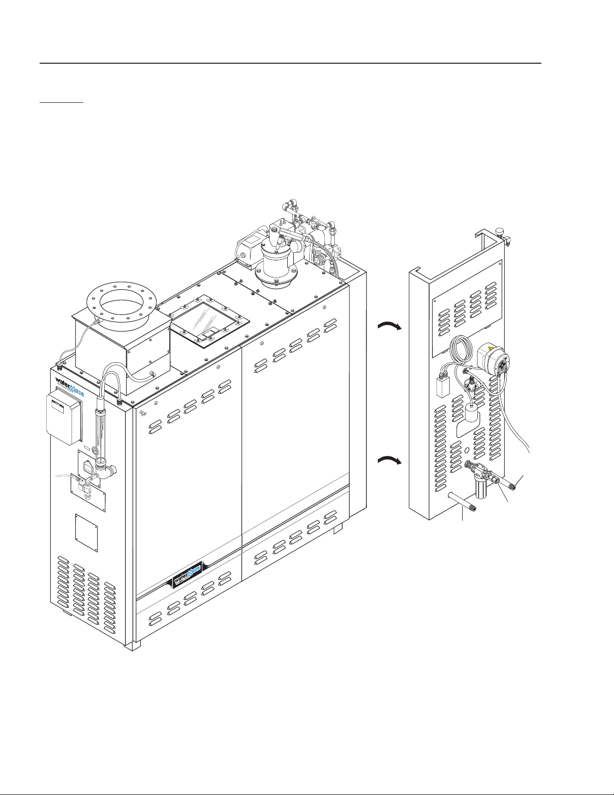
10
WB-50
INSTALLATION DRAWING
Figure 1
1" Inlet
Gas Line
Vent
Pipe
Wastewater
Inlet
WB • 8.913-984.0-L

WATERMAZE SERIES OPERATOR’S MANUAL
WB-120
INSTALLATION DRAWING
11
Auto Purge
Port
1-1/2"
Inlet Gas
Line
Vent
Pipe
Wastewater
Inlet
Figure 2
WB • 8.913-984.0-L
WATERMAZE SERIES OPERATOR’S MANUAL
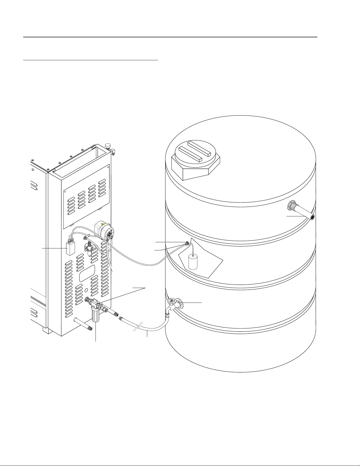
12
STORAGE TANK CONFIGURATION
Wastewater
Storage Tank
Junction
Box
Filter
Housing
Wastewater Inlet
Bulkhead
Strain
Relief
Float
Switch
Inline
Filter
Wastewater
Shut-Off Valve
(Customer Supplied)
Wastewater
Inlet Connection
(Customer Supplied)
Figure 3
WB • 8.913-984.0-L
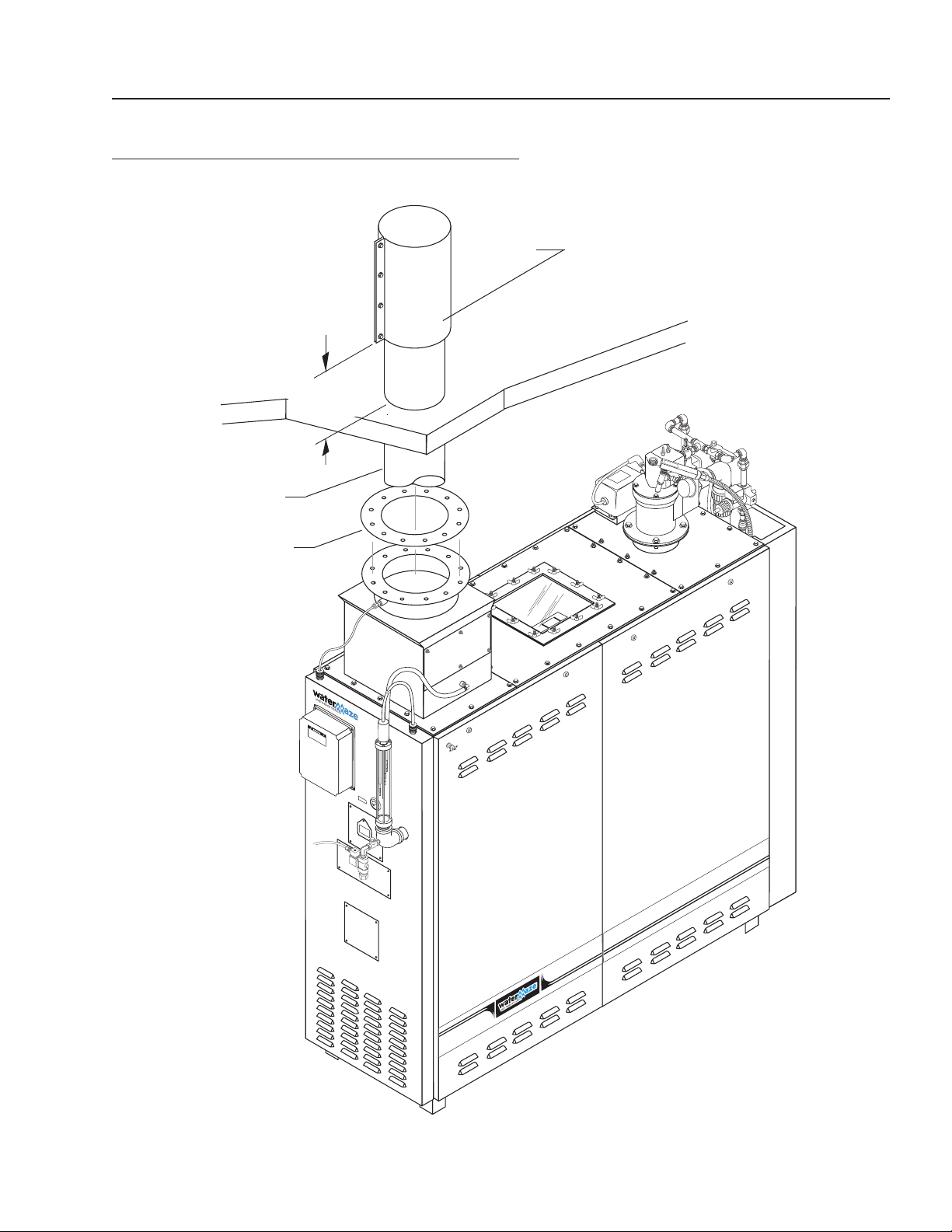
WATERMAZE SERIES OPERATOR’S MANUAL
EXHAUST STACKING CONFIGURATION
Flue Raincap
Roof
2'
Minimum
10" Flue
Exhaust
Pipe
13
Stack
Flange
Figure 4
WB • 8.913-984.0-L
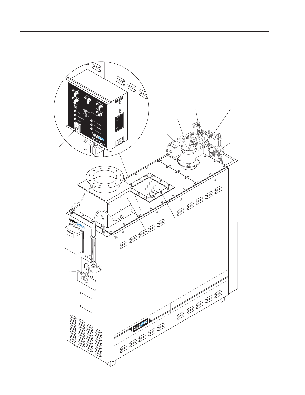
WATERMAZE SERIES OPERATOR’S MANUAL
14
WB-50
FRONT VIEW
Electrical
Box
Spark Plug
Main Gas Valve
Adjuster
Soft Start Gas
Valve Adjuster
(WB-50)
Burner Cycle
Level Controls
NEMA Box
Flame
View
Port
Timer
3 Point Level
Control Rods
Transformer
Demister
Screens
Soft Start
Solenoid
(WB-50)
Glass View
Port
Photohelic
Gauge
(Option)
Auto Flush
89139840-27
Figure 5
WB • 8.913-984.0-L

WATERMAZE SERIES OPERATOR’S MANUAL
89139840-26
15
WB-120A
FRONT VIEW
Burner
Cycle
Timer
Electrical
Box
Glass
View
Port
Transformer
Main Gas Valve
Adjuster Burner 1
Soft Start Gas
Valve Adjuster
Burner 1
Soft Start Solenoid
Burner 1
UV Scanner
Burner 2
Level Controls
NEMA Box
Flame View
Port
Demister
Screens
Auto Flush
Glass View
Port
3 Point Level
Control Rods
Figure 6
WB • 8.913-984.0-L
WATERMAZE SERIES OPERATOR’S MANUAL
89139840-24
89139840-25
16
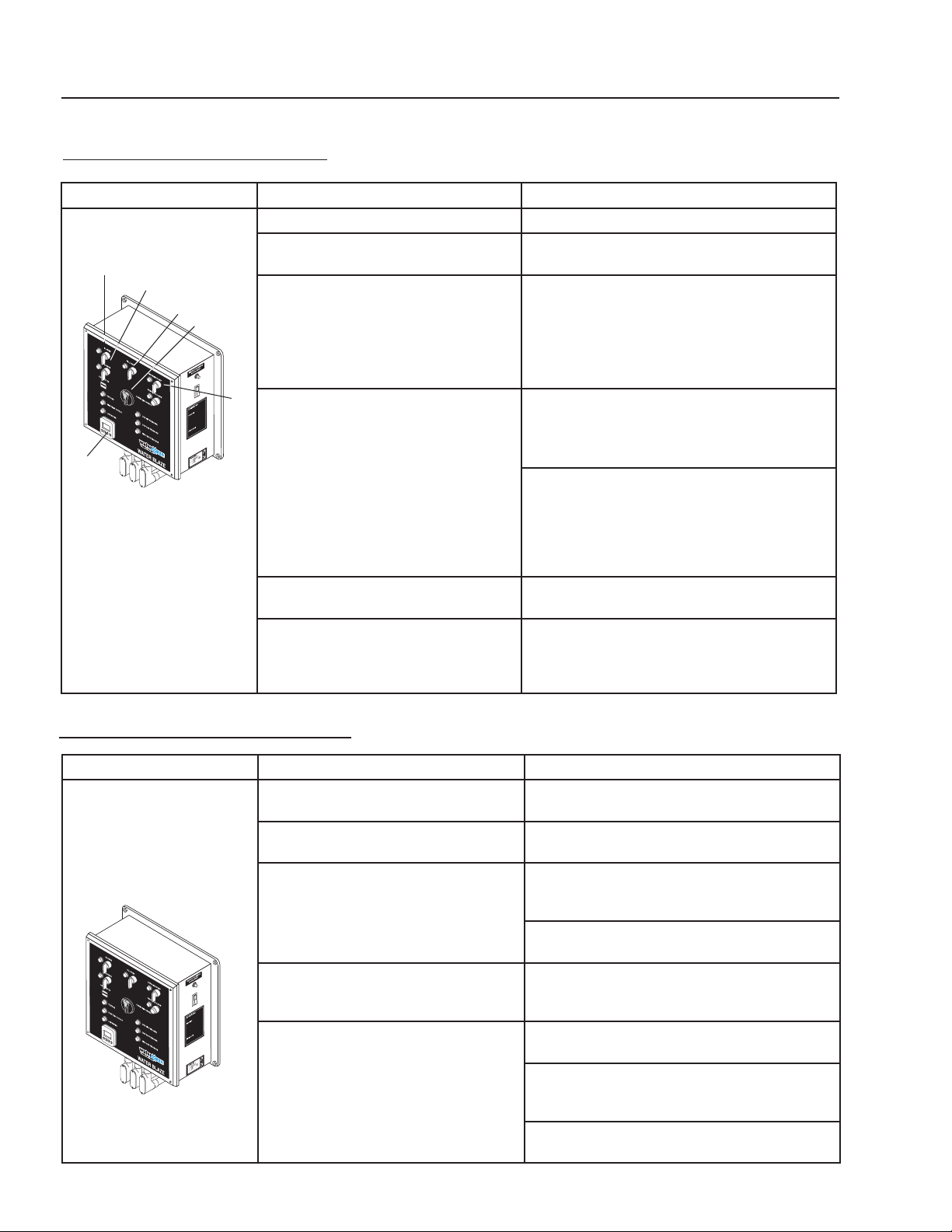
START-UP PROCEDURES
PANEL PROCEDURE RESULT
Turn on the main disconnect switch #1. Timer (LED screen) lights up.
Press F1/RST (reset button)
3
4
5
1
#2 on cycle timer.
Turn on the blower switch #3 to
desired position (manual or auto-matic).
“Manual” will bypass the liquid level float
in the customer's holding tank. “Automatic” will allow the float to control the
on/off operation of the blower.
6
Turn on the burner switch #4. The interlocks are checked and a green light will
2
Turn on the pump switch #5. As water is evaporated, the wastewater
Turn defoamer switch #6 to auto mode. Anti-foam will be added when fill pump is on.
Powers up the timer (LED screen).
Voltage light comes on.
Blower light turns on. Water
level in the sight tube will rise
as the water is evacuated
from the sparger tube.
WATER MAZE
be seen on the Veri-Flame. If there is a red light
on the Veri-Flame, there is a problem with one of
the interlocks that must be corrected.
After the interlocks are proven, the blower
will purge the sparger tube for 15 seconds,
then the burner will ignite. If the burner does
not ignite within eight seconds, the “UV scanner”
will shut the system down. At full burner
ignition, burner light turns on.
pump will automatically refill the tank.
If more defoamer is needed, turn the feed
adjustment (See page 48, figure 16) clockwise
to increase the speed of defoamer pump.
SHUT DOWN PROCEDURES
PANEL PROCEDURE RESULT
(To locate individual items,
please see above.)
Turn defoamer switch
#6 to middle off position.
Turn the pump
switch #5 off.
Turn the burner
switch #4 off.
Turn the blower
switch #3 off.
Turn the main
disconnect switch #1 off.
The defoamer
light goes out.
The pump light goes out. The waste stream
pump shuts down and the solenoid valve closes.
The burner light goes out. The burner shuts
down. The gas solenoid closes and the power
is cut to the transformer preventing a spark.
After turning the burner off, let the blower
run for at least one minute before turning it off.
The blower light goes out. At this point, the
blower shuts down and water from the tank
enters into the sparger tube.
The voltage light goes out. All power to the
evaporator is disconnected except to timer.
The water in the evaporator is still HOT at this
point. Allow the water to cool before any
maintenance is done, i.e., sludge removal.
If the evaporator is to be left off overnight or
longer, shut off the gas supply to the evaporator.
WB • 8.913-984.0-L

WATERMAZE SERIES OPERATOR’S MANUAL
17
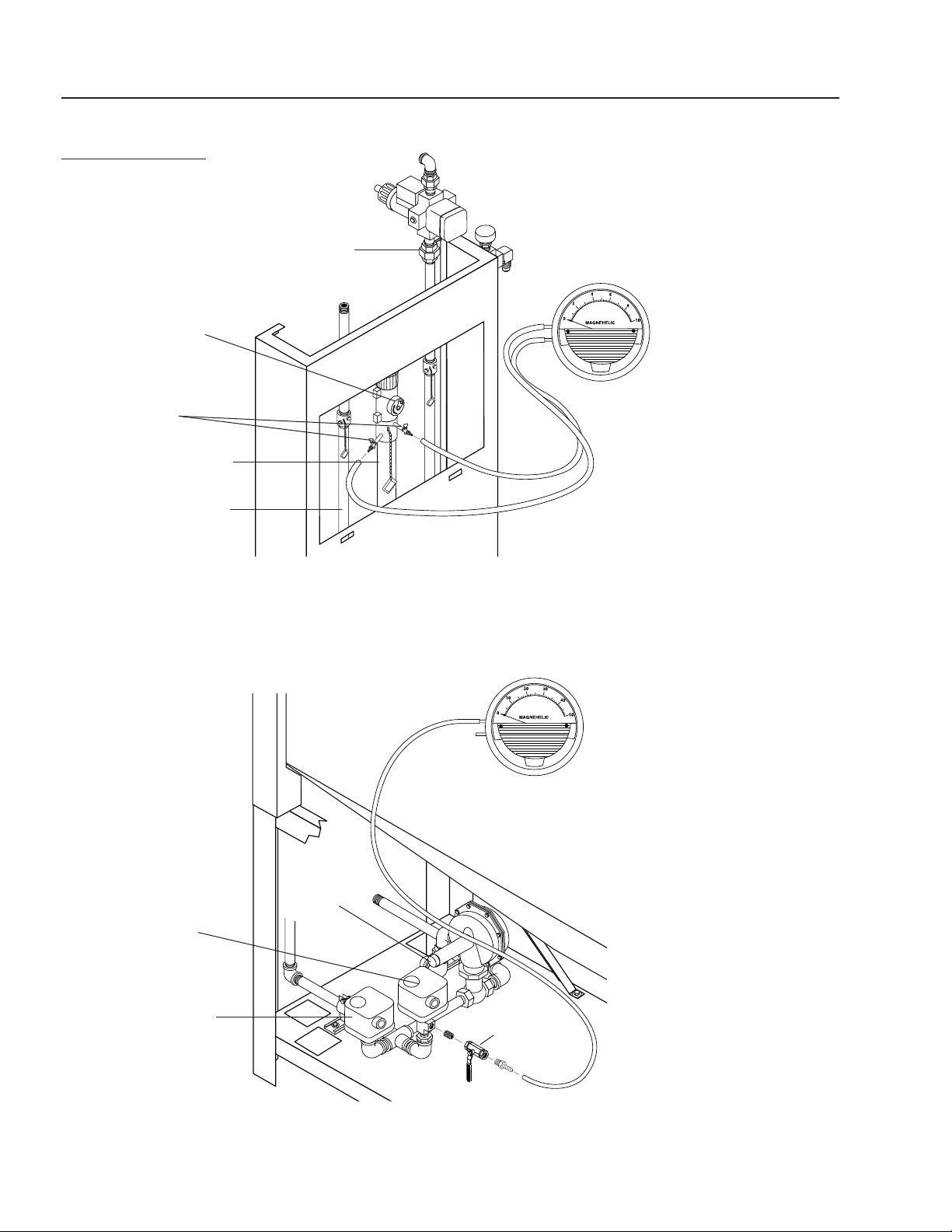
SETTING THE BURNER
The quickest and easiest way to adjust the air and gas
differential to the appropriate settings listed below is to
purchase the WATER MAZE set up kit (#7-8200). Refer
to figure 7 for locations on setting the burner. Shut main
gas valve off. With 7/16" wrench remove brass plugs
from all metering orifices on back side of machine. Install
brass valves included in set up kit into each position
and close. Turn gas main valve back on. To set static
pressure, use 0 - 50 manometer on (D or E). To adjust
setting to desired 45 wci, remove cap on gas regulator
(F) and turn inside adjustment screw clockwise for higher
pressure, counterclockwise for lower pressure. Replace
cap. Start machine by turning the blower switch to the
“auto” position and burner switch to the “on” position.
Once the burner lights, use the 0 - 10 manometer to set
the air differential at (B). Note: lower port is high pressure and upper port is low pressure. With hoses in position, open brass valves. Set air differential as per chart
below. Note: needle will shake; pinch both hoses lightly
together to read number. Adjust by opening or closing
main air butterfly and secondary air butterfly (located
on left side of burner, up top). Close brass valves. Set
the gas differential the same way as the air. Note: read
chart for proper gas used. Attach 0 - 10 manometer at
(C) and set as per chart. The adjustment valve is located
to the right of the burner up top. Remove the brass cap
and adjust with a standard screwdriver. You will have to
set one burner at a time on a WB-120. Once adjusted,
shut off burner and blower. Shut off main gas line. Now
remove the brass valves used with the manometers and
replace plugs into the air and gas orifices. Turn the main
gas back on and follow the procedures for start up. Your
evaporator is now in service.
SOFT START IGNITION
To provide a smooth ignition and meet all gas train
standards, the WB-50 and WB-120 come standard with
the soft start ignition system. Before trial of ignition the
Veri-Flame will make sure the top gas solenoid is closed
(proof of closure). Once closed, the Veri-Flame will try for
a pilot flame. After approximately 8 seconds, the proof
of closure solenoid will close and allow the main gas
solenoid to open slowly.
Soft start settings: The gas metering orifice SBO-A-1
(A) for the soft start needs to be set on 7 wci for the gas
differential. Follow (Setting The Burner) instructions for
setting the soft start gas differential.
NATURAL GAS:
UNIT GPH METERING
WB-50A
WB-120A
60 SBO-D-7 6.5 SBO-677 8
120 SBO-D-7 6.5 SBO-677 8
LIQUID PROPANE GAS:
UNIT GPH METERING
WB-50A
WB-120A
60 SBO-C-3 6 SBO-677 9
120 SBO-C-3 6 SBO-677 9
ORIFICE
ORIFICE
GAS DIFFERENTIAL METERING
ORIFICE
GAS
DIFFERENTIAL
METERING
ORIFICE
AIR DIFFERENTIAL
AIR
DIFFERENTIAL
WB • 8.913-984.0-L
WATERMAZE SERIES OPERATOR’S MANUAL
18
WATER MAZE
BURNER ADJUSTMENT
Main Gas Pipe
(All Models)
Main Air
Valve
Test Valves
Main Air Pipe
(All Models)
High
Air/Gas
Differential
Low
Soft Start
Gas Pipe
WB-50/120 Models
High
Low
High Switch
Low
Switch
Static Gas
Gas
Regulator
Cap
Static Gas
Check Port
WB-50/120 Models
Figure 7
WB • 8.913-984.0-L
 Loading...