

Water Maze CLP-5024, CLP Series, CLP-7034 Operator's Manual
CLP
OPERATOR’S MANUAL
■ CLP-5024 ■ CLP-7034
89139700-14
For technical assistance or the WATER MAZE dealer nearest you, visit our website at
www.wmaze.com
WARNING:
This product and accessories may contain a chemical known to the State of
California to cause cancer and birth defects or other reproductive harm.
For more information about this regulation: www.P65Warnings.ca.gov
8.913-970.0 - L02/12/19


Introduction ..................................................................................................... 5
Unpacking ....................................................................................................... 5
Important Safety Information .......................................................................6-7
Installation Instructions .............................................................................. 7, 8
Check List Before Starting ..............................................................................8
Installation View .........................................................................................9-10
Start-up ......................................................................................................... 11
Operation CLP-5024/7034 .......................................................................11-12
Pressure Switch and Pressure Tank Operation ............................................ 13
Programming Instructions ........................................................................14-15
Valve Location & Function .......................................................................16-17
Operation Views .......................................................................................18-19
Water Panel Installation ................................................................................ 20
Standard ORP/pH Sensors ...........................................................................21
Sensor Maintenance ..................................................................................... 22
CONTENTS
Troubleshooting - Standard ORP/pH Sensors .............................................. 23
VSP20 Metering Pump ................................................................................. 24
General Maintenance & Service ...................................................................25
Ozone Generator .....................................................................................25-26
Ozone Generator Breakdown Exploded View & Parts List ......................27-28
Chemical Maintenance Program ..................................................................29
Daily Chemical Maintenance ........................................................................ 30
Centrifugal Pump Operation & Maintenance ................................................ 31
CLP-5024 Main Tank Plumbing Exploded View & Parts List ...................32-33
CLP-5024 & 7034 Electrical Box Exploded View & Parts List .................34-36
CLP-5024 Storage Tank Exploded View & Parts List .................................... 37
CLP-5024 Pumps Plumbing Exploded View & Parts List ........................38-39
CLP-5024 Plumbing Exploded View and Parts List .................................40-41
CLP-5024 Filter Plumbing Exploded View and Parts List ........................42-43
CLP-5024/7034 Water Panel Breakdown Exploded View & Parts List ....44-45
CLP-7034 Holding Tank Assemblies Exploded View & Parts List ............46-47
CLP-7034 Tank Drain & Oil Skimmer Exploded View & Parts List ...........48-49
CLP-7034 Main Tank Exploded View & Parts List ...................................50-51
CLP-7034 Transfer Pump Exploded View & Parts List .............................52-53
8.913-970.0 - L • WATERMAZE CLP 5024/7034
3

CONTENTS
CLP-7034 Carbon/Multi Media Filter Plumbing Expl. View & Parts List ...54-55
CLP-7034 Flow Meter Plumbing Exploded View & Parts List ..................56-57
CLP-7034 Ozone Pump Exploded View & Parts List ...............................58-59
CLP-7034 Filter Pump Exploded View & Parts List .................................60-61
CLP-7034 Surge Tank/Main Drain Exploded View & Parts List ...............62-63
CLP-7034 Manifold Exploded View & Parts List ......................................64-65
Metering Pump Exploded View & Parts List .................................................66
Transfer Pump Exploded View & Parts List ................................................... 67
Filter & Transfer Pumps Exploded View Parts List ...................................68-69
Ozone Pump Exploded View & Parts List .....................................................70
Ozone Pump Exploded View & Parts List .....................................................71
Submersible Sump Pumps Specifi cations .................................................... 72
Multi-Media/Carbasorb Filter Exploded View & Parts List ............................73
Carbasorb Filter Exploded View & Parts List ................................................ 74
Multi-Media Filter Exploded View & Parts List ..............................................75
6 Position Valve Exploded View & Parts List ................................................. 76
2" Multi-Port Valve Exploded View & Parts List .............................................77
Troubleshooting .......................................................................................78-83
Consumable Parts ........................................................................................ 84
CLP-7034 Maintenance Schedule ................................................................85
Warranty .......................................................................................................86
Model Number ____________________________________
Serial Number _____________________________________
Date of Purchase __________________________________
The model and serial numbers will be found on a decal attached
to the machine. You should record both serial number and date of
purchase and keep in a safe place for future reference.
4
8.913-970.0 - L • WATERMAZE CLP 5024/7034

INTRODUCTION & SAFETY INFORMATION
INTRODUCTION
Your owner’s manual has been prepared to provide you
with a simple and understandable guide for equipment
operation and maintenance, based on the latest product information available at the time of printing. To keep
your machine in top running condition follow the specifi c
maintenance and troubleshooting procedures given in
this manual. When ordering parts please specify model
and serial number.
NOTE: WATER MAZE reserves the right to make
changes at anytime without incurring any obligations.
Owner/User Responsibility:
The owner and/or user must have an understanding
of the manufacturer’s operating instructions and
warnings before using this WATER MAZE machine.
Warning information should be emphasized and
understood. If the operator is not fl uent in English, the
manufacturer’s instructions and warnings shall be read
to and discussed with the operator in the operator’s
native language by the purchaser/owner, making sure
that the operator comprehends its contents.
The owner and/or user must study and maintain the
manufacturers’ instructions for future reference.
WATER TREATMENT SYSTEM
OPERATOR’S MANUAL
SAVE THESE INSTRUCTIONS
This manual should be considered a permanent part
of the machine and should remain with it if machine
is resold.
When ordering parts, please specify model and
serial number. Use only identical replacement parts.
This machine is to be used only by trained operators.
UNPACKING
1. CLP Machine Assembly
2. Sludge Tub
3. Sludge Tub Bag Support
4. Accessory Box
6. Operator’s Manual
NOTE: Any damage to machine or components for
claims against the freight lines.
8.913-970.0 - L • WATERMAZE CLP 5024/7034
5
INTRODUCTION & SAFETY INFORMATION
WARNING
CAUTION
IMPORTANT
SAFETY
INFORMATION
CAUTION: To reduce the risk of
READ OPERATOR’S
MANUAL THOROUGHLY
PRIOR TO USE.
injury, read operating instructions carefully before
using.
WARNING
KEEP WATER SPRAY
OPERATOR’S MANUAL WATER TREATMENT SYSTEM
AWAY FROM
ELECTRICAL WIRING.
corder à la source d'alimentation.
WARNING
RISK OF EXPLOSION:
DO NOT SPRAY
FLAMMABLE LIQUIDS.
Code national de l'électricité et les codes locaux
pour tous les câblages.
WARNING: Follow the wiring instructions in this
manual when connecting the system to the power
lines.
AVERTISSEMENT: Suivre les instructions de câblage
dans le présent manuel au moment de
raccorder le système aux lignes de transport
d'électricité.
WARNING: All wiring must be performed by a qualifi ed electrician.
AVERTISSEMENT: Tout le câblage doit être effectué
par un électricien qualifi é.
2. Know the system application, limitations, and potential hazards.
WARNING: Do not use to pump
concentrations of flammable
6
injury, read operating instructions
carefully before using.
ATTENTION: To reduce the risk of
1. Read the owner’s manual thoroughly. Failure to follow the instructions will cause a malfunction of the
machine and result in death, serious
injury and/or property damage.
WARNING: Ground system before
connecting to the power supply.
AVERTISSEMENT: Mettre le système à la masse avant de le rac-
WARNING: Wire the system for
correct voltage. See “Electrical”
section of this manual and motor
nameplate.
WARNING: Meet the National
Electrical Code and local codes
for all wiring.
AVERTISSEMENT: Respecter le
8.913-970.0 - L • WATERMAZE CLP 5024/7034
or explosive fl uids such as gasoline, fuel oil, kerosene, etc. Do not use in explosive atmospheres.
Pumps should only be used with liquids compatible
with pump component materials. Failure to follow
this warning can result in personal injury and/or
property damage.
AVERTISSEMENT: Les pompes devraient être utilisées uniquement avec des liquides compatibles
avec les matériaux des composants des pompes. Le
non-respect des précautions peut mener à des lésions corporelles et/ou des dommages à la propriété.
3. WARNING: Risk of electric shock.
AVERTISSEMENT: Risque de choc électrique
All wiring should be performed by a qualified
electrician.
4. Never make adjustments on the machine while it
is in operation, except for those prescribed in this
manual.
5. The main power must be brought from the circuit
breaker and wired into the electrical box on the CLP.
This line must be run through conduit to protect it
from damage. A power disconnect should be located
next to the machine for maintenance purposes.
6. Before servicing the machine, refer to all the MSDS’s
on the material identifi ed in the wastestream. You
must comply with all warnings and wear all protective clothing as stated on the MSDS’s.
7. Protect all electrical cords from sharp objects, hot
surfaces, oil, sunlight, and chemicals. Avoid kinking
the cords. Replace or repair damaged or worn cords
immediately. All wiring should be run through conduit.
8. Inlet water temperature must not exceed 85°F.
9. Disconnect the power before servicing this machine.
If the power disconnect is out of sight, lock it in
the open position and tag it to prevent unexpected
application of power.
10. The best insurance against an accident is precaution
and knowledge of the equipment.
11. WATER MAZE is not liable for modifi cations or use
of components not purchased from WATER MAZE.
12. Personal Safety:
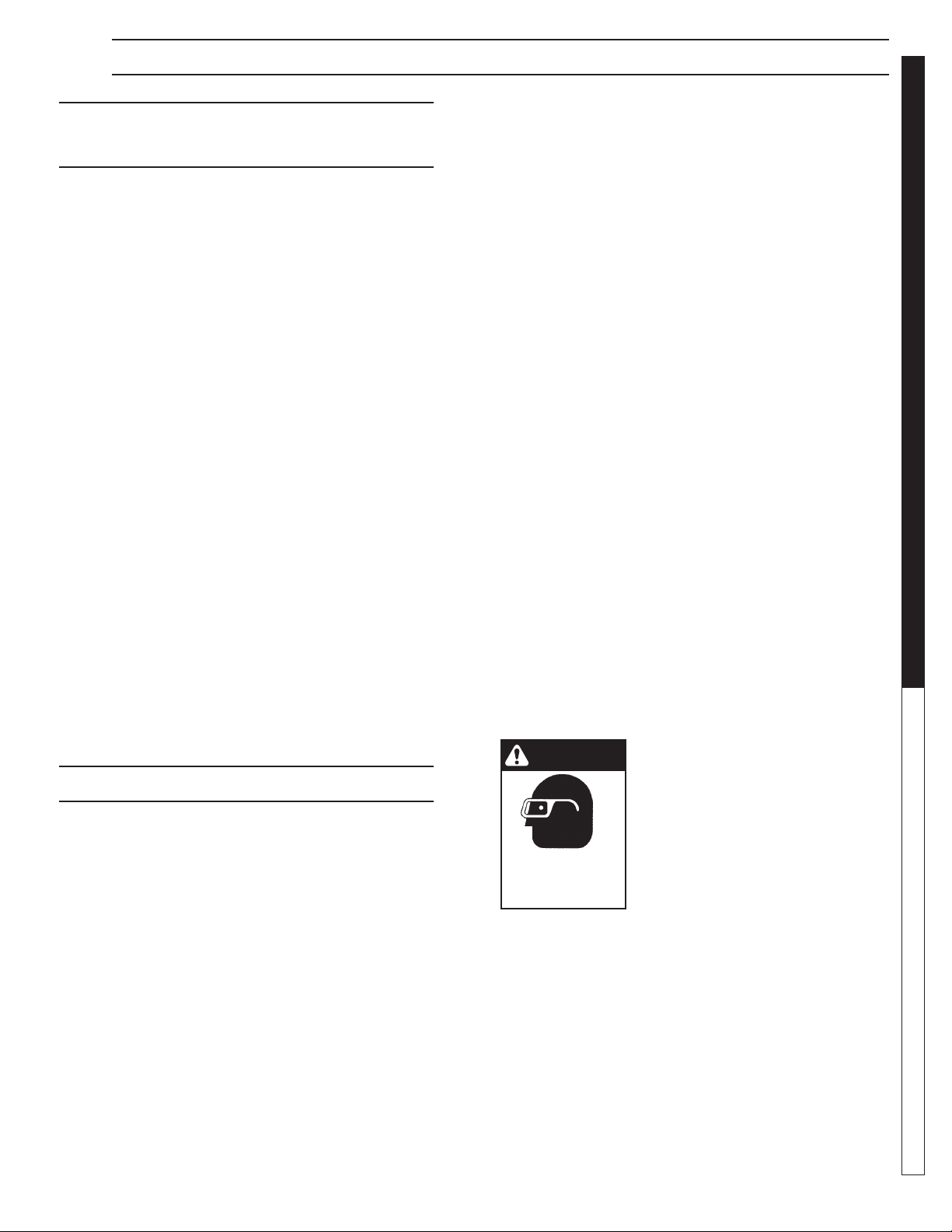
a. Wear safety glasses and other applicable
protective clothing at all times when working
on the CLP.
Refer to item #6 under Important Safety
Information.
b. Keep your work area clean, uncluttered and
properly lighted. Replace all unused tools and
equipment.

INSTALLATION INSTRUCTIONS
WATER TREATMENT SYSTEM
c. Keep visitors at a safe distance from work area.
d. Make the workshop safe with padlocks and
master switches.
13. Running the system without water will damage the
pumps and will void the warranty.
14. Release all pressure within the system before
servicing any component.
15. Drain all liquids from the component before
servicing.
16. Check hoses for weak or worn conditions before
each use, making certain that all connections are
secure.
17. Periodically inspect pump and system components.
Perform routine maintenance as required.
18. Do not touch an operating motor. Modern motors
are designed to operate at high temperatures.
19. Do not handle a pump or pump motor with wet hands,
when standing on a wet or damp surface, or in water.
20. The pump motors are equipped with an automatic
resetting thermal protector and may restart unexpectedly. Tripping is an indication of motor overloading as a result of operating the pumps at low heads
(low discharge restriction), excessively high or low
voltage, inadequate wiring, incorrect motor connections, or a defective motor or pump.
21. IMPORTANT NOTE: The sump pump is not a
trash pump and is subject to premature failure
unless sump pit baffl ing or additional protection is
provided.
22. Do not stand on the bracket that supports the
Electrical Box, Ozone Generator and the ORP/pH
Controller or on tanks 1 or 2. During installation and
maintenance obtain an OSHA approved ladder.
23. Keep machine from freezing.
24. Do not spray water directly at machine.
INSTALLATION INSTRUCTIONS
1. Because of the nature of the equipment, it is recommended these machines be installed indoors.
2. Locate the CLP on a containment pad to prevent
contamination.
3. Level machine by using shims that will provide ample
support and will not corrode or deteriorate over time.
4. Have a qualifi ed electrician connect the proper
power supply to the electrical control box. It is recommended that a ground fault circuit interrupter be
installed in the circuit breaker for the CLP.
NOTE: An electrician needs to locate where the
power supply will enter the electrical box and punch
a hole.
5. Install Orp/pH probes into cone bottom tank. Remove
cap and immerse probes into water. Don't let probes
dry. Save cap for future need.
6. Install the angle face dump valve on bottom of cone
bottom tank. Run air hose from angle face dump
valve to air valve assembly. Follow electrical wiring
diagram for air switch wires.
7. Plumb oil decanter barrel.
8. Run ORP/pH pump hoses from pumps to injectors.
9. Run air from air compressor to machine. Use at least
a 3 CFM air compressor with 60-100 psi.
10. Drill holes for 2" bulkheads and install bulkheads.
Connect the sludge tub assembly by placing the
sludge bag support into the sludge tub. Attach the
sludge bag onto the sludge inlet fi tting using the
screw clamp provided.
11. Attach the 2" fl ex hose to the sludge tub by screwing
the hose barbs into the bulkhead connectors, then
attach the 2" fl ex hose to the hose barb using a hose
clamp. The return line should gravity return to the
catch basin. The 2" inlet fl ex hose should connect
between the cone tank discharge valve and the
sludge bag inlet connector.
12. Build the inlet plumbing from the sump pump discharge port (min. 1-1/2" pipe) to the CLP 1-1/2" inlet
line. If the pipe is to be under the concrete, use 2"
pipe. Lower the sump pump into the sump pit.
13. Position the sump pump in the bottom of sump pit.
a. Elevate on a stand or cinder blocks, 6" off the
pit fl oor, to keep pump from sucking in rocks
or other heavy material that may plug pump or
plumbing.
b. Position the pump away from incoming water to
help prevent cavitation.
OPERATOR’S MANUAL
8.913-970.0 - L • WATERMAZE CLP 5024/7034
7

INSTALLATION INSTRUCTIONS
c. Tie a rope or chain to the pump handle and
bring out of the top of the pit for ease of pump
removal. Do not lift pump by power cords or
plumbing. Have a union installed on plumbing at
the top of the pit. Position union so it can easily
be reached and opened for pump removal.
14. The High Level Control Float FS1 (black, normally
open) is the upper fl oat which controls the upper
limits of the sump. It prevents the sump from fl ooding by opening SV1, the rain water solenoid valve.
Float tether length must be a minimum of 2" long.
Position the upper most point of fl oat a few inches
below top of pit. The Fresh Water Make-up Float FS2
(grey, normally closed) controls the lower limits of
the sump. It prevents the sump from running dry by
opening SV2, the fresh water solenoid valve. Turn-on
point for the Fresh Water Make-up Float must be at
least 8" above the suction inlet of sump pump. The
OPERATOR’S MANUAL WATER TREATMENT SYSTEM
further the water must travel before reaching the
sump, the higher the fl oat must be placed above the
suction intake. On three phase units, a third fl oat is
needed to protect the sump pump from the possibility
of running dry. Position the Low Water Protector Float
#7 (grey, normally closed) 6" above the suction inlet
of sump pump. Single phase sump pumps have a
fl oat built into them.
Floats must travel their complete arc without:
Water going over the top of the pit.
Touching sidewalls or bottom.
The pit running out of water.
Interfering with electrical wiring, plumbing, bottom
or sidewalls of sump, or any object. Attach the
fl oats to the PVC line on the sump pump.
Check to assure the fl oats can operate freely.
(See Installation View.)
15. Run the electrical cords from the sump pump and
fl oats to the electrical junction boxes near the inlet
line and attach wires. If the sump pump and fl oats
are located farther then 20 feet from the electrical
junction boxes, then have an electrician install water
tight junction boxes with conduit and proper sized
wire to extend the electrical connections.
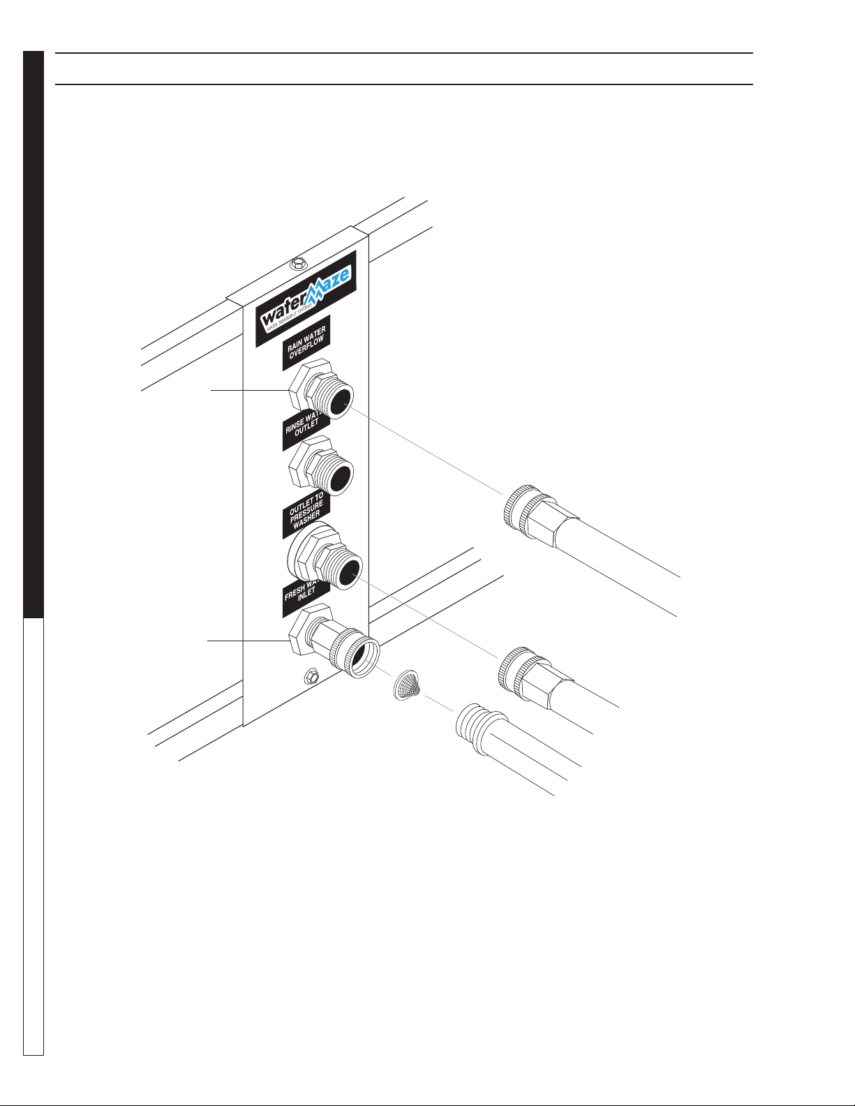
16. Connect the fresh water line (3/4" GHM garden hose
not provided) to the “Fresh Water Inlet” port on the
water panel (see Water Panel Illustration).
17. Connect the “Outlet to Pressure Washers” to your
pressure washer by using a 5/8" garden hose (not
provided). Valve #7 behind the water panel should
remain closed until start-up. You may need a 1" line to
obtain a higher fl ow. If you are going a great distance
or using a lot of elbows, you may not get full fl ow.
18. Connect the “Rain Water Overfl ow” to the sewer or
storage (line not provided). Valve #8 behind the water
panel should remain halfway open.
CAUTION: Discharge Permits are required and
must be obtained before any treated water is
discharged.
ATTENTION: Des permis de déversement sont
requis et doivent être obtenus avant de procéder
au déchargement de toute eau traitée.
19. Connect a hose to “Rinse Water” outlet if it is to be
used. Make sure valve #6 behind the water panel
stays closed until rinse water is needed (hose not
provided).
NOTE: The use of rinse water in a closed loop
system will overfi ll the system and will lead to an
overfl ow situation causing the rainwater overfl ow
valve to open.
20. Run the "Return/Backwash" line back to the collection pit or fi rst pit where the water will be collected.
This is very important so that there is no stagnant
water when recycling and also to give more setting for the backwash water. If not done properly, it
could void warranty. Run at least a 2" line if above
ground and 3" if below ground. The sludge tub and
oil decanter barrel are plumbed together and run to
the return line. Any back pressure could overfl ow
the sludge tub and/or oil decanter barrel. A separate
return line for the sludge tub and oil decanter barrel
may be needed , the sludge tub can be elevated or
a check valve can be installed.
CHECK LIST
BEFORE STARTING:
Yes No
1. Is inlet line connected from
the sump pump to the inlet
of the machine? ___ ___
2. Is the voltage correct? ___ ___
3. Is the return line connected? ___ ___
4. Is the Fresh Water Make-up
hose connected? ___ ___
5. Is the Outlet to Pressure
Washer hose connected. ___ ___
6. Is the Rainwater Overfl ow
connected? ___ ___
START-UP:
8
8.913-970.0 - L • WATERMAZE CLP 5024/7034
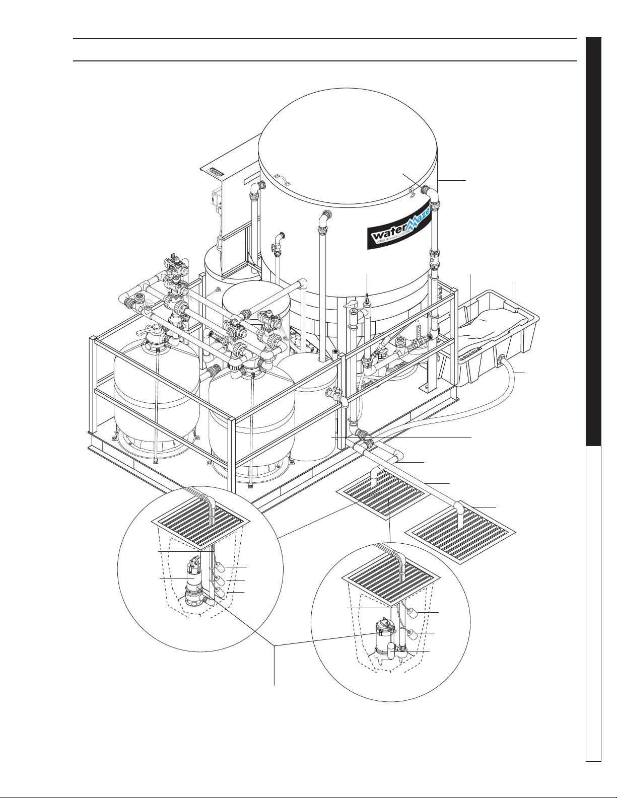
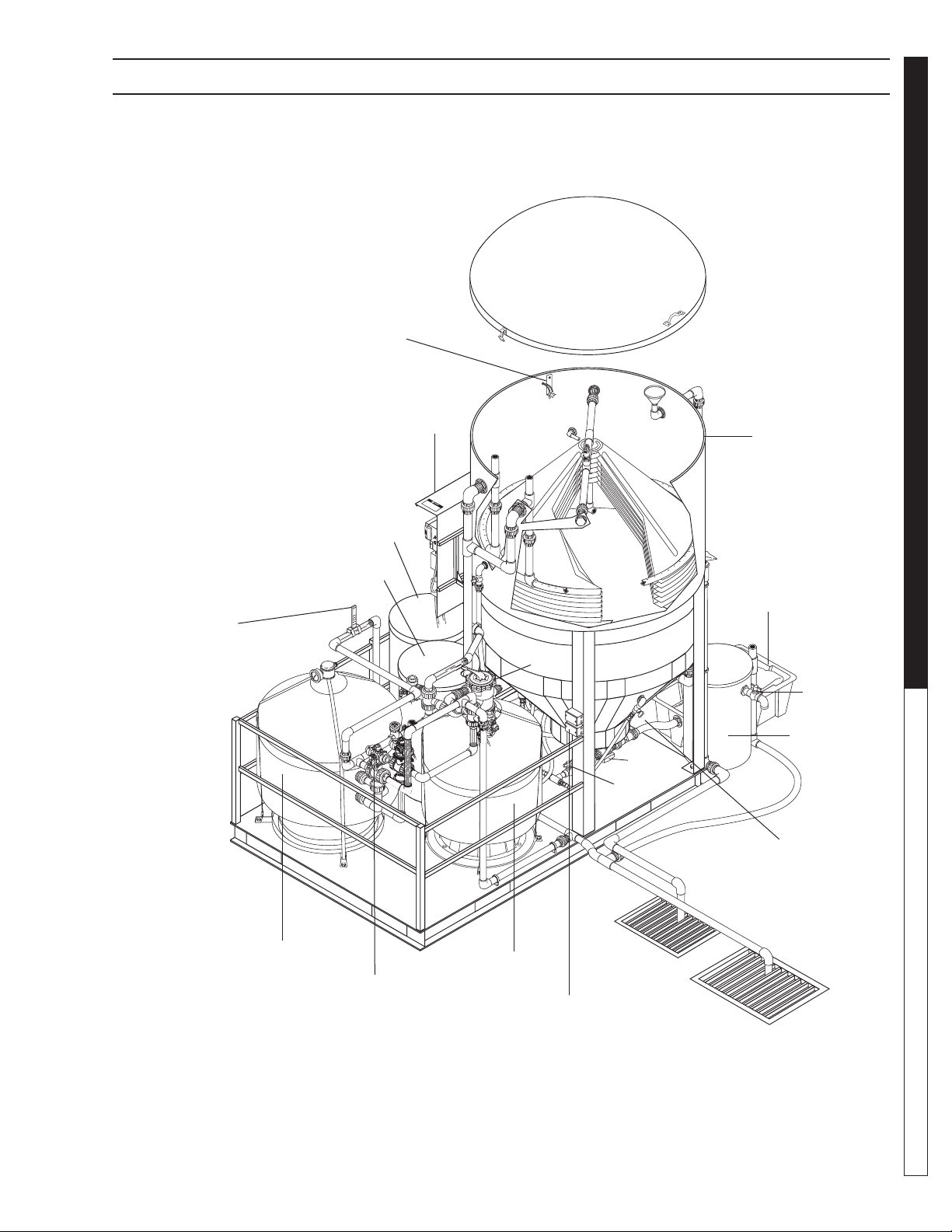
CLP-5024 INSTALLATION VIEW
Inlet
pH Injector
Cone
Bottom Tank
Bag
Support
Sludge
Tub
WATER TREATMENT SYSTEM
OPERATOR’S MANUAL
Inlet
Line
Sump
Pump
Sump Pump
Installation
(3 Phase)
Sump
Pit
FS1
FS2
FS7
Inlet
Line
2" Flex
Hose
Oil Decanter
Barrel
Inlet
Line
Return
Backwash Line
Catch
Basin
Sump
Pit
FS1
FS2
Sump
Pump
Sump Pump
Sump Pump Not Supplied
with Machine. See
Specifi cation on Page 70.
8.913-970.0 - L • WATERMAZE CLP 5024/7034
Installation
89139700-3
9

CLP-7034 INSTALLATION VIEW
Cone Bottom Tank
Flow Meter
Inlet
Sludge Tub
OPERATOR’S MANUAL WATER TREATMENT SYSTEM
3 Way
Ball Valve
Assembly
Inlet
Line
Sump
Pump
Sump Pit
Sump
Pump
Installation
FS1
FS2
Inlet
Line
Sump Pit
Installation
(3 Phase)
Sump
Pump
FS1
Oil
Decanter
Barrel
2" Flex Hose
Inlet Line
Return/Backwash
Line
Catch Basin
10
Sump Pump Not Supplied
with Machine. See
Specifi cation on Page 70.
8.913-970.0 - L • WATERMAZE CLP 5024/7034
FS2
FS7
89139700-21
Sump
Pump

START-UP INSTRUCTIONS
WATER TREATMENT SYSTEM
• Make sure that the CLP is level.
• Turn on the Fresh Water Makeup hose.
• After checking for proper power supply voltage,
turn on the circuit breaker to the CLP Machine.
NOTE: Make sure all switches are turned ”OFF”.
• Fill the sump pit with water, and check that the water
level does not drop, which would indicate the pit is
not sealed.
• Turn the sump pump switch to the ON position. The
sump pump lamp will illuminate if sump pump is
operating. (NOTE: the pump has an internally operated fl oat for low water on single phase only. The
sump pump should fi ll the cone bottom tank with
water. FS3 in tank 1 will shut off the sump in the up
position).
• Adjust the fl ow of water into the CLP using valve
#1 by reading the indicator marks on the inlet fl ow
meter. Set fl ow 2-4 GPM above demand.
• The ozone genertor is programmed to run from 11:00
p.m. to 4:00 a.m. every night. If more ozone is needed
during the day time hours, program Ozone 2 and
Ozone 3 on the PLC to the desired times needed.
• Turn the fi lter pump switch to the ON position. Tank
#2 should fi ll and FS5 will turn off the fi lter pump
when in the up position. The fi lter pump lamp will
illuminate when pump is in operation.
• Adjust valve #10 so that the fi lter fl ow meter has the
same or 2 GPM lower fl ow rate than the inlet GPM
fl ow rate.
• Turn the transfer pump switch to the ON position.
The pump should pressurize and shut off. NOTE:
When the pump is put into operation the pressure
switch may need to be adjusted. See inside cover
of pressure switch for adjustment instructions. The
2 HP pump is set at 20 PSI ON and 40 PSI OFF.
The transfer pump lamp will illuminate when pump
is operating.
• Turn the ozone pump switch to the ON position.
• Check to ensure the oil skimmer is adjusted properly.
Adjust if needed by screwing the funnel up or down,
or angling the pipe to allow a small amount of water
to free fl ow. If oil starts to build up on top of the cone
tank, adjust the skimmer to allow increased fl ow.
NOTE: Only adjust the oil skimmer when the sump
pump is running.
• Place the ORP/pH probes in the bracket inside the
CLP tank. Remove the liquid fi lled cap on the end of
the probes and place them in the bracket. Make sure
the tank is full of water and the probes are kept wet.
Run the connector through the hole in the tank wall
near the bracket and attach the connectors to the
controller. The connector with the white tag near it
is the ORP and is connected to the top stud on the
controller. The other is the pH and is connected to
the bottom stud on the controller.
• Look over entire machine for leaks. The machine
was hydrostatically tested at the factory but may
have been damaged in shipment.
• Program the AMC controller (CLP-7034).
• Turn the ozone generator ON/OFF switch ON.
• Set ozone generator for proper air fl ow.
• Turn ORP/pH controller switch ON.
• Turn ORP/pH feed pumps ON.
• Adjust valves per instructions (See Standard Orp/
pH Controller pages).
OPERATION: CLP-5024/7034
The CLP-5024/7034 are a fully automatic, self-contained
wash water recycling system suitable for treating wastewater generated from cleaning machinery and equipment. They are designed to separate free oil/greases
and dirt.
At the heart of the automated system is an automatic
maintenance controller (AMC). The AMC provides the
benefi ts of reliability and versatility to control numerous
functions. The AMC controls pump operations, machine
mode light display, fi lter status, backwash requirements,
recirculation, ozone injection, and sludge dumping.
Filter Mode
In a typical operation, wastewater is gravity fed from a
wash pad catch basin to a sump pit (preventing large
solids from entering the sump pump). Water resides in
the sump pump pit until Tank #1 requires water. On Tank
#1's demand, wastewater is pumped into the cone bottom tank. In the cone bottom tank the following occurs:
• Wastewater exits the tank by passing through
a series of corrugated coalescing cones. These
cones slow the fl ow of water (velocity drop) allowing the separation and settling of solids. Solids
settle to the bottom of the tank and are later automatically removed (see automatic sludge dump).
The coalescing cones oil attracting properties,
combined with the 55° incline angle, maximizes
free oil/water separation. Free oils are skimmed
from the surface and discharged to a 26 gallon
oil decanter for further separation.
• To control odor and kill bacteria, an ozone pump
recirculates ozonated water through the upper
section of the cone bottom tank.
OPERATOR’S MANUAL
8.913-970.0 - L • WATERMAZE CLP 5024/7034
11

OPERATING INSTRUCTIONS
Water is gravity fed from the 600 gallon tank to Tank #1
and remains there until Tank #2 requires water. When
water is consumed from Tank #2 (by pressure washer,
recirculation or sewer discharge) the fi lter pump circulates water from Tank #1 through the fi lters to Tank #2.
Flow rates through the fi lters can be adjusted up to 30
gallons per minute (GPM). For best results the fl ow rate
should be set to the lowest GPM that still allows the
entire system to operate correctly (the lower fl ow rate
increases wastewater/fi lter contact time and reduces the
fi lters solids loading).
Water remains in Tank #2 until it is either discharged
to the sewer (check your local regulations for limits in
your area), reused by the pressure washer or used for
recirculation of the pits and fi lters (see recirculation
mode). In the event an excess amount of water enters
the system (through rinse water or rain water) water is
automatically discharged from Tank #2 through the rain
water overfl ow solenoid valve to either the sewer or to
a holding tank. If the system's water level becomes too
low (i.e. evaporation, vehicle carry off), a fresh water
OPERATOR’S MANUAL WATER TREATMENT SYSTEM
make-up solenoid valve feeds fresh water to Tank #2
until proper levels are maintained.
Filters
To ensure optimum filter performance and life, the
multi-media and carbon fi lters must periodically be
backwashed (see automatic backwash mode).
• The multi-media fi lter consists of a blend of sand,
garnet, gravel and anthracite. The media blend is
effi cient in screening out solids to 25-30 microns.
During the recirculation mode, the constant fl ow
through the media fi lter provides a fi nal polish to
the water.
• The carbon fi lter consists of degassed, virgin activated carbon. Carbon removes, through absorption, pesticides, solvents, benzene, diesel fuels,
acetone and other hydrocarbons as well as low
levels of heavy metals.
Automatic Backwash Mode
Backwashing the media fi lters is required to rejuvenate
the fi lter media. Backwashing removes collected materials and disperses the media to eliminate any channeling.
During normal operation of the CLP-5024/7034, the
multi-media fi lter, carbon fi lter or both may become
impacted with fi ltered solids, resulting in pressure head
loss through the fi lters and in poor overall performance.
The CLP-5024/7034 will backwash everyday if it needs
to or not. The multi-media will start backwashing at
midnight for 30 minutes. The CLP will then recover the
water level in Tank #1 and then backwash the carbon
fi lter. The operator cannot use the pressure washer at
that time, so it is important that the program imitates
your schedule. If it doesn't, call factory for assistance in
reprogramming your controller.
To backwash, the affected fi lter is isolated and the fl ow is
reversed via air actuated three way valves. A slip stream
solenoid is activated to allow proper water fl ow (30 GPM
for multi-media valve 20, 15-20 GPM for carbon valve
21) and water is pumped from Tank #1 through the fi lter
by the fi lter pump. This process continues for 30 minutes
and the resulting backwash outfl ow is returned to the
wash pad catch basin.
Once backwashing of the fi rst fi lter is completed the
second fi lter will then be backwashed. At no time will
both fi lters be backwashed at the same time.
Recirculation Mode
The purpose for recirculating the water through the pit
system and the fi lters is to minimize odor, kill bacteria
and provide high quality polished water.
Once each day the CLP will enter a recirculation mode.
This mode consists of two separate stages.
Stage 1: The transfer pump sends water from Tank #2
through the return line to the wash pad catch
basin. To prevent odor and kill bacteria, the
return water is ozonated via a mazzi injector.
Stage 2: Water is recirculated through the fi lter pack.
The transfer pump circulates water from
Tank #2 through a mazzi injector to Tank #1.
From Tank #1 the fi lter pump circulates water
through the fi lters to Tank #2.
Automatic Sludge Dump
During normal operation, the settling properties of the
solids will result in sludge build-up inside the cone bottom
tank cone. This sludge must be periodically removed.
This is accomplished once each day by an automated
sludge dump system.
To dump sludge, an air activated dump valve opens while
simultaneously a water solenoid activates (to stir-up any
impacted material in the bottom of the cone bottom tank)
to allow sludge to fl ow to the sludge collection bag. To
reduce excess water in the sludge bag, the water solenoid is only activated for a few seconds. Once the dump
valve closes, the sludge bag is allowed to de-water and
excess water is returned, via gravity feed, to the wash
pad catch basin.
If at any time, the user needs an additional sludge dump, a
manual switch enables the automatic sludge dump cycle.
AUTOMATIC MAINTENANCE
CONTROLLER; 5024, 7034
12
8.913-970.0 - L • WATERMAZE CLP 5024/7034
PRESSURE SWITCH AND PRESSURE TANK OPERATION
WATER TREATMENT SYSTEM
WARNING
WARNING: Live electrical
contacts are exposed, so disconnect power fi rst and have
work performed by a qualifi ed
electrician.
RISK OF
ELECTRIC SHOCK: USE
CAUTION
WHEN HANDLING.
AVERTISSEMENT: Les contacts électriques sous tension sont exposés, il faut
donc d'abord débrancher
l'alimentation électrique et confi er le travail à un
électricien qualifi é.
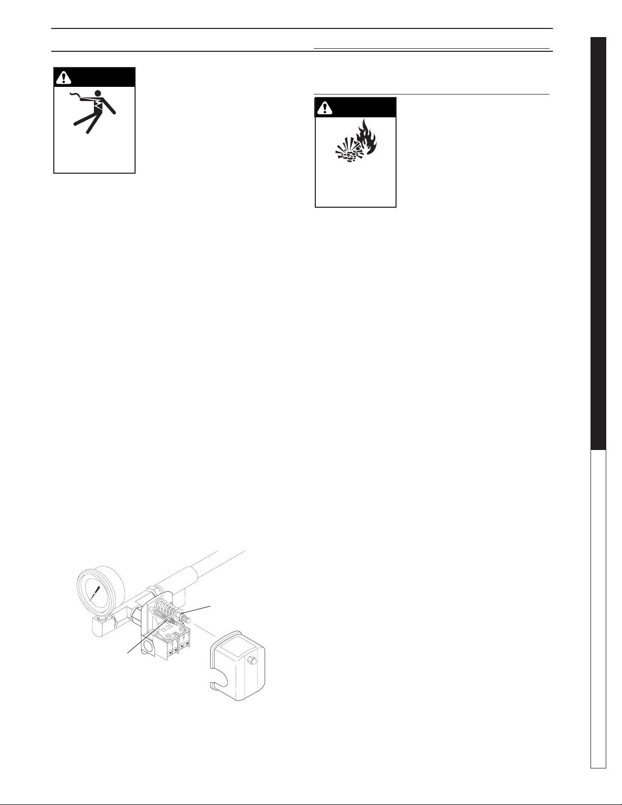
Remove cover of the pump pressure control switch to
allow access to the two nuts used to adjust the pump
operating pressure. The pressure switch on Water
Maze equipment is set at the factory and should not
have to be adjusted at start-up, but will need to be
verifi ed at start up and maintained regularly at least
monthly.
1. The nut on the larger spring in the pump pressure
switch, adjusts the pump cut in (cut on) and pump
cut out (cut off) pressures simultaneously.
2. The nut atop the smaller spring in the pump pres-
sure switch only controls the cut out range and
is used to narrow or widen the gap between the
pump cut in and cut out pressures.
3. To cycle the pump less frequently, the gap should
be as wide as possible while still allowing the
pump to shut off quickly when all outlets are
closed. Adjust the smaller spring to widen the
gap between pump in and out (on and off). 4045 PSI (CLP, Rec2-20) or 30 PSI (EC1-300A) is
desirable. Adjusting the larger spring should not
be necessary.
4. When making pressure switch adjustments, make
sure all pump outlets are off or closed, except for
the one outlet valve used to relieve and build pressure while making pressure switch adjustments.
Controls
Cut in/Cut out
Controls
Cut out Range
8913970-39
8.913-970.0 - L • WATERMAZE CLP 5024/7034
PRESSURE TANK
OPERATION
WARNING
RISK OF
EXPLOSION:
INSTRUCTIONS WHEN
CHANGING PRESSURE
FOLLOW
AVERTISSEMENT: Après avoir effectué l'entretien
du réservoir, il est nécessaire de passer à une
pression de précharge supérieure en raison d'un
changement requis du paramètre du pressostat;
le non-respect des directives ci-dessous peut
causer une rupture ou une explosion, et pourrait
causer des lésions corporelles graves ou fatales
et/ou des dommages à la propriété.
• Do not adjust or add pressure if there has been a
loss of air.
• Do not adjust the pre-charge pressure if there is
visible exterior corrosion.
• Do not adjust the pre-charge pressure if there has
been a reduction of the pump cycle time or the
pre-charge pressure compared to its initial setting.
A reduction in pump cycle time can result from
loss of tank corrosion and any re-pressurization
or additional pressure could result in rupture or
explosion.
• Pressure tank pressure is factory set but will have
to be checked regularly (at least monthly). Use
an air pressure (tire) gauge. Before checking air
pressure on the pressure tank, purge all water out
of the tank by turning the pump on and pumping
all water out of the pressure tank.
1. Our transfer pump water systems use a water
pressure tank and water pump with these two
pressure operation ranges:
Cut in (start pumping): 20 PSI
Cut out (stop pumping): 30 PSI (EC1-300A)
Cut out (stop pumping): 40-45 PSI (CLP, REC2-20)
2. Typical factory set air pressure on bladder-type
residential water pressure tanks are shipped from
the factory with a standard pre-charge of:
18 psig for models WX-101 and WX-102
18 psig for models WX-103 and WX-203
18 psig for models WX-205 and WX-350
3. Set the well tank air pressure to 2 PSI below the
pump pressure switch cut-in pressure. This is
usually 18 PSI.
WARNING! When the tank has
been in service and a change
to a higher pre-charge pressure
is necessary because of a required change in the pressure
switch setting, failure to follow
instructions below can cause a
rupture or explosion and could
cause serious or fatal personal
injury and/or property damage.
OPERATOR’S MANUAL
13

PROGRAMMING INSTRUCTIONS
The heart of the CLP Automatic Maintenance System,
the AMC Controller, has been pre programmed at the factory with Maintenance Modes described in the Program
Schedule shown below. In order for the CLP wastewater
system to function properly, the controller clock must be
set with the correct time-of-day and date.
Setting the Clock
After the time-of-day and date are set, the Automatic
Maintenance System will automatically control the operation of your CLP and provide daily scheduled maintenance in accordance with the Program Schedule below.
If electrical power is cut from the CLP, the AMC Controller will retain its program for 7 days. If electrical power
is not reconnected within 7 days, then the time-of-day,
month and year must be reset.
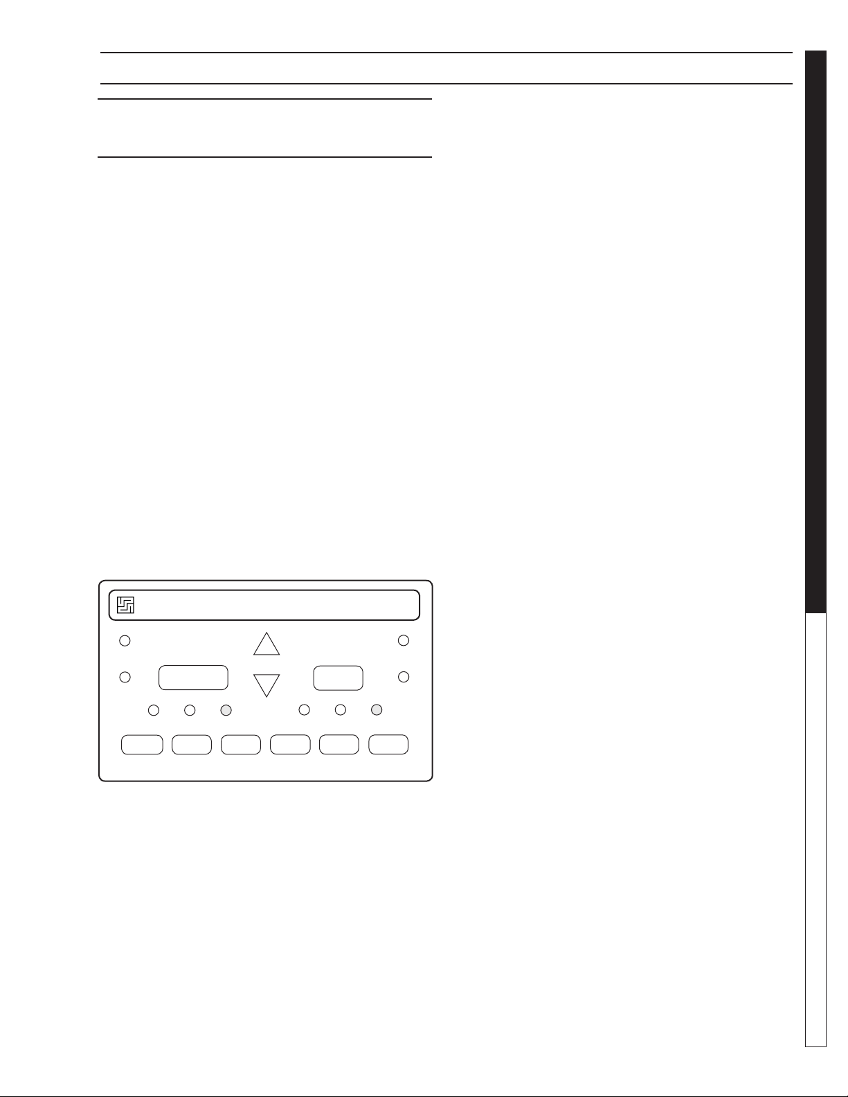
1. Press the ESC key located next to the display win-
dow and under the arrow key pad (see fi gure below).
Pressing the ESC key will access the Parameter
OPERATOR’S MANUAL WATER TREATMENT SYSTEM
Assignment Menu.
2. Using the up/down arrow keys ▲ or ▼, move the
cursor to highlight ‘Setup’ and press OK to accept.
3. Move the cursor to highlight ‘Clock’ and press OK to
accept.
Program CardParameter Assignment Menu
Mo 10:15
2006-10-13
4. Move the cursor to highlight ‘Set Clock’ and press
OK to accept.
ESC OK
Arrow
Key Pad
NOTE: When setting time on clock, use only military time.
NTP
Set Clock
S/W Time
5. Move the cursor to the value wanting to be changed
using the left/right arrow keys or , and change
the value by using the up/down arrow keys ▲ or ▼.
Set Clock
Mon. 10:15
YYYY-MM-DD
When you are done setting the time and date press
OK to accept your changes.
6. Press ESC three times to exit to the main menu.
Program Schedule
The Automatic Maintenance Controller has been preprogrammed to the Program Schedule on the next page
with Mode #1 starting at 12:00 midnight and continuing
through all 6 maintenance modes to 4:16 a.m. If needed,
the Mode start time and run times may be changed to
suit a specifi c application. We suggest that you consult
a factory representative prior to making any changes to
the Program Schedule.
14
Stop
Program
Setup
Network
Diagnostics
Msg Cong
Start Screen
Clock
LCD
Menu Language
Switch to OP
VALVE LOCATION &
8.913-970.0 - L • WATERMAZE CLP 5024/7034

PROGRAMMING INSTRUCTIONS
Maintenance
Mode Description Start Time Run Time Program Name
1 Media Filter Backwash 12:10 a.m. 30 minutes MMB Time 1
2 Carbon Filter Backwash 12:45 a.m. 30 minutes CRB Time 1
3 System Recirculation 1:30 a.m. 1.5 hours SR Time 1
4 Filter Recirculation 3:15 a.m. 1 hour FR Time 1
5 Automatic Sludge Dump 4:16 a.m. 1 minute P Time 1
6 Ozone Circulation 11:00 p.m. 5 hours Oz Time 1
WATER TREATMENT SYSTEM
Manual Start/Run:
Overriding the automatic maintenance schedule and
manually starting any of the Modes above can be done
in two ways:
1. To manually start and run any of the six maintenance
modes as shown in the Program Schedule above,
reset the AMC time-of-day clock to the start time as
shown in the schedule. For example, to manually
start the Media Filter Backwash cycle, temporarily
reset the AMC clock to 12:00 midnight. Don't forget
to set the clock back to its true time of day.
2. Maintenance Modes 1 through 4 are used by
WaterMaze personnel to test each CLP before it
leaves the factory, these four modes can be manually
started and run by following these instructions.
a. From the date and time screen hit the
left arrow and you'll see "ESC + C" displayed.
b. From the " ESC + C" screen follow the chart
below for the mode you want to test. For example to
start the Media Filter Backwash fi rst hit the "ESC"
button followed by the up arrow (
second delay between the two. Each mode will run
for 2 minutes to give time to check for proper operation,
set fl ows and etc.
▲), about a 1/2
OPERATOR’S MANUAL
Maintenance Mode
1
2
3
4 Filter Recirculation ESC FR Time 1
Description Button Button Program Name
Media Filter Backwash ESC MM TIme 1
Carbon Filter Backwash ESC CRB Time 1
System Recirculation ESC SR Time 1
8.913-970.0 - L • WATERMAZE CLP 5024/7034
▲
▲
▲
▲
15

VALVE INSTRUCTIONS
FUNCTION:
It is extremely important to know the location and function of the valves on the CLP. Improper positioning of
the valves can cause overfl ow or damage which could
result in time consuming clean-up and repairs. Study the
section on “Valve Location and Function.”
• Valve 1 - Flow Control Valve
This valve controls the amount of water allowed
into the CLP from the sump pump. Adjust 2-4 gpm
above your demand on the system (See Pages
13, 58).
• Valves 2 & 3 - Ozone Pump
Should be open at all times (See pages 19, 42,
44).
NOTE: Only to be closed when removing or re-
placing the ozone pump.
OPERATOR’S MANUAL WATER TREATMENT SYSTEM
• Valve 4 - Oil Skimming Bucket
Valve should be closed except when draining
off oil (See pages 13-14).
• Valve 5 - Tank Valve
This valve should be open at all times except when
removing air valve for repair (see pages 13-14).
• Valve 6 - Rinse Water Control Valve
This valve is opened only when rinse water is
needed (See page 44).
• Valve 7 - Outlet to Pressure Washer Valve
After start-up, this valve is left fully open all of
the time. Controls water to the pressure washer
(See page 44).
• Valve 8 - Rain Water Overfl ow Valve
Left open partially. When SV#1 opens, water is
allowed to discharge while still providing water for
the pressure washer (See page 44).
• Valve 9 - Recycle Flow Control Valve
This valve is used to control the volume of
water going back to the collection pit for recycling
through the system when the PLC or AMC activates the solenoid, SV3, for recycling the system.
Open partially to match fi lter fl ow meter allowing
a smooth fl ow without cycling transfer pump as
much as possible (See pages 46, 66).
• Valve 10 - Filter Flow Control Valve
This valve controls the amount of water allowed
to fl ow through the fi lters. Adjust to the same or
2 gpm below valve #1 (See pages 36, 62).
• Valve 11 & 12 - Filter Control Valve
When set on Filter, this valve allows water to pass
through the fi lter. When set on Backwash, the
water passes through the fi lter in reverse, then
passes back to the catch basin. The air valves
control these valves (See pages 13-14).
• Valve 13
Should be open at all times. Allows pressur-
ized water to fl ush sediment from the cone tank
(See pages 13-14).
• Valve 14
16
8.913-970.0 - L • WATERMAZE CLP 5024/7034

This valve should be open at all times to allow
pressurized water to fl ush out the sludge hose
(See pages 14, 38, 66).
Valve 16
Should be open at all times. Allows fresh water
into tank 2 when SV#2 opens. Valve should be
fully open (See page 44).
Valve 17
In the recirculation mode, this valve is used to
control the volume of water going to tank #1 when
the PLC or AMC opens SV#4. Open partially to
match fi lter fl ow meter allowing a smooth fl ow
without cycling transfer pump as much as possible
(See pages 38, 66).
Valve 20
Should be open partially to control the amount
of water fl ow to backwash the multi-media fi lter
when the PLC or AMC opens SV#7. Set for 30
gpm (See pages 36, 62).
Valve 21
Should be open partially to control the amount of
water fl ow to the backwash carbon fi lter when the
PLC or AMC opens air solenoid valves. Set for
15 gpm (See pages 40, 56).
WATER TREATMENT SYSTEM
OPERATOR’S MANUAL
8.913-970.0 - L • WATERMAZE CLP 5024/7034
17

OPERATOR’S MANUAL WATER TREATMENT SYSTEM
Tank #1
Control Panel
CLP-5024 OPERATION VIEW
Orp/pH
Probes
STEP
R
ON THIS PLATFORM
PRECAUTION/ATTENTION
DO NOT STAND O
WARNING
WARNING
DO NOT STAN
PRECAUTION/ATT
ON THIS PLATF
D
ENTI
OR STEP
ON
OR
M
Valve
2
300 Gallon Cone
Bottom Tank
Junction Box
Valve 1
Tank #2
Valve 11
Multi Media
Filter
Valve 21
Carbon
Filter
Inlet
Line
Sump
Pump
Sump Pump
Installation
(3 Phase)
Valve 12
Sump
Pit
FS1
FS2
FS7
Oil
Decanter
Barrel
Inlet
Line
Sump
Pump
Sludge Tub
Flow
Meter
Valve 13
Valve 5
Valve 4
Sump
Pit
FS1
FS2
18
Sump Pump Not Supplied
with Machine. See
Specifi cation on Page 70.
Sump Pump
Installation
8.913-970.0 - L • WATERMAZE CLP 5024/7034
89139700-5
CLP-7034 OPERATION VIEW
WATER TREATMENT SYSTEM
Flow Meter
Orp/pH Probe
Control
Tank #2
Tank #1
Panel
Valve 12
Valve 5
Valve
14
600 Gallon
Cone Bottom
Tank
Sludge
Tub
Valve 4
Oil
Decanter
Barrel
OPERATOR’S MANUAL
Multi-Media
Filter
Carbon Filter
3-Way Ball Valve
Assembly
8.913-970.0 - L • WATERMAZE CLP 5024/7034
Junction Box
Valve 13
89139700-25
19
OPERATOR’S MANUAL WATER TREATMENT SYSTEM
WATER PANEL INSTALLATION
SV1
SV2
To Fresh Water Line
To Sewer or Storage
To Pressure Washer
89139700-31
20
8.913-970.0 - L • WATERMAZE CLP 5024/7034
STANDARD ORP/PH CONTROLLER
WATER TREATMENT SYSTEM
STANDARD ORP/PH DIGITAL
CONTROLLER - MODEL 250
Operation
The Oxidation Reduction Potential (ORP) and pH of the
water stream are controlled automatically by the digital
controller. The controller receives input from the ORP
sensor on the activity of the sanitizer and input from the
pH sensor on the pH level of the waste stream. The level
of ORP and pH being sensed, and the requested levels
programmed in the controller will determine if outputs
from the controller are sent to the feed pumps. If sanitizer or pH adjust are needed, the output will turn the
corresponding feed pump on. This will inject the required
sanitizer or pH until programmed levels are reached and
feed pump will stop.
If ORP or pH adjustment is needed the ozone pump will
also turn on. The chemical is injected at the outlet of the
ozone pump. If ORP is needed the controller also turns
on the ozone generator. All will run until setpoint levels
are reached.
Acid/Base Switching
Because most systems are dealing with a high pH situation, the controller is factory set for acid feed. If you
require a base feed, open plastic door on controller and
ORP Control Setpoint
The ORP setpoint is factory set at 550 mV, which is
recommended to maintain water quality by killing germs
and bacteria. There is no need for ORP calibration.
The sanitizing concentration required to generate a
desired ORP value varies with pH and overall water
quality, particularly Total Dissolved Solids (TDS) concentration and organic load.
To change the ORP control setpoint:
• Press [SETPOINT],
• Press [ORP]: the display fl ashes,
• Use the [UP] and [DOWN] arrows to adjust the
ORP value,
• Press [SETPOINT] again to save the new value.
pH Calibration
To calibrate the pH, use a reliable, fresh test kit (Phenol
Red). Note the value of the pH and compare it to the
display value.
To change the pH calibration:
• Press [CALIBRATION],
• Press [pH]: the display fl ashes,
• Use the [UP] and [DOWN] arrows to adjust the
pH value,
• Press the [CALIBRATION] again to save the new
value.
OPERATOR’S MANUAL
WATER MAZE ® 250
FEED
ALARM
PROPORTIONAL
CONTROL
MANUFACTURED BY SANTA BARBARA CONTROL SYSTEMS - SANTA BARBARA CALIFORNIA 93111 USA
ORP
OFF MANUAL AUTO
SAFETY
TIMER
SETPOINT
CALIBRATION
24V 50/60Hz 5A
pH
ORP / pH
DIGITAL CONTROLLER
pH
OFF MANUAL AUTO
LOW LIMIT HIGH LIMIT
FEED
ALARM
push the up and down arrows at the same time and let
go. To toggle between acid (Ac) or base (bA) push the
up arrow once then let the controller go though its start
up procedure. Close plastic door.
Feed Mode
The feed mode for the pH and sanitizer can be set to
"OFF", Manual or Automatic. Set to Automatic. To select
the desired feed mode, press [ORP] or [pH] until the
corresponding LED indicator light is illuminated. There
is a short delay before activation. NOTE: Holding the
switch for more than 5 seconds resets the setpoint and
calibration for [ORP] or [pH] to original factory values.
pH Control Setpoint
The pH setpoint is preset at 6.8. To change the pH
control setpoint:
• Press [SETPOINT],
• Press [pH]: the display fl ashes,
• Use the [UP] and [DOWN] arrows to adjust the
pH value,
• Press [SETPOINT] again to save the new value.
8.913-970.0 - L • WATERMAZE CLP 5024/7034
21

SENSOR MAINTENANCE
Out-of-Range Alarms
The out-of-range alarms are factory set at 450 to 650
mV for ORP and 6.5 to 7.5 for pH. If the ORP is below
the low limit, the red LED alarm fl ashes but the sanitizer
feed continues.
If the pH limits are exceeded, the red LED alarm fl ashes
and the pH feeder continues.
To change an alarm limit:
• Press [LOW LIMIT] or [HIGH LIMIT],
• Press [ORP] or [pH]; the display fl ashes,
• Use the [UP] and [DOWN] arrows to adjust the value,
• press [LOW LIMIT] or [HIGH LIMIT] again.
CAUTION: Increasing the out-of-range limits may
cause overfeeding of chemicals.
ORP AND PH SENSOR
OPERATOR’S MANUAL WATER TREATMENT SYSTEM
The controller is virtually maintenance free. The enclosure and front panel can be cleaned with a soft cloth
moistened with a mild soap and water solution or a glass
cleaner. Do not use abrasives or harsh chemicals.
Sensor Cleaning/Testing
The sensor tips must be kept clean and free from
chemical deposits and contamination to function properly.
After saturation in the waste
stream, the sensors may need
to be cleaned on a weekly or
monthly basis depending on
the water quality and other
facility-specifi c characteristics.
Slow response and inconsistent readings are indications
that the sensors are in need
of cleaning.
To clean a sensor, carefully
remove it from the compression fi tting or holding bracket.
Clean the tip of the sensor with a mild liquid detergent
(Joy®, etc) solution. Rinse with fresh water and soak the
sensor in a mild acid solution for fi ve minutes. Rinse with
fresh water and reinstall the sensor.
MAINTENANCE
66-123 66-122
To check sensor for proper operation place a small
amount of white vinegar, muriatic or hydrochloric acid
into a cup and place sensor probe into solution. For the
pH sensor, the needle should drop. For the ORP sensor,
the needle should rise.
NOTE: Only clean one sensor at a time. Sensors must
stay in some kind of liquid at all times.
Sensor Replacement
For preventative maintenance it is also recommended
to replace the sensors on an annual basis or as performance diminishes.
Sensor Storage
Extended exposure to atmospheric conditions will cause
the sensor tips to dry out. Always remove and properly
store the sensors if they are to be winterized or inactive.
Store the sensors with the original cap provided, making
sure that each cap is fi lled with clean water. If the storage containers have been misplaced, store the sensors
individually in small glasses or plastic containers with
clean water covering the sensor tips.
Terminal Block Wiring
B W G
B W G
B W G
ORP R W B Power pH
Rotary
Flowswitch
B=black, W=white, G=green, R=red
Dry-Contact
Alarm
22
8.913-970.0 - L • WATERMAZE CLP 5024/7034

TROUBLESHOOTING - ORP/PH SENSORS
All controllers are manufactured to the highest quality standards and thoroughly tested before leaving the factory.
State-of-the-art designs and fabrication technology should ensure years for trouble-free operation.
PROBLEM SOLUTION
WATER TREATMENT SYSTEM
NO LIGHTS ARE
ON WITH
POWER ON
ILLOGICAL pH AND
ORP VALUE DISPLAYS
ORP FEEDER
DOES NOT
ACTIVATE
pH FEEDER
DOES NOT
ACTIVATE
pH REQUIRES
FREQUENT
CALIBRATION
Check for power going to controller.
Check for damaged power connector.
Check internal fuse (1A slow blo) marked F3 on control board.
The sensor cable connections may be reversed. Verify that the sensor
cables are properly connected to their respective BNC connectors
on the controller unit.
Make sure the AUTO feed light for ORP is on.
Check the ORP setpoint.
Check ORP relay fuse (5A slow blow) marked F2 on control board.
Verify that the acid/base feed jumper JP14 on the control board is properly set.
Make sure the AUTO feed light for pH is on.
Check the pH relay fuse (5A slow blow) marked F2 on control board.
Clean or replace the sensor as outlined in the maintenance section.
OPERATOR’S MANUAL
INCONSISTANT
OR SLOW pH OR ORP
READINGS
CHEMICAL FEEDER
RUNS CONTINUOUSLY
Verify that the sensor cables are properly connected to their
respective BNC connectors and the controller unit.
Clean or replace the sensor as outlined in the maintenance section.
Replace the sensors if needed.
Make sure the AUTO feed mode is selected.
Verify that the chemical feeders are properly connected to their
respective connectors or controller unit.
8.913-970.0 - L • WATERMAZE CLP 5024/7034
23

METERING PUMP
VSP20 METERING PUMP
#5-2359
(Variable Speed Peristaltic)
TECHNICAL INFORMATION
Materials:
Pump Head .................................. Polycarbonate
Pump Head Tubing .....Special Synthetic Rubber
Strainer and Injection Point Fitting ...............PVC
Feed Rate: 2.6 - 20 GPD
Tubing Size: 7/16" O.D. x 1/4" I.D.
Dimensions: Hgt. = 5", Wdt. = 6-1/4", Dpt. = 7"
Standard Accessories Provided with Pump:
Head Tubing
Injecting Fitting with Check Valve
Strainer
OPERATOR’S MANUAL WATER TREATMENT SYSTEM
Polyethylene Tubing (1/4" O.D. x 15')
Tubing Sleeve (for strainer connection)
Electrical Rating:
24V
.3 Amps
50/60 Hz
Maximum System Pressure: 25 PSI
(maximum allowable at injection fi tting)
24
8.913-970.0 - L • WATERMAZE CLP 5024/7034
GENERAL MAINTENANCE & SERVICE
GENERAL MAINTENANCE
AND SERVICE
Periodic Maintenance:
• Oil Skimmer Collection Drum
• Monitor the level of oil in the collection drum.
Empty it as required.
• Check the electrical cords to ensure they are safe,
no damage or cracking.
• Check inlet / outlet pipes for leaks or damage.
Winterizing
If a heated area is not provided in areas where freezing
temperatures can be expected, the entire machine must
be drained.
Testing Carbon
Remove the valve from the Carbasorb Filter and extract a
carbon sample. Place carbon sample in the 4 oz. plastic
bottle. (Fill the bottle 1/4 full of carbon, about 2 inches).
Fill the 2 oz. bottle with water and add 1 drop chlorine.
Dip the chlorine test paper into the solution to ensure
you have at least 100 parts per million of chlorine in the
mixture. Add this solution to the carbon in the 4 oz. bottle.
Cap and shake it periodically over a period of three minutes. After three minutes, dip a new piece of chlorine test
paper into the solution. Compare the color with the color
chart that comes with the test paper. If the color matches
the color on test paper, order new carbon. There may
be some dark discoloration from the carbon. Do not
confuse this with the color caused by the chlorine.
OZONE GENERATOR
Ozone...Nature’s Purifi cation Agent
Ozone is produced in nature or artifi cially by man. In
the earth’s atmosphere, ozone is formed when oxygen
is exposed to ultraviolet light or an electrical charge as
during thunderstorms. Ozone’s primary function in nature
is to purify the air we breathe and screen us from harmful
rays of the sun. In a similar fashion, the CLP system uses
ozone to disinfect water because
of characteristics that make it ideal for water treatment.
Ozone’s Characteristics
Ozone is well suited for water treatment, and it’s unique
characteristics are described below:
Ozone has a number
•
Ozone works up to 3,000 times faster than chlorine
to kill bacteria and destroy harmful microorganisms.
• Ozone is a more powerful oxidizing agent than
chlorine and bromine, having a better ability to
remove water contamination.
• Ozone will not form harmful by-products, like
THM’s (a problem in drinking water), or chloramines, (by-products of chlorine that are responsible for odors, skin irritations and burning eyes.)
• Ozone will not alter the water’s pH, reducing pH
fl uctuations.
• Ozone coagulates small particles in water so
clarity is dramatically improved.
• Ozone acts as a deodorizer removing unpleasant
odors from water.
How the CLP Ozone System Works
Because ozone is unstable, it cannot be packaged and
used at a later date. For this reason, ozone is always
produced where it is utilized.
Point-of-use ozone generation is simple. This powerful
disinfectant is produced from ambient air surrounding the
generator using special ultraviolet lamps located inside
the system’s cabinet. To generate the ozone, air movement is created through the use of an air compressor or
water venturi. As air passes over these unique lamps,
the oxygen contained in the air is converted. The resulting ozone gas is subsequently introduced to the water
in the inlet pipeline, where oxidation and disinfection
immediately takes place.
Ozone Generator Maintenance
WARNING: Never look at an un-
WARNING
EYE HAZARD:
NEVER LOOK
AT UNSHIELDED
OZONE LAMP
Lamp: The light has a 9,000 hour life expectancy.
shielded ozone lamp while operating the unit. This lamp will cause
severe eye and skin damage.
There is a green indicator light
which will dim when the unit is
operating properly and will turn
bright green if there is a malfunction. See product description for
location of the indicator light.
ULTRAVIOLET LIGHT
COMPLIANCE
Ultraviolet Light Safety Requirements
The device used in this product is a Class 1 certifi ed
ozone generator product. Operating this product outside
specifi cations or altering its original design may result
WATER TREATMENT SYSTEM
Troubleshooting Guide
8.913-970.0 - L • WATERMAZE CLP 5024/7034
25
OZONE SPECIFICATIONS
in hazardous radiation exposure, and may be considered
an act of modifying or new manufacturing of a laser
product under U.S. regulations contained in 21CFR
Chapter 1, subchapter J.
CAUTION: Avoid exposure to direct or strongly
refl ected germicidal ultraviolet rays.
DO NOT STARE INTO BEAM.
ATTENTION: Éviter l'exposition aux rayons ultra-
violets germicides fortement réfl échis.
NE PAS REGARDER DIRECTEMENT LE FAISCEAU.
DANGER: Ultraviolet radiation. Disconnect
OPERATOR’S MANUAL WATER TREATMENT SYSTEM
Power Before Replacing Lamp.
ATTENTION: Radiation ultraviolette. Débrancher
l'alimentation avant de remplacer la lampe.
DANGER: Connect only to a circuit that is protected by Ground Fault Circuit Interrupt (GFCI).
DANGER: Raccorder uniquement à un circuit qui
est protégé par un disjoncteur différentiel de fuite
à la terre (DDFT).
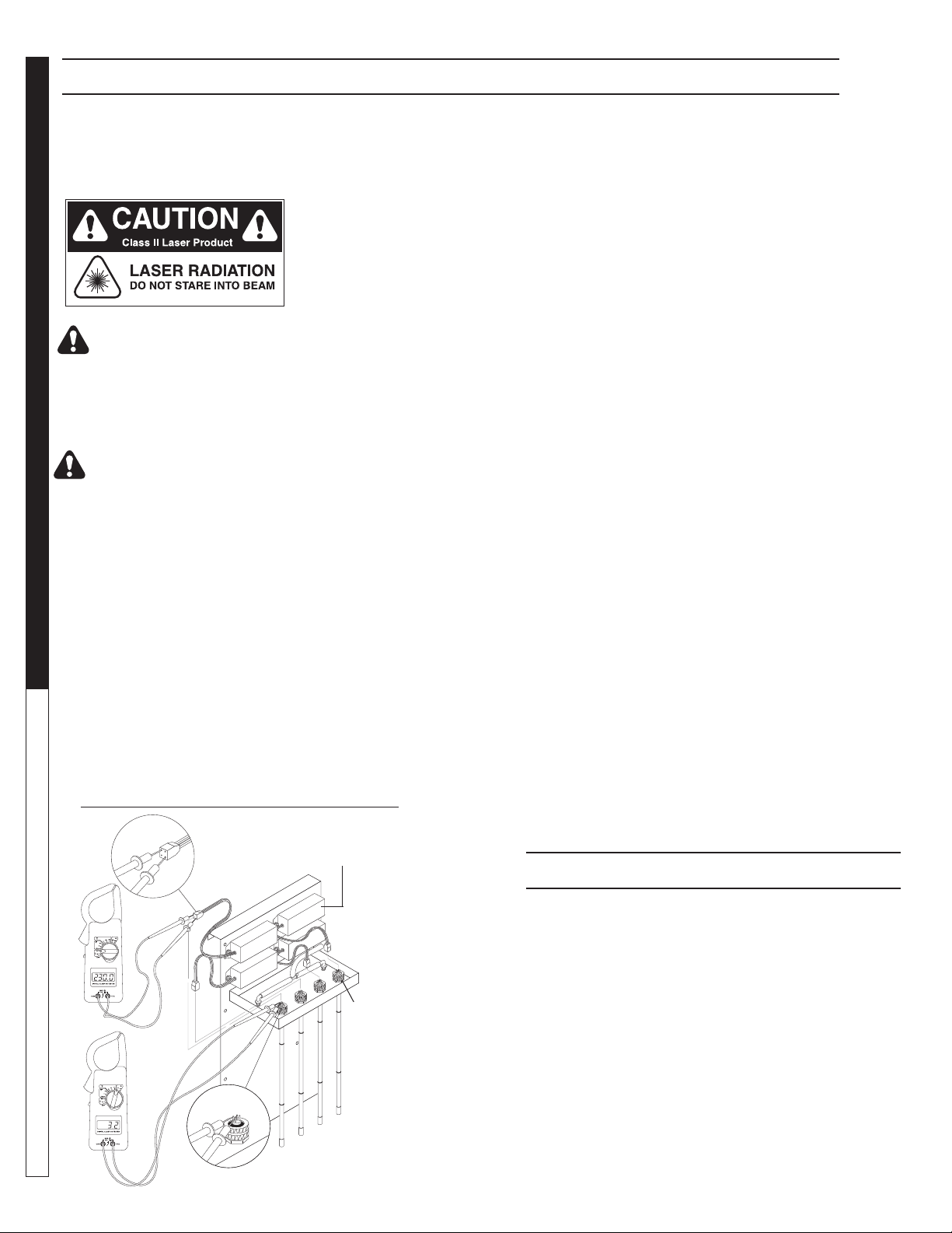
Testing the Lamp:
(See Ozone Generator Testing Illus.)
To test the ozone lamp, use a voltmeter set on ohms.
First remove the ozone cover and unplug the lamp plug
from the ozone lamp.
OZONE GENERATOR TESTING
Four Pin
Connector
Ballast
NOTE: There are two fi laments - an upper and a lower -
inside the lamp. Place one of the voltmeter leads on one
of the lamp prongs and, with the other lead, touch all of
the three remaining prongs. If continuity is not achieved
on both upper and lower fi laments, replace the ozone
lamp (Part #6-0534)
To test the power pack, use a voltmeter set on the correct voltage (120V or 240V). Place one of the voltmeter
leads into the lamp plug where the white wire goes into
it and plug the other voltmeter lead into the lamp plug
where the blue wire goes into it. If no voltage is present
replace the ozone ballast (Part #6-05231 - 120V, Part
#6-05232 - 240V). When ordering an ozone ballast, you
also need the 4-pin connector (Part #6-05233).
Replacing the lamp:
(See Ozone Generator Breakdown)
Lamp replacements are available from your WATER
MAZE Dealer should they need to be replaced. Simply
turn off the power to the CLP at the breaker, remove the
screws on the power pack cover and remove the cover.
Disconnect the plug on the end of the ozone lamp. Now,
loosen the lamp holder locking ring from around the end
of the lamp by turning it counterclockwise and remove
it. Remove the lamp by grabbing the rubber bushing
around the end of the lamp and pulling it straight out.
Remove the rubber bushing from the lamp and install
it on your new lamp, making sure the outer edge of the
bushing is fl ush with the outer edge of the silver end cap
on the lamp. Now, slide the lamp back into the reaction
chamber. The lamp holder may now be reinstalled and
tightened. Reinstall the plug onto the lamp and replace
the power pack cover.
CAUTION: Keep the lamp free of fi ngerprints and
dust particles by only handling the metal end caps
on the lamp. You can clean the lamp with rubbing
alcohol and a soft cloth. A dirty lamp will not allow
maximum ozone output.
SPECIFICATIONS
26
Energy required 110V:
105VAC MIN., 125VAC MAX., .800 AMP/Ballast
Energy required 220V:
210VAC MIN., 230V MAX., .450AMP/Ballast
Ozone
Lamp
Prongs
Power Consumption: 20 Watts
Average Lamp Life: 9,000 Hours
Lamp Wave length: 185 nm
89139700-34
8.913-970.0 - L • WATERMAZE CLP 5024/7034
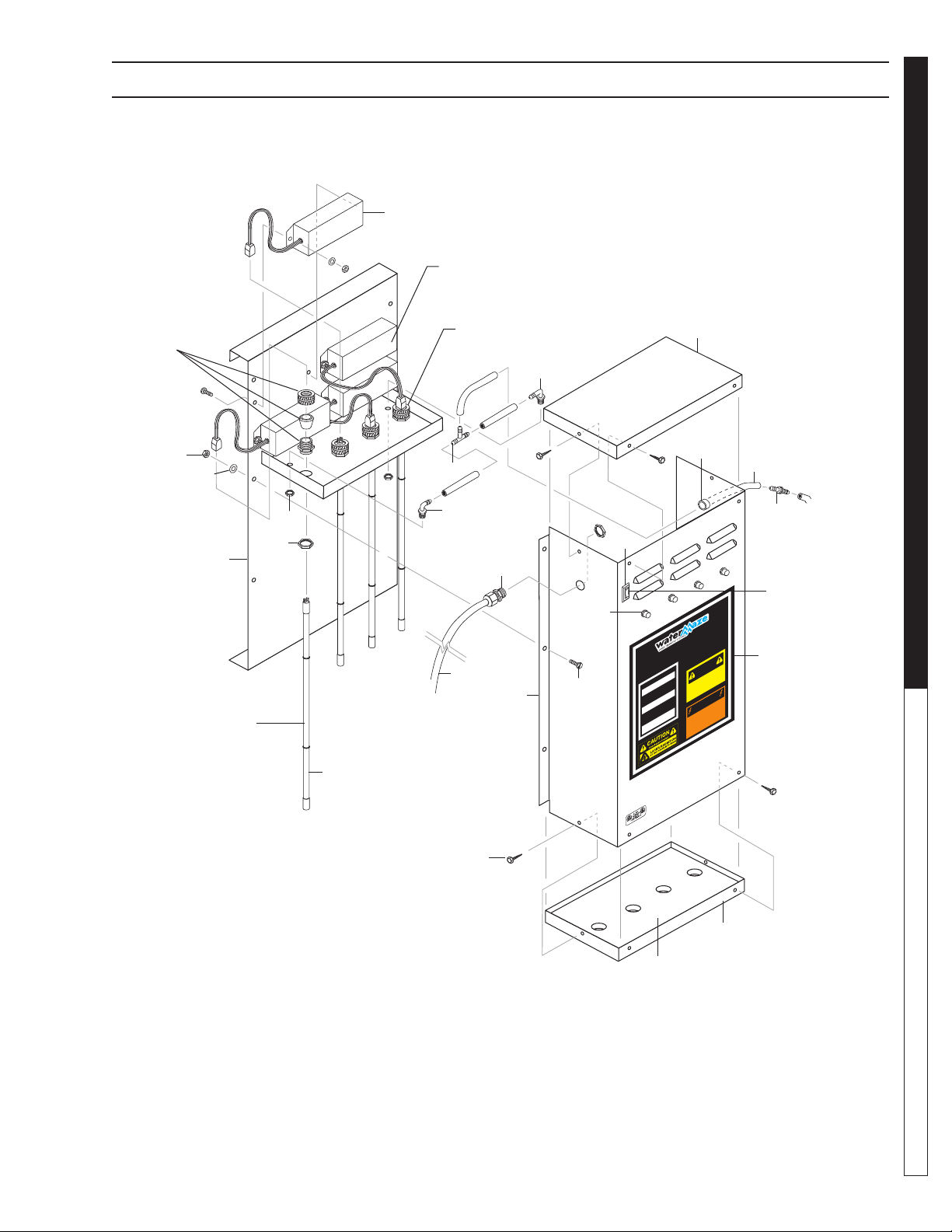
OZONE GENERATOR BREAKDOWN EXPLODED VIEW
21
Ballast
WATER TREATMENT SYSTEM
5
Prongs
Ozone Lamp
19
OPERATOR’S MANUAL
11
9
23
10
4
1
12
11
16
17
13
14
6
On/Off
Switch
8
Ozone
Lamp
15
3
UCION
N
AUTION
A
C
PREC
IGHT OPERATIO
L
.
e
v
uous light indicates UV
ecti
f
mador está def
r
o
f
TEUR
A
o
f
rans
ATTENTION
OT!
H
!
UD!
ALIENTE!
A
C
H
C
.
o
ectuos
mateur est
r
ENT
TT
A
/
!
ARNING!
W
ION
VICING.
VICING.
R
R
!
ENC
OM ELECTRICAL
OM ELECTRICAL
R
T
R
A
VICI
VICI
R
Y BEFORE SE
Y BEFORE SE
L
L
AR SE
AR SER
D
AR
D
PAR
DISCONNECT F
P
DISCONNECT F
TION ÉLECTRI
TION ÉLECTRI
SUPP
SUPP
TA
TA
ANTES DE
ANTES DE
L’ALIMEN
L’ALIMEN
AIRE UNE RÉ
AIRE UNE RÉ
DESCONECTE LA CORRIENTE ELECTRICA
DESCONECTE LA CORRIENTE ELECTRICA
F
F
COUPER
COUPER
ANT DE
ANT DE
AV
AV
ON!
I
.
.
UE
UE
O
O
Q
Q
TION.
TION.
A
A
8.900-455.0
OZONE GENERATOR
INDICATOR
ight contin
2
22
r
A b
light or ballast de
INDICADORA
OPERACION DE LA LUZ
ans
r
Una luz luminosa indica que la luz ultravioleta o t
INDIC
OPÉRATION DE LE LAMPE
Une lumière claire indique que la lumière
aviolette ou le t
r
ult
défectueux.
7
24
8.913-970.0 - L • WATERMAZE CLP 5024/7034
18
20
89139700-26
27
 Loading...