


Assembly and
Operating Instructions
Sand lter system SF 122 - 124
(Sand lter system small without pre-lter)
English
Illustrations are exemplary.
Sand lter system
Please read this manual carefully and
keep it for future reference.

2
> 3 m
selbst-ansaugend
132
4
D
UK
F
I
NL
S
CZ
SK
SI
HU
RO
D
UK
F
I
NL
S
CZ
SK
SI
HU
RO
D
UK
F
I
NL
S
CZ
SK
SI
HU
RO
D
UK
F
I
NL
S
CZ
SK
SI
HU
RO
Assembly and Operating Instructions Sand Filter System without Pre-lter
KURZANLEITUNG / QUICK START GUIDE / NOTICE SOMMAIRE / GUIDA RAPIDA BEKNOPTE HANDLEIDING / KORTFATTAD BRUKSANVISNING /
STRUČNÁ PŘÍRUČKAG / STRUČNÝ NÁVOD / KRATKA NAVODILAG / GYORS ÚTMUTATÓ ÎNDRUMĂTOR PE SCURT
Eigenschaft
der Pumpe: nicht-ansaugend
FI
Standort der Filteranlage wählen
Selecting the lter system location
Sélection du lieu d‘implantation de l‘installation de ltrage
Scegliere la collocazione del ltro
Positie van de lterinstallatie kiezen
Välj var ltret ska stå
Zvolte umístění lračního systému
Zvoľte miesto ltračného zariadenia
Izbira mesta postavitve ltrirne naprave
A szűrőberendezés felállítási helynek megválasztása
Selectarea locului de amplasare al instalaţiei de ltrare
Filteranlage montieren
Installing the lter system
Montage de l‘installation de ltrage
Montare il ltro
Filterinstallatie monteren
Montera lteranläggningen
Smontujte ltrační systém
Namontujte ltračné zariadenie
Montaža ltrirne naprave
A szűrőberendezés összeszerelése
Montarea instalaţiei de ltrare
Filteranlage muss unterhalb des Wasserspiegels stehen
Filter system must be positioned below water level
Le système de ltration doit être sous le niveau de l‘eau
Il ltro deve essere collocato sotto il livello dell‘acqua
Filtersysteem moet zich onder het waterniveau bevinden
Filteranordningen måste stå under vattenytan
Filtrační systém je nutno namontovat pod hladinou vody
Filtračné zariadenie musí stáť pod vodnou hladinou
Filter mora biti postavljen pod ravnijo vode
A szűrőberendezésnek a vízszint alatt kell elhelyezkednie
Instalaţia de ltrare trebuie să se găsească sub nivelul oglinzii apei
innenaußen
Entleerungsventil festschrauben
Fixing the drain valve
Fixation de la vanne de vidange
Avvitare la valvola di scarico
Aftapventiel vastschroeven
Skruva fast tömningsventilen
Přišroubujte výpustný ventil
Priskrutkujte výpustný ventil
Privitje ventila za izpraznitev
Az ürítőszelep rögzítése
Înşurubare fermă supapă de golire

Assembly and Operating Instructions Sand Filter System without Pre-lter
576
8
D
UK
F
I
NL
S
CZ
SK
SI
HU
RO
D
UK
F
I
NL
S
CZ
SK
SI
HU
RO
D
UK
F
I
NL
S
CZ
SK
SI
HU
RO
D
UK
F
I
NL
S
CZ
SK
SI
HU
RO
1
3
2
4
SteigrohrFilterstern
3
Steigrohr einsetzen (2 unterschiedliche Versionen)
Insert riser pipe (2 different versions)
Remplacer le tube montant (2 versions différentes)
Inserire il tubo montante (2 versioni diverse)
Stijgbuis toepassen (2 verschillende versies)
Sätt i stigröret (2 olika utföranden)
Nasazení stoupací trubky (2 různé verze)
Nasadiť stúpaciu rúru (2 rôzne verzie)
Vstavite dvižno cev (2 različni različici)
A felszállócső behelyezése (2 különböző változat)
Introducerea ţevii ascendente (2 versiuni diferite)
4
2
3
1
Ventil aufsetzen
Valve installation
Mise en place de la vanne à 6 voies
Applicare la valvola
Ventiel plaatsen
Sätt på ventilen
Nasaďte ventil
Nasaďte ventil
Namestitev ventila
A szelep felhelyezése
Amplasare supapă
Filtermaterial einfüllen
Filling the lter material in
Remplissage de la matière ltrante
Caricare il materiale ltrante
Filtermateriaal bijvullen
Häll i ltermediet
Naplňte ltrační materiál
Naplňte ltračný materiál
Polnjenje s ltrirnim materialom
A szűrőanyag betöltése
Umplere cu material de ltrare
Montage & Anschluss der Pumpe
Assembly and connection of the pump
Montage et raccordement de la pompe
Montaggio e collegamento della pompa
Montage & aansluiting van de pomp
Montering och tillkopplingen av pumpen
Namontujte a připojte čerpadlo
Montáž & Pripojenie čerpadla
Montaža in priklop črpalke
A szivattyú szerelése és csatlakoztatása
Montarea şi racordarea pompei

4
D
UK
F
I
NL
S
CZ
SK
SI
HU
RO
9
D
UK
F
I
NL
S
CZ
SK
SI
HU
RO
English
Assembly and Operating Instructions Sand Filter System without Pre-lter
(Please observe the labelling on the hose tting
of the 6-way valve to ensure a correct connection.)
• This is where the hose that is used to return the cleaned
water back into the pool is connected, i.e. the hose
running to the inlet nozzle.
• This is where the short black hose is connected, which
PUMP
2
3
RETURN
3
WASTE
2
runs to the lter pump.
1
• This is where you can connect a 3rd hose, which runs to
the sewer.
Anschluss an den Pool
Connection to pool
Connexion à la piscine
Collegamento alla piscina
Aansluiting op de pool
Anslut till bassängen
Please observe the detailed instructions
on the following pages.
Připojení k bazénu
Pripojenie na bazén
Priklop na bazenu
Csatlakoztatás a medencénél
Racordare la bazin
Eine ausführliche Anleitung in Ihrer Sprache steht im Internet
unter http://download.waterman-pool.com für Sie bereit.
A detailed manual in your language is available on the Internet
at http://download.waterman-pool.com.
Une notice d‘utilisation détaillée dans votre langue est disponible
sur le site Internet http://download.waterman-pool.com
Potete trovare la descrizione dettagliata nella vostra lingua in
Internet all‘indirizzo http://download.waterman-pool.com
Een uitgebreide handleiding in uw taal staat op internet
onder http://download.waterman-pool.com voor u klaar.
En utförlig anvisning på ditt språk nns att ladda ner på Internet
under adressen http://download.waterman-pool.com
Podrobné pokyny ve vašem jazyce jsou k dispozici na internetu
jsou pro vás připraveny pod http://download.waterman-pool.com
Podrobný návod vo vašom jazyku nájdete na internete
na stránke http://download.waterman-pool.com
Celotna navodila v Vašem jeziku najdete na spletni strani
http://download.waterman-pool.com
Részletes útmutató az Ön beszélt nyelvén az interneten
a következő címen http://download.waterman-pool.com áll rendelkezésére.
Un manual cu instrucţiuni detaliate vă stă la dispoziţie pe internet pregătit în
limba dumneavoastră la http://download.waterman-pool.com

Assembly and Operating Instructions Sand Filter System without Pre-lter
D
UK
F
I
NL
S
CZ
SK
SI
HU
RO
Beschreibung des 6-Wege-Ventils
Description of the 6-way valve
Description de la vanne à 6 voies
Descrizione della valvola a 6 vie
Beschrijving van het 6-weg ventiel
Beskrivning av 6-vägsventilen
Popis 6-cestného- ventilu
Popis 6-cestného ventilu
Opis 6-potnega ventila
A 6 utú szelep leírása
Descrierea supapei cu 6 căi
Return
5
English
Waste
Pump
FILTER
FILTRATION
FILTRACION
FILTRAZIONE
FILTERN
FILTRACAO
FILTRARE
SZŰRÉS
FILTRIRANJE
BACKWASH
LAVAGE
LAVADO
LAVAGGIO
SPÜLEN
LAVAGEM
SPĂLARE
ÖBLÍTÉS
IZPIRANJE
RINSE
RINÇAGE
ENJUAGUE
RISCIACOUO
NACHSPÜLEN
ENXAGUAMENTO
CLĂTIRE
UTÓÖBLÍTÉS
NAKNADNO IZPIRANJE
CLOSED
FERMÉ
CERRADO
CHIUSO
GESCHLOSSEN
FECHADO
ÎNCHIS
ZÁRT
ZAPRTO
RECIRCULATE
RECIRCULATION
RECIRCULACION
RICIRCOLO
ZIRKULIEREN
RECIRCULACAO
RECIRCULARE
KERINGTETÉS
OBTOK
WASTE
VIDANGE
VACIADO
SCARICO
ENTLEEREN
ESVAZIAMENTO
GOLIRE
ÜRÍTÉS
IZPRAZNITEV

6
Assembly and Operating Instructions Sand Filter System without Pre-lter
English
STÜCKLISTE
No. Article no. Description
1 2260130 Filter pu mp Aqua Mini 3 X X X
1 2260140 Filter pu mp Aqua Small 4 - XKP 202E-1
1 2260148 Filter pu mp Aqua Small 4 Alternative model Alternative model Alternative model Alternative model Alternative model
2 2260101 Filter tank Ø 25 0mm grey X
2 2260106 Filter tank Ø 250mm grey X
2 2260105 Filter tank Ø 300 mm blue X
2 2260150 Filter tank Ø 330 mm grey
3 590000014 Drain valve 27mm ro und hole X X X X X X X X
4 2260115 Filter pa llet 545x325 mm X X X X X X X X
5 22600 96 6-way valve with clamping ring X X X X X
5 2260100N 6-way valve with c lamping ring + seal X X X
6 2260120 Hose Ø 38 mm, length 0.33 m X X
6 2260121 Hose Ø 38 mm, length 0.37m
6 2260122 Hose Ø 38 mm, length 0.38 m X
2600020 Pressure gauge
592260113 Accessories bag X X X
Sand quantity
approx. 10 - 15 kg X X
approx. 2 0 - 25 kg X
Sand l ter system
SF 122
Art . no.: 502010476
Sand l ter system
3 m³/h
Art . no.: 2260011
Sand l ter system
CP2503, 3m³/ h
Art . no.: CP2503

Assembly and Operating Instructions Sand Filter System without Pre-lter
7
Sand l ter system
SF 124 Ar t. no.:
2260006 + 2260006CH
X X X X X
X X X X X
X X X X X
X X X X X
X X X X X
Sand l ter system FH 4m ³,
tank 33 0mm
Art . no.: 45116000
Sand l ter system
SF 124
Art . no.: 50201048 0
Sand l ter system SF 124
Konifera
Art . no.: 50201049 0
Sand l ter system
SF 124, OB I
Art . no.: 502010497
English
8
Assembly and Operating Instructions Sand Filter System without Pre-lter
English
6
5
2
3
1
4
Riser pipe model 1
OR*
Riser pipe model 2
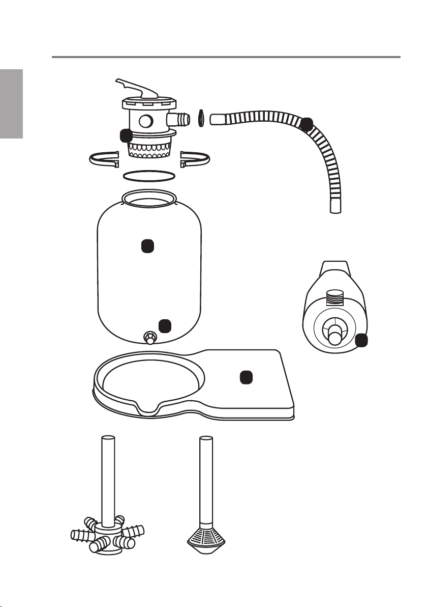
COMPONENTS OF THE FILTER SYSTEM
1. Pump
2. Filter tank
3. Drain valve
4. Filter pallet
5. Multiway valve
6. Connecting hose pump - valve
* Each delivery includes one riser
pipe model only.

Assembly and Operating Instructions Sand Filter System without Pre-lter
Important instructions
9
• The use of lter systems for swimming pools
and their protected areas is only permitted if
they are designed and constructed in accordance with VDE 0100-49D. It is mandatory to
protect the power connection via an residual
leakage circuit breaker.
• In order to maintain the required protected
area (removal of electronic equipment from
water), the lter system must be positioned
outside the water with a minimum distance
of 3 m. (Protected area 2 according to VDE
0100-702.)
• Further safety instructions can be found in
the enclosed operating instructions for the
pump. These must be observed! (The CE
label is also included).
TABLE OF CONTENTS
1. Filter system – Description
1.1 Description of 6-way valve
1.2 Description of circulation pump
1.3 Description of lter tank
2. Commissioning
2.1 Assembly Instructions - Assembly
2.2 Filling the quartz sand lter
2.3 Filling water in - Commissioning
2.4 Flushing the quartz sand
2.5 Filter – Operation
2.6 Setting the ltration time
2.7 Connection of sand lter system
3. Regular backwash
3.1 Backwash
3.2 Rinse
4 Maintenance works
4.1 Maintenance of lter tank
4.2 Maintenance of circulation pump
4.3 General maintenance
To avoid damage:
English
• Never let the pump run dry (the lter system
must be installed and the suction hose
lled with water before commissioning).
The connection to the pool skimmer and to
the inlet nozzle must be completed before
commissioning.
• Actuate the 6-way valve only when the pump
is switched off!
• Filter systems with non-self-priming pump
must be installed below the water level.
5 Taking out of operation
6. Troubleshooting
6.1 Pump not priming
6.2 Insufcient performance of circulation pump
6.3 Circulation pump is too noisy
6.4 Circulation pump does not start automatically
6.5 Circulation pump leaks
6.6 Sand in the pool
6.7 Filter pressure is not correct
6.8 Water is not clear
6.9 Pool loses water
7. Water treatment –
General Information
7.1 pH value
7.2 Algae control
7.3 Error/fault
7.4 Continuous disinfection
7.5 Turbidity
7.6 Causes of unsatisfactory condition of water

10
Assembly and Operating Instructions Sand Filter System without Pre-lter
1. FILTER SYSTEM – DESCRIPTION
English
The sand lter system you have
purchased is a high-quality quality
product. We hope you will enjoy your
swimming pool and the lter system.
We recommend that you read these assembly
instructions and the enclosed operating instructions
for the pump carefully. Keep them in a safe place
1.1 DESCRIPTION OF 6-WAY VALVE
The individual functions/positions of the plastic
valve are clearly marked on the upper side so that
there is no risk of confusion. Please also observe
the drawings and explanations in our Quick
Start Guide on page 5.
1.1.1 FI LTER:
Filtration (operating state)
In this position, the swimming pool water is
pumped through the lter tank and quartz sand
and then back to the pool. The dirt is ltered
out via the quartz sand.
1.1.2 Closed:
Servicing
All functions are disabled in this position. The
circulation pump must not be switched on. This
position is used when maintenance works are
carried out in the lter tank.
1.1.3 Backwash:
CLEANING THE Filter system
In this position, the swimming pool water
is pumped through the lter in the opposite
direction (from bottom to top) to clean it. The
waste water is drained sideways out of the
valve (hose outlet = waste).
and familiarize yourself with the special features
and possible uses of this system. The lter system
ensures a mechanical treatment of swimming pool
water. However, an impeccable water quality can
only be guaranteed if the water is treated chemically
in addition (see information on reverse side).
1.1.4 Recirculate:
Circulate without ltration
(increased circulation)
In this position, the swimming pool water ows
right into the swimming pool, the lter tank is
bypassed. This setting is used after adding
pool chemicals (e.g. after a shock chlorinati-
on).
1.1.5 RINSE:
Filtration into the sewer
In this position, the lines of the lter system are
cleaned from residual dirt after backwashing.
1.1.6 Waste:
Emptying/Sewer
In this position, the swimming pool water is
pumped directly into the sewer (valve outlet
‚Waste‘).

Assembly and Operating Instructions Sand Filter System without Pre-lter
1.2 DESCRIPTION OF CIRCULATION PUMP
The circulation pump is used to pump the water from the swimming pool through the lter tank and back into
the swimming pool (see also enclosed separate pump manual).
1.2.2 SHAFT SEAL
The pump is equipped with a mechanical seal between the pump housing and the motor to seal the
motor shaft. This seal is a wearing part/no warranty
(see pump 4.2.3).
1.3 DESCRIPTION OF FILTER TANK
11
English
The lter tank is used to mechanically remove
suspended particles such as hair, skin akes, pollen
and other impurities from the swimming pool water
by means of a special quartz sand for swimming
pools (0.4 - 0.8 mm or other lter medium, e.g. lter
glass or lter balls). This is done at a pressure of
0.4 - 0.8 bar. When the pressure increases (loud
pumping noise) the lter must be backwashed (see
section 2.4). This is by no means a defect of the
pump, it is a normal process, as the pump has to
work against a higher resistance if the lter tank/
lter sand is too dirty. To measure the lter pressure
in the tank, there is an optional pressure gauge
(item no.: 2600020) available (not included in delivery), which is xed at the top of the valve (bleeder
screw). The pressure gauge allows you to read
the lter pressure at any time and thus determine
whether a backwashing is required. If you do not
have or use a pressure gauge, we recommend
backwashing once a week.
12
English
Assembly and Operating Instructions Sand Filter System without Pre-lter
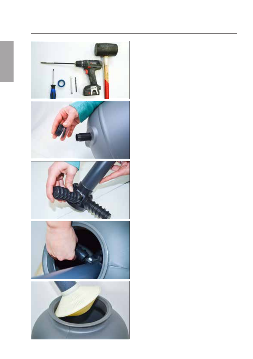
2. INSTALLATION OF SAND FILTER SYSTEM
Step 1:
The following tools are required for this: Phillips
screwdriver, Teon tape, 7 mm wrench, possibly
drill, possibly cordless screwdriver, rubber hammer.
Step 2:
Insert the drain valve into the pre-drilled hole on the
lter tank, i.e. from the inside to the outside. While
doing so, please mount a rubber seal each from the
inside and from the outside and then x the drain
valve with the lock nut from the outside.
Step 3: (Instructions for model with riser pipe 1)
At rst, screw only 2 of the lter cartridges into the
riser pipe.
Step 4: (Instructions for model with riser pipe 1)
The other lter cartridges are inserted in the tank,
as otherwise the assembled riser pipe would not t
through the tank opening.
Step 5: (Instructions for model with riser pipe 2)
If you use our alternative tank with xed (glued) lter
basket, it is simply inserted into the lter tank.

Assembly and Operating Instructions Sand Filter System without Pre-lter
Step 6:
Before lling the quartz sand in, close the top of the
riser pipe with a plastic bag to prevent sand from
entering the riser pipe.
Step 7:
Please select the correct quartz sand grain size (0.4
- 0.8 mm) for your lter system, as otherwise there
may be problems during the lter operation.
Step 8:
Carefully ll the correct amount of quartz sand (see
table) in from the top into the lter tank, and ensure
that the riser pipe remains in the correct central
position. About two-thirds of the lter tank should be
lled with quartz sand.
13
English
Step 9:
Next place the O-ring on the valve from below.
Step 10:
Please ensure that the clamping ring and the screws
are mounted/assembled correctly, i.e. in the right
direction. You can see the correct way on the photo:
The nut of the screw also
grips into the groove of
the clamping ring to hold
the nut in place.

14
English
Assembly and Operating Instructions Sand Filter System without Pre-lter
Step 11:
If necessary, loosen the clamping ring carefully
using a rubber hammer to achieve a better sealing
and a uniform tensioning of the clamping ring.
Step 12: Only with 2260140 and 2260148 pump
Insert the rubber hose tting (only included with
2260140 and 2260148 pump) into the connecting
hose and insert in on the upper pump connection
(as far as possible). Then x it rmly with a hose
clip.
Step 13:
Fasten the hose to the middle hose connection
(labeled ‚Pump‘) on the top of the valve.
Step 14:
Fix the lter pump on the lter pallet using the
self-tapping screws.
Step 15:
If the hose connections do not seal well, you can
use Teon tape for additional sealing. To do this,
wrap at least 15 times.

Assembly and Operating Instructions Sand Filter System without Pre-lter
Step 16:
The hose is attached to the suction side of the
pump, which runs to the swimming pool skimmer.
Step 17:
The return hose to the inlet nozzle is connected to
the ‚Return‘ hose connection via the valve.
Step 18:
On the right-hand side of the valve, you can nd the
hose connection for backwashing (dirty water into
the drains). This is labeled ‚Waste‘.
15
English
2.3 FILLING WATER IN - COMMISSIONING THE FILTER
2.3.1 INSTALLATION WITH BUILT-IN SKIMMER
After the swimming pool has been lled with
water up to at least the middle of the surface
skimmer, the water automatically runs into
the pump. If necessary, we recommend the
installation of a gate valve in addition. It can
be used to interrupt the water ow of the lter
system.
2.3.2 SYSTEM WITH SUSPENSION SKIMMER
Before the suction hose is connected to the
skimmer, it must rst be completely lled with
water.
2.3.3 FRAME POOL OR QUICK UP POOL
Please connect the suction hose and also the
return hose to the two hose ttings of the pool.
We recommend to install a suitable skimmer
offered by the pool manufacturer in addition.
This is usually connected with a separate
hose from the inside of the pool.
In no case should the 2 hoses simply hang
into the water and the lter system be installed
without a skimmer. This can and will not work
and there is a risk of irreparable damage to the
lter system/pump.

16
Assembly and Operating Instructions Sand Filter System without Pre-lter
English
2.4 RINSING THE QUARTZ SAND
(BEFORE COMMISSIONING)
Set the hand lever of the 6-way valve to the RINSE
position, switch the lter system on electrically. In
case of very long suction lines, it can take up to 2-3
minutes until the swimming pool water is pumped.
After water starts to be pumped, drain the water into
the sewage system for about 1 minute to prevent an
abrasion of quartz sand from entering the swimming
pool via the inlet nozzle. Then set the valve to
“Rinse” for 30 seconds (see also section 3.2).
Warning! Please operate the 6-way
valve only when the lter pump is
switched off.
Otherwise there is a danger of destroying
the 6-way valve!
2.5 FILTER – OPERATION
Set the hand lever of the 6-way valve to FILTER.
The quartz sand lter for a mechanical water
treatment of your swimming pool is now ready for
operation. Switch the lter system on.
2.6 SETTING THE FILTRATION TIME
The operating time of the quartz sand lter depends
on swimming pool size (water volume), bather load,
weather and the used chemicals.
Example: It is recommended to recirculate the
pool volume 1 to 1.5 times in 24 hours.
If a pool volume of 10 m³ is circulated 1.5 times, a
total of 15 m³ must be circulated. If the pump has
an output of 6 m³ per hour, the operating time of the
lter is approx. 2.5 hours. To achieve an optimal
mechanical cleaning, the lter should be running
without interruption during this time.
Attention: On hot days, the lter time must be
increased to ensure a sufcient disinfection.
(Example: 2 hours in the morning and 2 hours in the
afternoon.) The lter system must also be switched
on on rainy days, as organic impurities get into the
swimming pool via the rainwater, which promotes
algae growth!
2.7 CONNECTING THE SAND FILTER
SYSTEM TO THE POOL
A connecting hose to the skimmer of your pool
(where the dirty water is drawn in) is laid on the suc-
tion side of the pump (horizontal hose connection).
The cleaned water is fed back into the pool via a
connecting hose between the valve of your lter system (the valve has 3 black hose adapters which are
labeled as follows: Return, Waste and Pump) and
the hose adapter labeled ‘Return’.
3
RETURN
2
PUMP
WASTE
3
1
2

Assembly and Operating Instructions Sand Filter System without Pre-lter
17
3. REGULAR BACKWASHING
Clean the lter (backwashing) once a week.
To be able to determine when to carry out a lter
cleaning (BACKWAHING), we recommend to use a
pressure gauge. Systems with pressure gauge allow
reading the pressure off the gauge. If the pressure
increases by 0.3 bar (max. 0.6 bar), a backwashing
must be carried out. A weekly backwashing of
the lter is recommended, even if this value is not
reached. This ensures that the lter sand remains
loose and does not stick together. Pressure gauges
for our lter system are available separately (article
no.: 2600020). Please contact your dealer, if
required.
Attention: Rell the missing water
level in the pool with fresh water after
backwashing!
3.1 BACKWASHING
Set the 6-way valve to BACKWASH.
Switch the lter system on. When the pumped water
is clean, the backwashing process is completed,
which should take 3 minutes at the most.
Set the 6-way valve to FILTER or RINSE (switch the
power supply off rst).
3.2 RINSE
The 6-way valve optionally also allows draining
parts of the residual dirt after backwashing into the
sewer system instead of the swimming pool.
4. MAINTENANCE WORKS
4.1 MAINTENANCE OF FILTER TANK
The gate valves must be closed during mainte-
nance works and be reopened after completion of
these works.
The ll level and condition of the quartz sand must
be checked once a year. The sand must ow loosely
through the hand! If lumps are formed, the quartz
sand must be replaced completely. See Section 2.2
‘Filling’.
4.2 MAINTENANCE OF CIRCULATION PUMP
Switch the pump off, set the 6-way valve to
CLOSED. Observe point 1.1.2! In the winter, empty
the pump completely and store it in a frost-free
place; turn the motor shaft occasionally to prevent
the shaft from becoming encrusted by limescale
deposits.
4.2.1 MOUNTINGS
The two engine mounts are self-lubricating
and do not require maintenance.
4.2.2 SHAFT SEAL
The shaft is equipped with a mechanical seal
which may leak after prolonged operation. We
recommend purchasing a new pump when
this happens.
4.2.3 MOTOR
No special maintenance required.
English
To do this, set the 6-way valve to RINSE. Switch the
lter system on for a maximum of 30 seconds, then
reset the 6-way valve to FILTER.
4.2.5 MAINTENANCE OF 6-WAY VALVE
This valve is maintenance-free. It is important, however, that the pump is always rst
switched off before changing the position.

18
Assembly and Operating Instructions Sand Filter System without Pre-lter
English
4.3 GENERAL MAINTENANCE
• The swimming pool must be maintained and
serviced in accordance with the manufacturer’s
instructions.
• The skimmer strainer in the surface skimmer
must be cleaned regularly at short intervals.
• It is important to ensure that the water level in the
pool never falls below the middle of the skimmer
at least (minimum lling level).
5. TAKING OUT OF OPERATION
• The swimming pool must be winterized in accord-
ance with the relevant instructions of the pool
manufacturer.
• The lter system must be winterized if there is a
risk of frost. The following should be observed:
Drain the water from the lter tank through the
drain plug at the bottom of the lter tank.
• The pipes from and to the swimming pool must
be emptied completely.
• Switch off the power supply (set to 0), unplug the
earthed plug (Schuko).
• Remove the quartz sand from the lter tank and
store the entire lter system in a frost-protected
area (e.g. in the basement). Do not push or
transport the lled tank, otherwise there is a risk
of breakage.
6. TROUBLESHOOTING
6.1 PUMP DOES NOT DRAW IN WATER
AUTOMATICALLY OR THE PRIMING
TAKES VERY LONG
1. Check the suction line for leaks, as air is drawn in
if the line is leaking.
2. Check the water level in the pool. If the water
level in the skimmer is too low, the pump also
draws in air. Fill water in (increase water level) up
to the middle of the skimmer port.
3. Check whether the skimmer ap can be moved
easily and does no jam. Otherwise, the pump pri-
ming will be poor or the water column will always
break down. This can damage the pump.
4. Check whether the strainer basket in the skimmer
is clean, if necessary clean the strainer basket.
5. Check whether the gate valves in the suction and
pressures pipes are open.
6.2 INSUFFICIENT PERFORMANCE OF
CIRCULATION PUMP
1. Filter is dirty; it must be backwashed.
2. Gate valves in the system are not fully open.
3. Skimmer basket in skimmer dirty? Cleaning required.
4. Suction line leaking, pump draws air in.

Assembly and Operating Instructions Sand Filter System without Pre-lter
19
6.3 CIRCULATION PUMP IS TOO NOISY
1. Filter is dirty; it must be backwashed.
2. Remove foreign particles from the pump, unscrew
pump housing, clean housing and impeller.
3. Motor bearings are too noisy, replace the entire
motor complete with impeller.
4. The pump is standing on a bare wood oor or
concrete oor, resulting in a sound transmission
to the building (structure-borne sound). Place the
pump on a noise-damping insulating base (rubber,
cork, etc.).
6.4 CIRCULATION PUMP
DOES NOT START AUTOMATICALLY
1. Check whether the power line is live.
2. Check if the fuse is defective.
3. For AC pumps, check whether the capacitor is in
proper working order.
4. Check that the motor is in proper working order;
have the winding checked by an electrician.
5. Check whether the pump has got stuck (motor
shaft can be turned easily with a screwdriver, otherwise see 6.4). Attention: Carry out only after the
mains plug has been disconnected! Risk of injury!
Check whether the motor-protective circuit-breaker has been tripped; if so see point 6.2.
6.5 WATER DRIPPING FROM CIRCULATI-
ON PUMP BETWEEN PUMP HOUSING
AND MOTOR
1. During commissioning, it is possible that water
escapes in drops at intervals of approx. 2 minutes.
After a few hours of operation, when the seal has
run in, the dripping stops automatically.
2. If water is constantly leaking from this point, the
mechanical seal is defective.
6.6 QUARTZ SAND IS FLUSHED OUT OF
THE FILTER INTO THE POOL
1. Incorrect grain size (too ne). Special quartz
sand granulation 0.4 - 0.8 mm required.
2. Filter base in lter container damaged - replace
lter base.
3. 6-way valve damaged or dirty - replace/clean.
6.7 FILTER PRESSURE AT THE PRESSURE GAUGE DOES NOT DROP BACK
TO INITIAL PRESSURE AFTER BACKWASHING, OR INITIAL PRESSURE IS
TOO HIGH
1. Pressure gauge defective - replace.
2. Quartz sand hardened and/or clumped - lter sand
must be replaced.
3. Suction or pressure line too small or valve closed.
6.8 WATER IS NOT CLEAR
1. Insufcient disinfection (chlorination), which cau-
ses an overload of the lter; check and adjust
chlorine and pH value in respect of specied
values.
2. Filter is too small.
3. Circulation time is too short.
4. If necessary, use occulant for quartz sand lters.
5. Insufcient lter backwashing operations cause
short lter run times.
6.9 SWIMMING POOL LOSES WATER VIA
THE FILTER SYSTEM
1. Gaskets in 6-way valve damaged - replace.
2. Feed pipe from swimming pool is leaking.
English

20
Assembly and Operating Instructions Sand Filter System without Pre-lter
WHAT TO DO IF...?
Tips for troubleshooting in case of problems that may occur during setup:
English
Problem Description of problem Possible causes Possible remedial measures
Filter systems / Pumps Insufcient or no lter
performance
Pump does
not star t
Engine noise
but no lter
performance
Pump leaking Mechanical seal is defective Pump must be returned for repair
Sand in pool Used lter sand has
Filter tank/
pipes leaking
No water ow from pool to
lter system and back.
Air intake via suction pipe Check connection piece and seals
Mechanical seal is defective Pump must be replaced
Excessive suction lift Correct pump height or use a check
Pre-lter or skimmer without water
(level)
Filter is clogged Backwash in case of sand lter.
Diameter of suction line
too small
Pump not properly mounted Fix pump correctly
Foreign particles in the pump Clean pump
Pump impeller or
shaft is defective
Incorrect voltage Compare pump voltage with mains
Foreign particles in the pump Clean pump
Thermal protection relay has
responded
No voltage Reset the fuse
Motor is blocked Pump must be returned for repair
Foreign particles in the pump Clean pump
Motor is blocked Pump must be replaced
incorrect granulation
Multi-way valve defective Replace multiway valve
Riser pipe/lter base defective Pump must be returned for repair
Screw connections not
properly tightened (too loose)
No sealing Seal with Teon tape
Mechanical damage Replace defective parts.
Hoses on pump and valve are not
mounted/connected correctly.
on the suction side Teon tape may
possibly be missing
valve
Fill up water in pool
Clean/change system or cartridge
Convert to piping system or use larger
diameter
Pump must be replaced
voltage
Reset thermal circuit breaker and
determine cause
Observe manufacturer's instructions/
use only original lter sand
Retighten/retension screw connections
Please check again if all hoses have
been mounted correctly on valve
or pump (see pages 4 and 5 of this
manual).

Assembly and Operating Instructions Sand Filter System without Pre-lter
WARRANTY
Please note the following in case you want to assert a warranty claim:
21
• We offer a 2-year warranty for our products,
starting from the purchase of the product. During
this period, we warrant that the products delivered
by us are free from manufacturing and/or material
defects.
• Our warranty obligation shall not extend to
defects, errors or damage that are the result of
improper or violent use by the customer or third
parties who are not responsible. Furthermore, the
warranty is excluded in case of force majeure.
• In case of transport of the defective product
within the warranty period, we will bear the costs.
Outside the warranty period, the customer has to
bear the costs.
• In case of a free replacement delivery, this
does not lead to an interruption of the period of
limitation in accordance with §212 BGB (German
Civil Code).
• Furthermore, we assume no guarantee for
wearing parts, for cases of poor maintenance
and for consequential damages due to the use of
impermissible supplies.
• The same applies to non-compliance with opera-
ting or maintenance instructions, overuse/over-
To ensure a prompt, trouble-free and uncomplicated processing of your complaint, it is
important that the registration form is completely lled out in block letters and submitted
together with all required documents (proof of purchase or sales receipt/photos). A proof of
purchase like a sales receipt is a mandatory prerequisite for all warranty claims. Without proof of
purchase, it is unfortunately not possible for us to acknowledge/process a complaint. Relevant photos
regarding your complaint will help us to evaluate the facts more quickly. This will save both you and us
unnecessary costs and waiting times/delays.
straining or other interventions in the delivered
goods, in cases where modications are made
to the delivered goods, parts are replaced or
consumables are used for these products that do
not meet the original specications.
• Customer claims for damages, e.g. for non-performance, culpa in contrahendo, violation of
secondary contractual obligations, consequential
damages caused by a defect, unlawful acts and
other legal grounds are excluded. This does not
apply to the liability for lack of a guaranteed property, intent or gross negligence. In particular, no
damages are paid for water and chemicals that
had to be drained due to a leakage in your pool.
English
By post to: Waterman Customer Service
Bahnhofstr. 68, 73240 Wendlingen/Germany
By fax to: + 49 (0) 7024/4048-667
By E-mail to: service@waterman-pool.com
You can download the registration form here:
http://waterman-pool.com/#downloads

Place* Date* Signature*
I want to submit the following complaint
(Please include a precise description):
the product (model) with article number
I bought from (company) at (Postcode/Town)
*Required information/documents

processed faster and unnecessary costs and waiting times
are avoided for all involved.
It is mandatory that you attach a proof of purchase*
to your claim! (A proof of purchase like a sales receipt is
a mandatory prerequisite for all warranty claims. Without
proof of purchase, it is unfortunately not possible for us to
acknowledge/process a complaint).
Please attach relevant photos* of the damage to
your complaint! (Photos of defective item.) These allow us
to better evaluate the facts. In addition, the complaint can be
Waterman Customer Service
Bahnhofstr. 68
73240 Wendlingen/Germany
Tel.: + 49 (0) 7024/4048-666
Fax: + 49 (0) 7024/4048-667
E-mail: service@waterman-pool.com
Registration of complaint
regarding sand filter system
E-mail*
Fax
Mobile
Phone*
Postcode/City*
Address*
Name*
Your contact data

The sand lter system alone cannot ensure and provide clear swimming pool water.
The sand lter retains smallest dirt particles and removes
them from the water circulation during backwashing.
An additional treatment of the water plus disinfection, e.g. based on chlorine or oxygen,
is always required. For further information about water treatment, see here:
http://www.planet-pool.de http://www.summer-fun.info
CUSTOMER SERVICE
Thank you for purchasing one of our products.
Our products are subject to stringent nal quality
checks. It can nevertheless not be excluded that
malfunctions or defects may occur. If, contrary to
expectations, the purchased product should not
function properly or should otherwise not be in good
order, please contact our customer service directly.
As a matter of course, our customer service is
available for you also after the warranty period.
PLEASE DO
NOT RETURN TO
THE STORE!
Questions? Problems? Missing parts?
Please contact our customer hotline if you
need any help.
Waterman Customer Service
Bahnhofstr. 68, 73240 Wendlingen/Germany
Tel.: +49 (0) 7024/4048666
Fax: +49 (0) 7024/4048667
E-mail: service@waterman-pool.com
 Loading...