

Waterloo F2002 User Manual [en, de, es, fr]
OPERATOR’S MANUAL
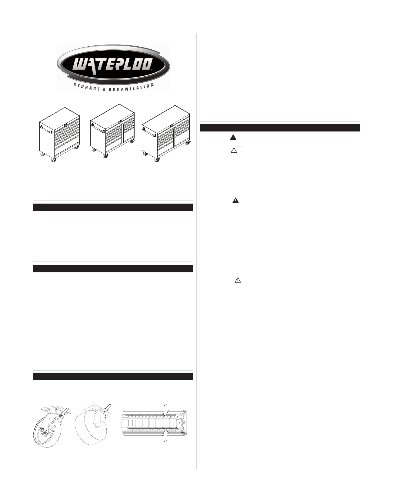
PROFESSIONAL HD 36" 8-DRAWER CABINET
PROFESSIONAL HD 46" 12-DRAWER CABINET
PROFESSIONAL HD 56" 12-DRAWER CABINET
SERVICE PARTS
IN THE UNITED STATES CALL 1-800-833-4405
FOR SERVICE PARTS. Outside the United States call your local
distributor. Please provide the Model Number when calling.
LOCATING MODEL # INFORMATION
Model numbers and other information required for service parts is
located on a label on the interior right side of the top most drawer.
CAPACITIES
• Empty weight of 36" cabinet is 308 lbs.
• Empty weight of 46" cabinet is 472 lbs.
• Empty weight of 56" cabinet is 611 lbs.
• The maximum product weight, including contents, for the 36" model
should be no more than 1800 pounds.
• The maximum product weight, including contents, for the 46" model
should be no more than 3000 pounds.
• The maximum product weight, including contents, for the 56" model
should be no more than 5400 pounds.
• The maximum weight for each 2" deep drawer is 120 lbs.
• The maximum weight for all other drawers with one set of slides is
200 lbs.
• The maximum weight for drawers with two sets of slides is 400 lbs.
• Lubricate lock and locking system components with graphite,
(yearly).
• Periodically the drawer fronts, drawer trim, and other surfaces
should be cleaned with a mild detergent and water.
• Auto wax will preserve the unit’s luster nish. Apply the wax as to
a car. The wax will also help protect the unit against scratches.
• Grease and oil can be removed with most standard cleaning
uids. For safety, use a nonammable cleaning uid.
• If drawer liners are supplied, it is recommended they are used
to protect the nish inside the drawers and to make the drawers
easier to clean. The drawer liners may be cleaned with soap and
water.
SAFETY
DANGER is used to indicate a hazardous situation which,
if not avoided, will result in serious injury or death.
WARNING indicates a hazardous situation which, if not
avoided, could result in serious injury or death.
CAUTION is used to indicate a hazardous situation which, if not
avoided, may result in minor injury, moderate injury, or property
damage.
CAUTION: Read and follow all Safety Rules and Operating
Instructions before rst use of this product.
DANGER
• DO NOT stand on this product. You may fall or cause product
to tip.
• DO NOT open more than one drawer. The product may be-
come unstable and tip.
• DO NOT step in the drawers. You may fall or cause product to
tip.
• DO NOT mount this product on a truck bed or any other moving
object.
• DO NOT move the product prior to closing and locking all the
drawers. The drawers could come open and make the product
unstable and tip.
WARNING
• WEAR SAFETY GLASSES when removing or repositioning
the slides.
• DO NOT pull this product when moving it. Push the product to
prevent personal injury.
• USE THE BRAKES when not moving this product. This will
prevent the product from rolling.
• DO NOT alter this product in any manner. For example, do not
weld external lockbars or attach electrical equipment.
• Keep the product on level surfaces. The product may become
unstable and tip if stored or moved on an uneven surface.
• BE CAREFUL when closing the cover. Remove hands before
the cover closes completely.
CAUTION
MAINTENANCE
• For casters, use high quality bearing grease, (yearly).
• Lubricate the slides with grease or equivalent,(twice yearly.)
• This product is not designed to be directly lifted with a fork lift,
or to be towed with any mechanical devices.
• The maximum weight for each drawer should never be exceeded.
• Only transport this product empty. Properly secure when
transporting.
• DO NOT exceed maximum product weight, including contents.
See Operations Sections: Capacities for more information.
USE ADEQUATE MANPOWER WHEN LIFTING OR MOV-
Ball bearing slides
Waterloo Industries, 139 West Forest Hill Avenue, Oak Creek, WI 53154, USA
ING THE CHEST OR CABINET.
F2002
HARDWARE ASSEMBLY
Hardware and other included contents can be found in the
bottom drawer (unless otherwise noted).
TOOLS REQUIRED:
3/8" Wrench 1/2" Wrench
5/16" Wrench Scissors
Screwdriver
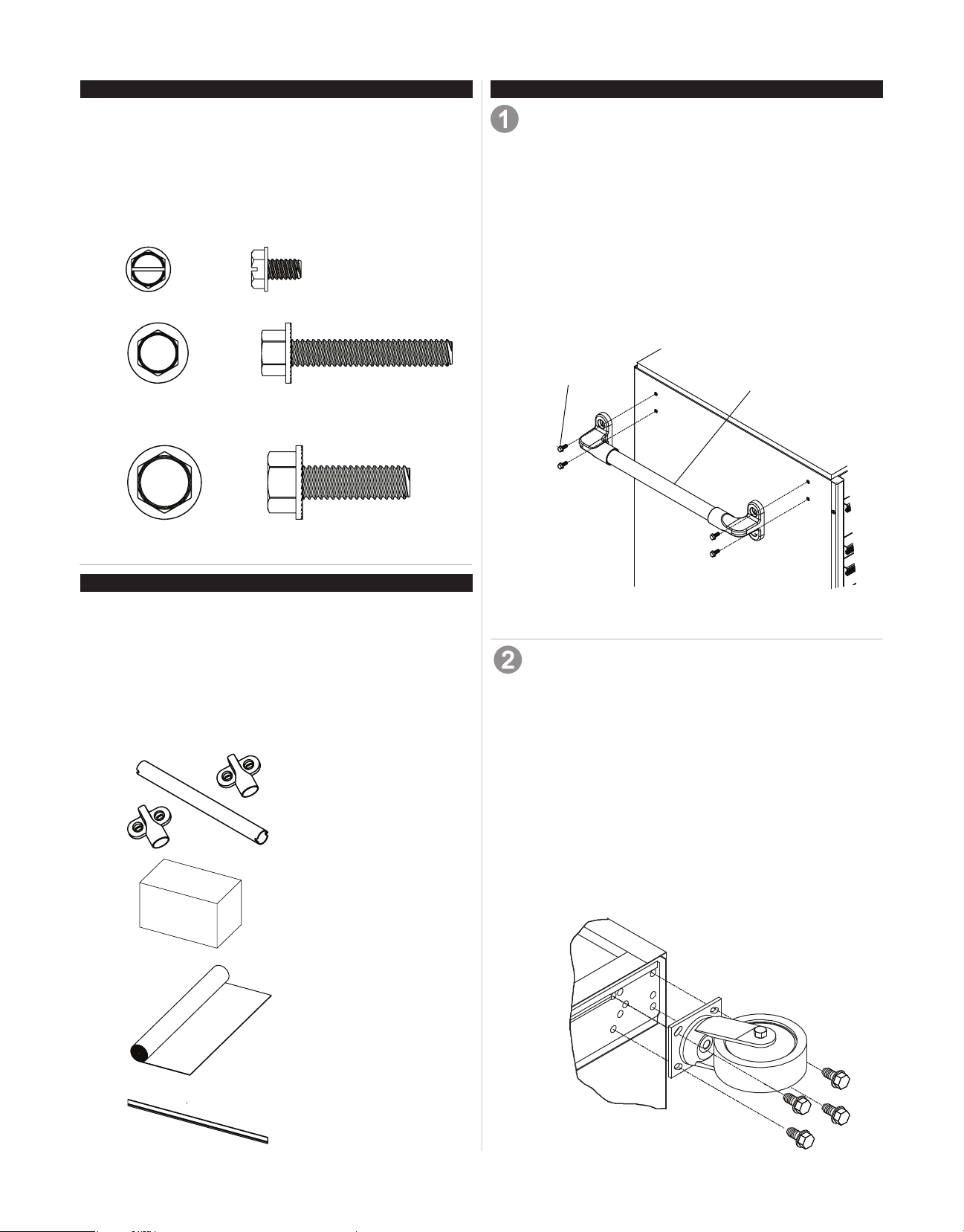
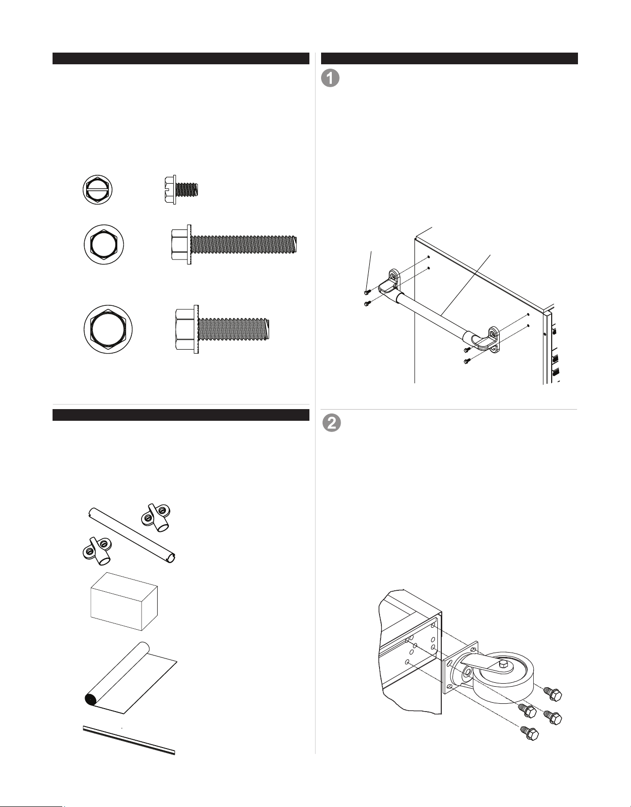
Hardware Included:
10-24 x 5/16 Hex Screw
(Qty: 24)
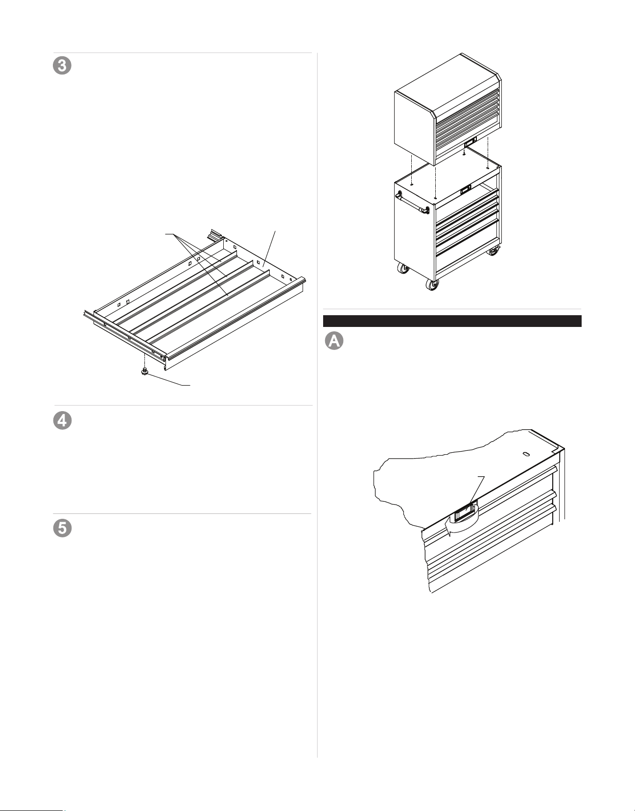
SIDE HANDLE INSTALLATION
Items Needed:
1/4 - 20 x 1-1/2" Hex Screw (Qty: 4)
Handle (Qty: 1)
3/8" Wrench
Process:
• Attach (1) handle endcap using (2) screws. Tighten with
a wrench.
• Align handle with notches in attached endcap, hold in
position.
• Align notches in second handle endcap and attach using
(2) screws. Tighten with a wrench.
• To remove, reverse the procedure.
1/4 - 20 x 1-1/2 Hex Screw (Qty: 4)
(Included with Handle Pack.)
5/16 - 18 x 1 Hex Screw (Qty: 16)
(Only included with 36" Cabinet.)
CARTON CONTENTS
Cabinet:
Handle Pack (Qty: 1)
Caster pack
Drawer Liner Roll (Qty: 1)
Drawer Dividers (Qty: 6) (for the 46" Cabinet, dividers
can be found in the top full length drawer.)
Literature
Hardware bag
Handle Pack
Caster Pack
Screw
Figure 1
CASTER INSTALLATION (if required)
Items Needed:
5/16-18 x 1 Hex Screw (Qty: 16)
Caster Pack
1/2" Wrench
Process:
• Lay the cart down on its back. (Use packaging material
to protect the paint nish.)
• Mount both swivel casters on the same side of the cart
using (4) screws on each caster.
• Wrench tighten all screws.
• Mount rigid casters to the opposite end of the cart in the
same manner.
• Return the unit to its upright position.
Handle
Drawer Liner Roll
Drawer Divider
Figure 2
2
DIVIDER INSTALLATION
Items Needed:
10-24 x 5/16 Hex Screw (Qty: 24)
Dividers (Qty: 6)
5/16" Wrench
Process:
• Decide which position and in which drawers they would
best serve your needs.
• The dividers are cut to t right to left in the drawers. If you
prefer to run them front to back, they may be trimmed in
length to do so.
• Position the dividers in the desired locations.
• Thread screws through the bottom of the drawer and into
each divider. Tighten all the screws.
Drawer
Figure 3
Dividers
Screw
DRAWER LINER INSTALLATION
Items Needed:
Drawer Liner Roll
Scissors
Process:
• Remove the non-slip drawewr liner from the roll. The
drawer liner may be cut with scissors to t each drawer
and around the drawer divideres, if necessary.
Figure 4
OPERATION
LOCKING AND UNLOCKING THE UNIT
Locking the Unit:
• Always check the unit to make sure all the drawers are
completely closed before locking.
• Pull handle lever out.
• Insert the key into the lock and turn it clockwise.
• Release lever.
Handle Lever
CHEST ATTACHMENT (if purchased)
Items Needed:
10-24 x 5/16 Hex Screw (Qty: 4)
1/2" Wrench
Process:
• Remove the wooden top from the cart.
• Remove the top two drawers of the cart (refer to the
drawer removal instructions).
• Lift the chest onto the cart. Line up the holes in the bottom of the chest with the holes in the top of the cart.
• Attach the chest using (4) screws inserted from the
underside of the top of the cart. (See Figure 8)
• Wrench tighten all screws.
• Replace the drawer (refer to drawer installation instructions).
• To remove, reverse procedure.
Figure 5
Unlocking the Unit:
• Pull the handle lever.
• Insert key into the lock and turn it counterclockwise.
• Release lever.
3
OPERATION
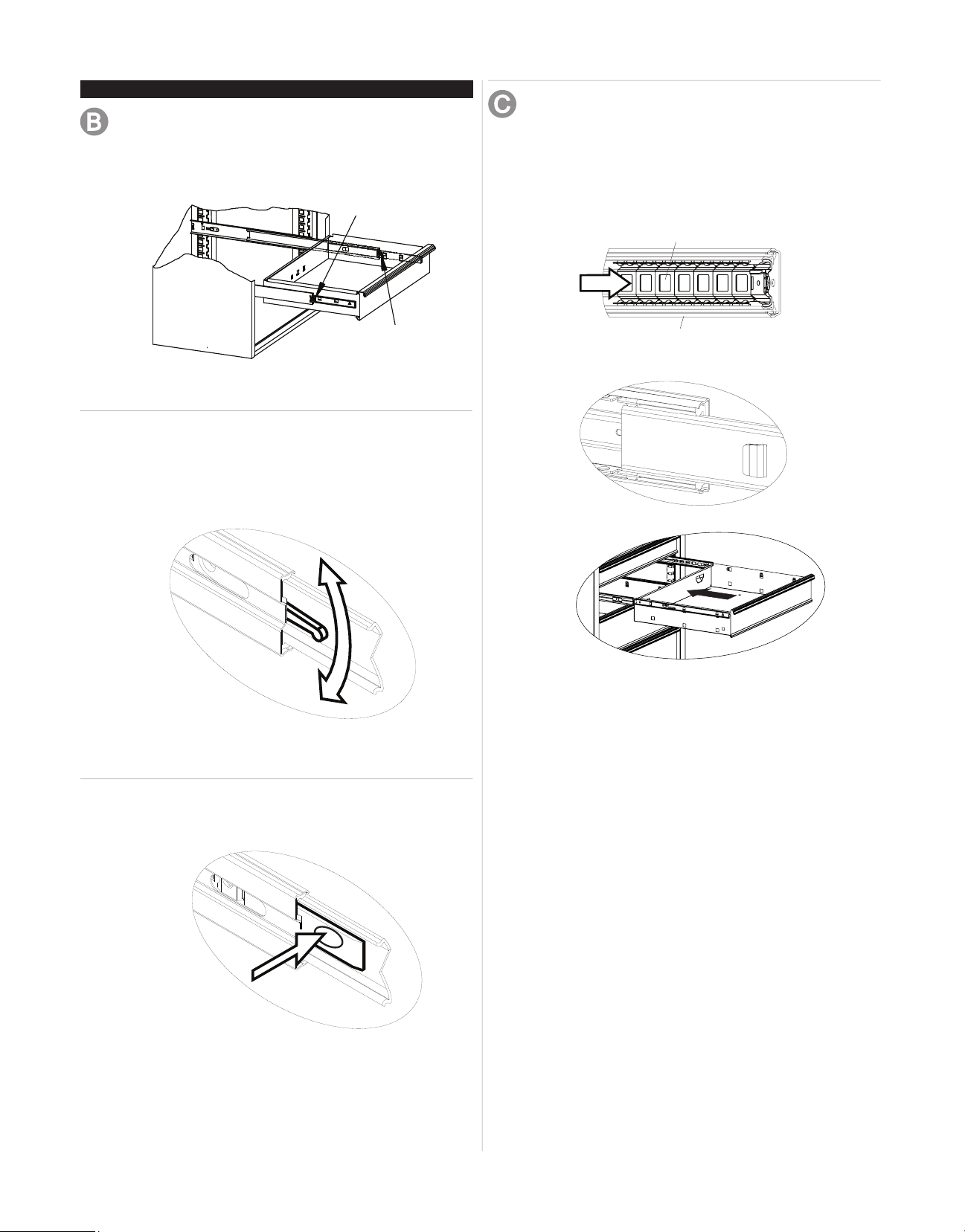
REMOVING AND INSTALLING DRAWERS
• Empty the drawer.
• Fully extend the drawer.
Release Left
REINSTALL DRAWERS
Ball bearing slide - Pull slides and slide carrier out to fully
extended position (see illustration.) Hold the slide on the
cabinet while aligning it with the slide on drawer. Slightly
insert one side and repeat for the other side. Slowly push
drawer to its fully closed position to engage slide. Open
drawer and reclose to ensure proper operation.
slide carrier
Release Right
Figure 6
BALL BEARING SLIDES
Lever Style - Lift or lower (depending on the slide) the
release lever on both sides, (this allows the slides to ride
over the stops.) Pull out to remove.
slide
Tab Style - Depress the release tabs on both sides,
(this allows the slides to ride over the stops).
Pull out to remove.
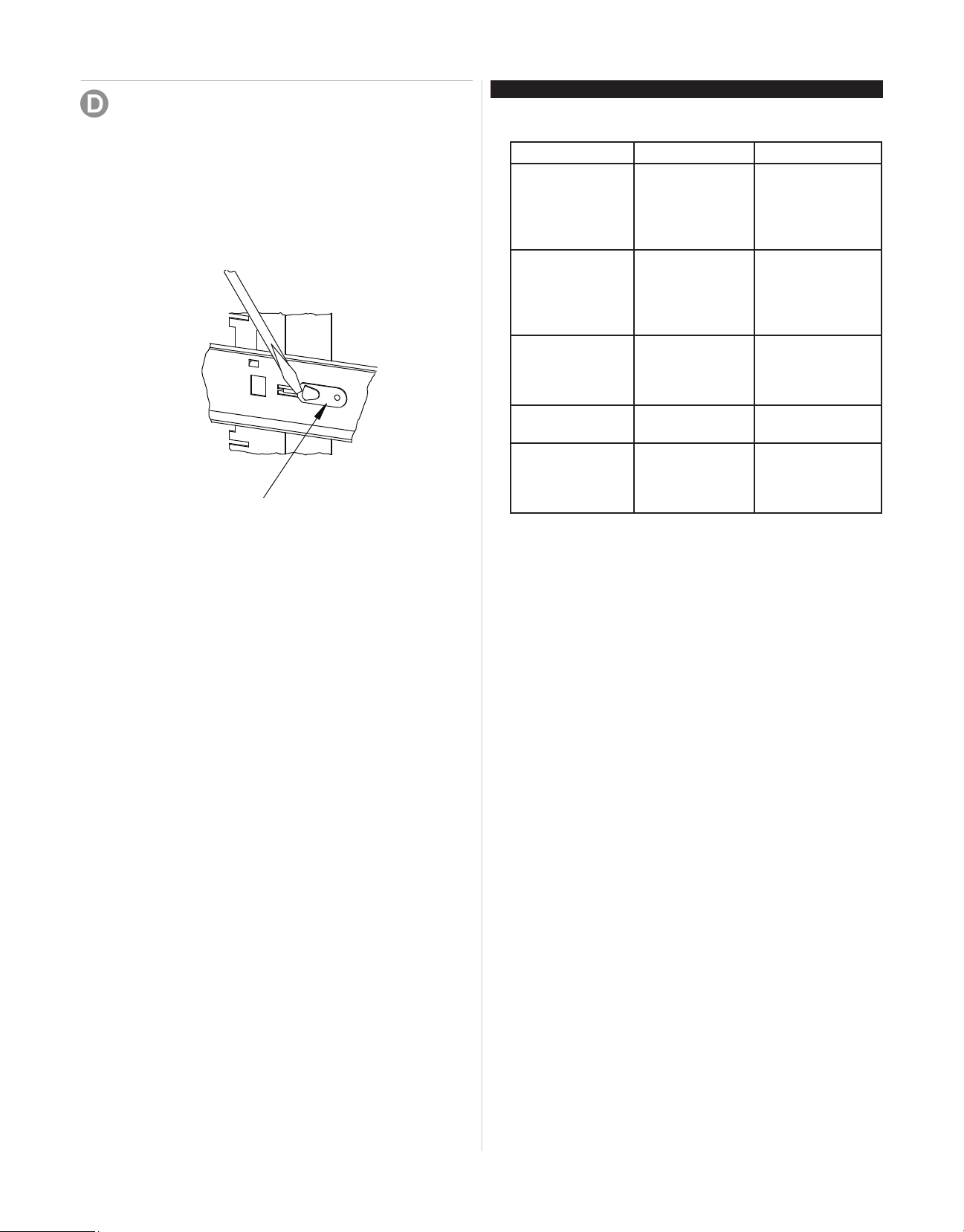
REMOVING AND INSTALLING SLIDES
Slide Removal -
• The drawers in these units can be rearranged to t your
specic needs. This means that drawers may be moved
or replaced as desired. For example, a 6-inch drawer
may be replaced by a 2-inch and a 4-inch drawer, or
three 2-inch drawers.
• First remove the drawer (Refer to Operation A).
• Lift and hold the spring retainer, and push the slide toward the rear of the unit. The slide may now be removed.
Figure 7
Spring Retainer
TROUBLESHOOTING
LOCK SYSTEM
Problem Cause Solution
The unit unlocks
but the drawers
still will not open.
The unit locks but
some drawers still
are not locked.
One or more
of the drawers
are holding the
lockbars from
releasing.
The cover on the
chest is holding
the lockbars from
releasing.
The release
cables are not
working.
The unit is leaning
too far forward.
One or more of
the drawers are
not compeletly
closed.
Completely close
all the drawers and
the lockbars will
release to open the
drawers.
Apply a downwardpressure to the
top of the cover
to let the lockbars
release.
In an UNLOCKED
position and pull
the lock lever several times.
Position the unit on
a level area.
Unlock the unit.
Close all drawers
completely. Relock
unit.
Slide Installation -
• Place the slide in the appropriate position in the unit and
pull toward the front of the unit until the spring retainer
snaps into position and secures the slide.
• For smooth operation, make sure that the drawers are
matched with their original slides.
5

MANUAL DE USUARIO
GABINETE PROFESIONAL HD DE 36IN (91,4 CM)
CON 8 CAJONES
GABINETE PROFESIONAL HD DE 46IN (116,8 CM)
CON 12 CAJONES
GABINETE PROFESIONAL HD DE 56IN (142,2 CM)
CON 12 CAJONES
PIEZAS DE SERVICIO
EN ESTADOS UNIDOS LLAME AL 1-800-833-4405 PARA
PIEZAS DE REPUESTO. FUERA DE ESTADOS UNIDOS
LLAME A SU DISTRIBUIDOR LOCAL. Suministre el número de
modelo al comunicarse.
UBICACIÓN DE INFORMACIÓN DEL NO. DE MODELO
El número de modelo y demás información requerida para las piezas de
servicio se encuentran en una etiqueta en el lado interior derecho del
cajón superior.
CAPACIDAD
• El peso vacío del gabinete de 36" (91,4 cm) es 308 lbs (139,7 Kg.)
• El peso vacío del gabinete de 46" (116,8 cm) es 472 lbs (214 Kg.)
• El peso vacío del gabinete de 56" (142,2 cm) es 611 lbs (277 Kg.)
• El peso máximo del producto, incluyendo el contenido, para el modelo
de 36" (91,4 cm) no debe ser mayor de 1800 libras (816,5 Kg.).
• El peso máximo del producto, incluyendo el contenido, para el modelo
de 46" (116,8 cm) no debe ser mayor de 3000 libras (1360,8 Kg.).
• El peso máximo del producto, incluyendo el contenido, para el modelo
de 56" (142,2 cm) no debe ser mayor de 5400 libras (2451,6 Kg.).
• El peso máximo para cada gaveta es 2” (5cm) de profundidad es 120
libras (54,4 Kg.).
• El peso máximo para los demás cajones con un par de correderas
es 200 ibras (90,7 Kg.).
• El peso máximo para cajones con dos pares de correderas es 400
libras (90,7 Kg.).
MANTENIMIENTO
• Para las ruedas, utilice grasa para rodamientos de alta calidad (anualmente).
• Lubrique las correderas con grasa o equivalente, (dos veces cada año.)
• Lubrique la cerradura y la jación de componentes de sistema con el
grato, (anualmente).
• Limpie con detergente suave y agua los frontales y los bordes laterales
de los cajones y las demás supercies.
• La cera para automóviles preservará el acabado brilloso de la unidad.
Aplique la cera como lo haría al carro. La cera también ayudará a proteger la unidad contra raspones.
• La grasa y el aceite pueden retirarse con la mayoría de los líquidos
estándar para limpieza. Por razones de seguridad, utilice un líquido
incombustible para limpieza.
• Si se suministran forros para los cajones, se recomienda que se utilicen
para proteger el acabado interno de las mismas y para facilitar la limpieza. Los forros para cajones pueden limpiarse con agua y jabón.
SEGURIDAD
PELIGRO se utiliza para indicar una situación
peligrosa que, de no evitarse, resultará en lesiones graves o la muerte.
ADVERTENCIA indica una situación peligrosa que, de no
evitarse, podría producir lesiones graves o la muerte.
PRECAUCIÓN se utiliza para indicar una situación peligrosa que, de
no evitarse, puede derivar en lesiones leves o moderadas, o en daño a la
propiedad.
ATENCIÓN: Lea y siga todas las Normas de Seguridad y las
Instrucciones de Funcionamiento antes de utilizar por primera vez este
producto.
PELIGRO
• NO se ponga de pie sobre esta unidad. Puede caerse u ocasionar que
el producto se vuelque.
• NO abra más de un cajón. El producto podría quedar inestable y vol-
carse.
• NO utilice los cajones como peldaños. Puede caerse u ocasionar que
el producto se vuelque.
• NO monte este producto en una cama de carro o ningun otro objeto
móvil.
• NO mueva la unidad antes de cerrar y asegurar todas los cajones. Los
cajones podrían abrirse y hacer que la unidad se vuelva inestable y se
vuelque.
ADVERTENCIA
• USE GAFAS DE SEGURIDAD al quitar o volver a poner las correderas.
• NO hale la unidad, empújela cuando la mueva.
• UTILICE LOS FRENOS cuando el producto no esté en movimiento Esto
impedirá que se deslice.
• NO altere la unidad en modo alguno. Por ejemplo, no suelde las barras de
sujeción externas ni le incorpore equipos eléctricos.
• Mantenga la unidad en supercies niveladas. La unidad puede tornarse
inestable y volcarse si se almacena o se moviliza en una supercie no
nivelada.
• TENGA cuidado cuando cierre la tapa. Quite las manos antes de que la
tapa cierre completamente.
PRECAUCIÓN
• Este producto no está diseñado para ser levantado directamente con un
montacargas, ni para ser remolcado con unidades mecanizadas.
• Nunca debe exceder el peso máximo de cada cajón.
• Sólo transporte esta unidad cuando esté vacía. Asegúrela adecuadamente cuando la transporte.
• NO exceda el peso máximo del producto, incluyendo el contenido. Reérase a las Capacidades para más información.
UTILICE EL PERSONAL ADECUADO PARA LEVANTAR O
MOVER EL BAÚL O EL GABINETE.
Cojinetes de bolas
F2002Waterloo Industries, 139 West Forest Hill Avenue, Oak Creek, WI 53154, USA
FERRETERÍA ENSAMBLAJE
El hardware y otros contenido incluidos pueden ser encontrados
en el Cajón inferior (a menos que se indique lo contrario).
HERRAMIENTAS NECESARIAS:
Llave Inglesa de 3/8" Llave Inglesa de 5/16"
Llave Inglesa de 1/2" Tijeras
Destornillador
FERRETERIA INCLUIDAS:
Tornillo Hexagonal de 10-24
x 5/16 (Cant: 24)
INSTALACIÓN DE LA MANIJA LATERAL
Elementos necesarios:
Tornillo Hexagonal de 1/4-20 X 1 1/2 (Cant.: 4)
Manija (Cant.: 1)
Llave Inglesa de 3/8"
Proceso:
• Fije (1) remate terminal de manija utilizando (2) tornillos.
• Apriete con una llave.
• Alinee la manija con las muescas en el remate terminal, sosténgala en posición.
• Alinee las muescas en el remate terminal de la segunda manija
y je utilizando (2) tornillos. Apriete con una llave.
• Para quitarlo, deshaga los pasos anteriores.
Tornillo Hexagonal de 1/4 - 20 x 1-1/2 (Cant: 4)
(Incluido con el paquete de la minija.)
Tornillo Hexagonal de 5/16 - 18 x 1 (Cant: 16)
(Sólo incluido con el gabinete de 36" (91,4 cm).)
CONTENIDO DE LA CAJA DE CARTÓN
Paquete de manija (Cant.: 1)
Paquete de ruedas
Rollo de forro para cajón (Cant.: 1)
Divisores de cajón (Cant.: 6) (Para los gabinetes de 46” (116,8
cm) puede encontrar divisores de gabinete en la cajón superior
de largo total.)
Bolsa de accesorios
Material impreso
Paquete de manija
Paquete de ruedas
Tornillo
Figura 1
Manija
COLOCACIÓN DE LAS RUEDAS (SI FUESE NECESARIO)
Elementos necesarios: (si fuese necesario)
Tornillo hexagonal de 5/16-18 x 1 (Cant.: 16)
Paquete de ruedas
Llave Inglesa de 1/2"
Proceso:
• Quite el cajón inferior. (Ver la Sección de Operación B.)
• Recueste la unidad rodante sobre su parte posterior. (Utilice el
material de empaque para proteger el acabado de la pintura.)
• Monte ambas ruedas giratorias en el mismo lado de la unidad
rodante utilizando (4) tornillos en cada rueda.
• Apriete todos los tornillos con una llave.
• Monte ruedas rígidas en el lado opuesto de la unidad rodante
de la misma forma.
• Vuelva a colocar la unidad en su posición vertical.
• Vuelva a colocar los cajones. (Ver la Sección de Operación C.)
Rollo de forro para cajón
Divisor de cajones
Figura 2
2
2
 Loading...