

Waterloo F1878 User Manual [en, de, es, fr]
OPERATOR’S MANUAL
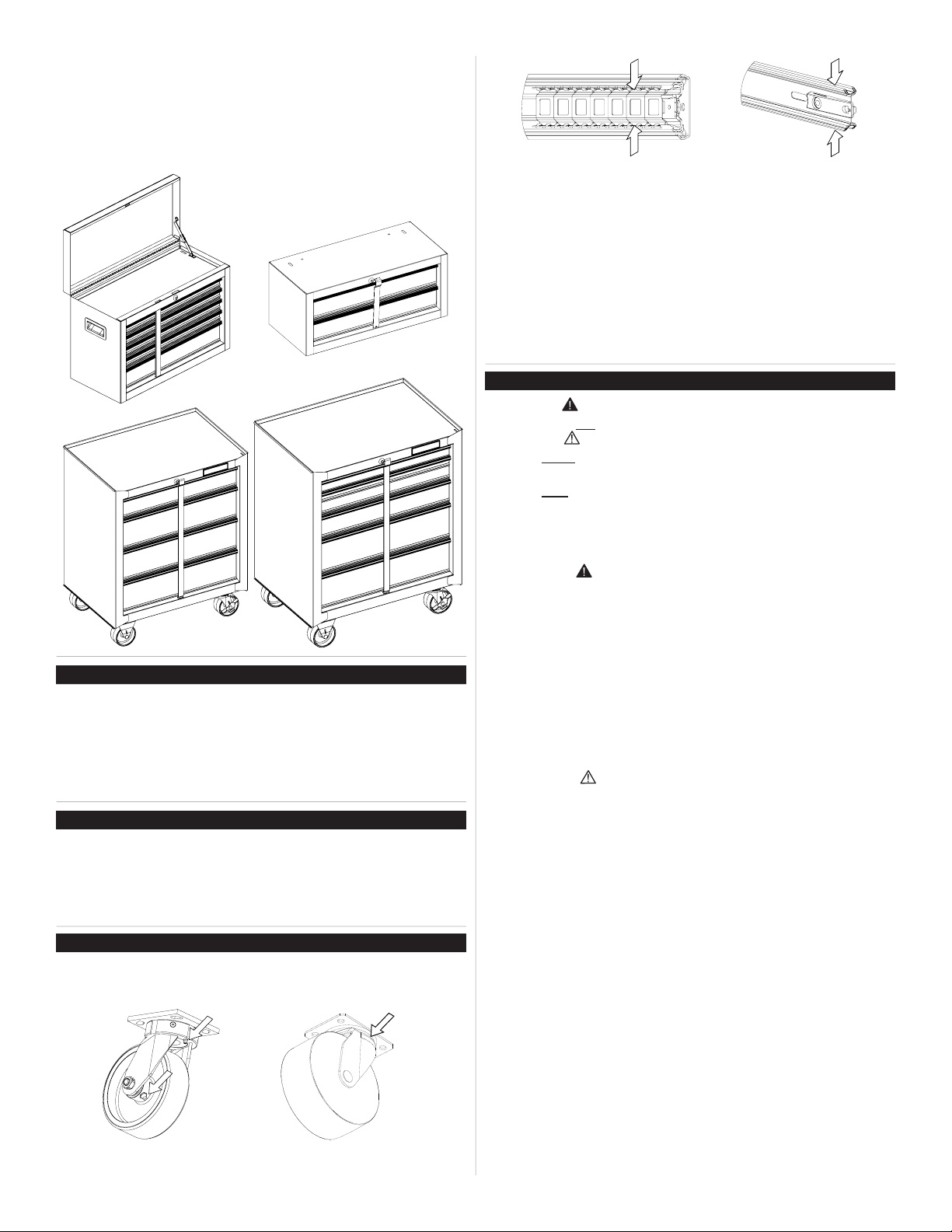
BASIC FRICTION OR BALL BEARING
CHESTS AND CABINETS
Some instructions and drawings may not apply
to your specic unit.
SERVICE PARTS
CALL 1-800-833-4405 FOR SERVICE PARTS. Refer to Service
Parts Drawing for full listing of Service Parts. Please have model
number ready at time of call.
LOCATING MODEL # INFORMATION
Model number and other information required for service parts is
on a label located on the back of the unit.
CAPACITIES
• The maximum weight for each drawer should be no more than
25 pounds.
• The maximum product weight, including contents, should be no
more than 500 pounds for cabinets; maximum including contents, 300 pounds for tool centers.
MAINTENANCE
• For casters, use high quality bearing grease (yearly).
• Lubricate the slides with grease or equivalent (twice yearly.)
Ball bearing slides
• Periodically the drawer fronts, drawer trim, and other surfaces
should be cleaned with a mild detergent and water.
• Auto wax will preserve the unit’s luster nish. Apply the wax as to
a car. The wax will also help protect the unit against scratches.
• Grease and oil can be removed with most standard cleaning
uids. For safety, use a nonammable cleaning uid.
• If drawer liners are supplied, it is recommended they are used
to protect the nish inside the drawers and to make the drawers
easier to clean. The drawer liners may be cleaned with soap and
water.
Friction slides
SAFETY
DANGER is used to indicate a hazardous situation which,
if not avoided, will result in serious injury or death.
WARNING indicates a hazardous situation which, if not
avoided, could result in serious injury or death.
CAUTION is used to indicate a hazardous situation which, if not
avoided, may result in minor injury, moderate injury, or property
damage.
CAUTION: Read and follow all Safety Rules and Operating
Instructions before rst use of this product.
DANGER
• DO NOT stand on this product. You may fall or cause product to
tip.
• DO NOT open more than one drawer at a time. The product may
become unstable and tip.
• DO NOT step in the drawers. You may fall or cause product to
tip.
• DO NOT mount this product on a truck bed or any other moving
object.
• DO NOT move the product prior to closing and locking all the
drawers. The drawers could come open and make the product
unstable and tip.
WARNING
• WEAR SAFETY GLASSES when removing or repositioning the
slides.
• DO NOT pull this product when moving it. Push the product to
prevent personal injury.
• USE THE BRAKES when not moving this product. This will
prevent the product from rolling.
• DO NOT alter this product in any manner. For example, do not
weld external lockbars or attach electrical equipment.
• Keep the product on level surfaces. The product may become
unstable and tip if stored or moved on an uneven surface.
• BE CAREFUL when closing the cover. Remove hands before
the cover closes completely.
• Lubricate lock with graphite (yearly).
Waterloo Industries, 139 West Forest Hill Avenue, Oak Creek, WI 53154, USA
CAUTION
• This product is not designed to be directly lifted with a fork lift, or
to be towed with any mechanical devices.
• The maximum weight for each drawer should never be exceeded.
• Only transport this product empty. Properly secure when transporting.
• DO NOT exceed maximum product weight, including contents.
See Capacities section for load rating.
F1878
HARDWARE
Tools Required:
3/8 inch wrench Screwdriver
7/16-in wrench 5/16-inch drill bit
CHEST HARDWARE INCLUDED:
1/4 - 20 x 5/8" Screw (Qty: 4)
CARTON CONTENTS
Hardware bag
Caster Pack
Literature
ASSEMBLY
NOTE: Not all assembly instructions will apply to your
model.
WARNING
Remove wooden work surface or rubber mat, if any,
before attaching chest(s) to the cabinet.
1/4 - 20 Nut (Qty: 4)
INTERMEDIATE CHEST HARDWARE INCLUDED:
1/4 - 20 x 5/8" Screw (Qty: 4)
1/4 - 20 Nut (Qty: 4)
CABINET HARDWARE INCLUDED:
1/4 - 20 x 5/8" Screw (Qty: 16)
1/4 - 20 Nut (Qty: 16)
TO ATTACH CHEST
Process:
· Remove enough drawers to access the top and bottom
mounting surfaces of the units. Refer to drawer removal
instructions.
· Place the chest in the desired location on top of the cabi-
net or intermediate chest and mark the mounting hole
locations onto the cabinet top.
· Remove the chest and drill two 5/16" (8mm) holes
through the top of the cabinet or intermediate chest.
· Secure the units together using two 1/4 - 20 x 5/8"
screws and nuts at each joint. The hardware is provided
in the bag located in the top tray of the chest.
CASTER INSTALLATION
Items Needed:
1/4 - 20 x 5/8" Screw (Qty: 16)
1/4 - 20 Nut (Qty: 16)
7/16-in Wrench
3/8-in Wrench
Process:
• Remove bottom drawers. (See Operation Section, Part
B.)
• Lay the cabinet on its back. Use packaging material to
protect the nish.
• Mount both swivel casters on the same side of the unit
as the side handle.
• Attach the casters using (4) 1/4 - 20 x 5/8" screws and
(4) 1/4 - 20 nuts per caster.
• Wrench tighten all screws. It is recommended not to
exceed 80 inch pounds of torque.
• Return the unit to its upright position.
• Reinstall bottom drawers.
Nut
Screw
2
OPERATION
NOTE: Not all operation instructions will relate to your
model.
TO LOCK CHEST
Process:
▪ Make sure drawers are fully closed.
▪ Insert the lockbar (which stores in the top tray), tabbed
end up, into the slot in the top tray and down into the slot
in the base.
▪ Close the cover and lock with the key.
TO UNLOCK CHEST
• Reverse above procedure.
TO LOCK INTERMEDIATE CHEST
The lockbar for the intermediate chest is stored in the
top drawer.
Process:
▪ Insert the lockbar into the slot in the base.
▪ Move the lockbar toward the unit until the bent end ts
into the slot near the lock.
▪ Lock with the key.
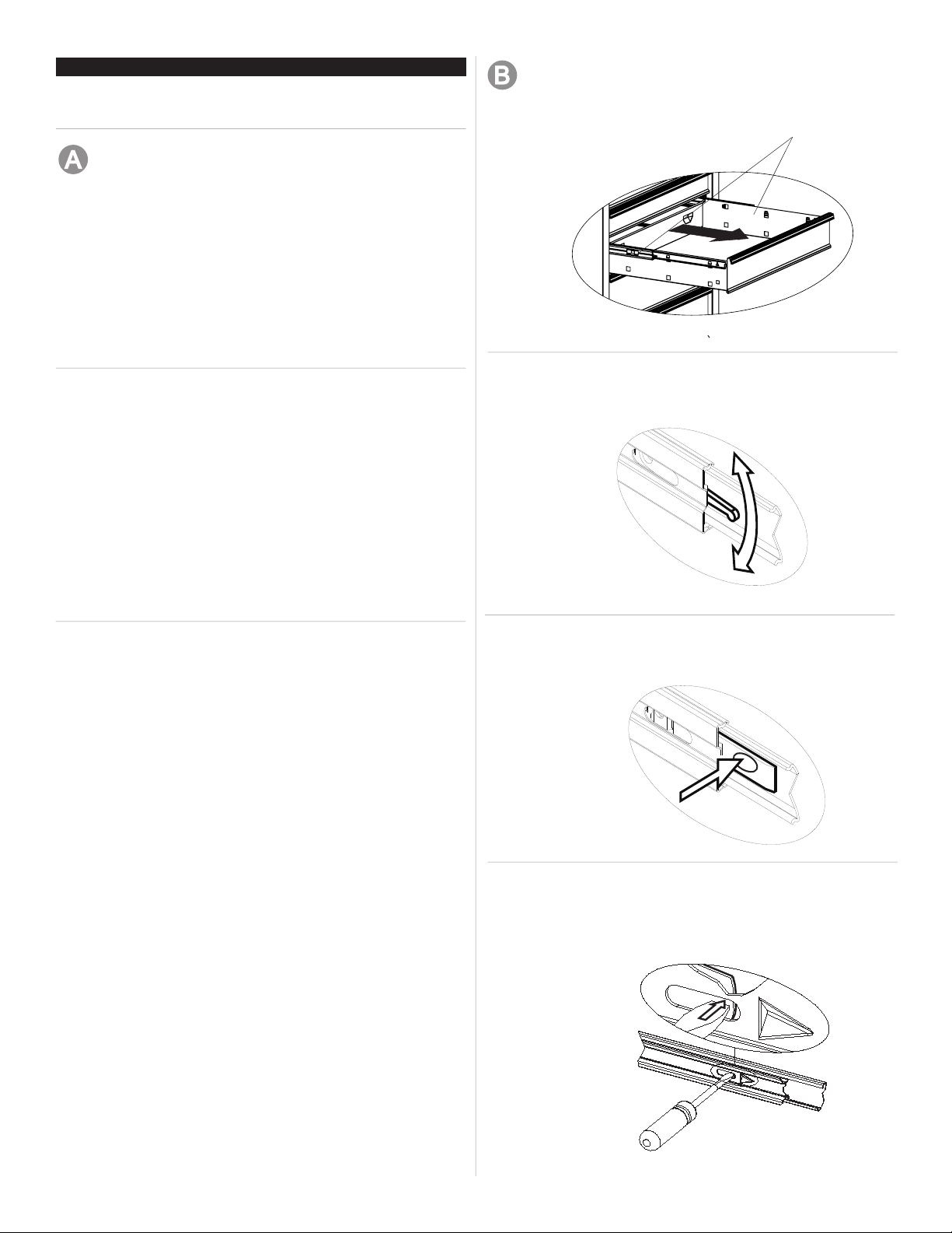
REMOVING DRAWERS
• Empty the drawer.
• Fully extend the drawer.
Release
Lever Style - Lift or lower (depending on the slide) the
release lever on both sides, (this allows the slides to ride
over the stops.) Pull out to remove.
TO UNLOCK INTERMEDIATE CHEST
▪ Reverse above procedure.
THE LOCKBAR FOR THE ROLLER CABINET IS
STORED IN A SLOT IN THE TOP FRONT CORNER OF
THE UNIT.
TO LOCK ROLLER CABINET
Process:
▪ Insert the straight end of the lockbar into the slot in the
base.
▪ Move the lockbar toward the unit until the bent end ts
into the slot near the lock.
▪ Lock with the key.
TO UNLOCK ROLLER CABINET
▪ Reverse above procedure.
NOTE: If your unit is equipped with a storage compartment
with a panel at the bottom, pull panel out, lift up and push
panel back into unit to gain access to compartment.
Tab Style - Depress the release tabs on both sides,
(this allows the slides to ride over the stops.)
Pull out to remove.
Friction Style - Fully extend the drawer. Insert screwdriver
into the slot in the side and push in on the stop until it
clears the lance. Pull drawer just past lance before
releasing stop. Repeat the process for the other slide.
3
OPERATION
INSTALLING DRAWERS
Ball bearing slide - Pull slides and slide carrier out to fully
extended position (see illustration.) Hold the slide on the
cabinet while aligning it with the slide on drawer. Slightly
insert one side and repeat for the other side. Slowly push
drawer to its fully closed position to engage slide. Open
drawer and reclose to ensure proper operation.
slide carrier
slide
Snap-In Style -
• First remove the drawer. (See section B.)
To remove the slide:
• Insert at tip screw driver between slide and unit, behind
rear rectangular cutout.(See illustration.)
• Rotate screw driver ¼ turn to force slide away from unit.
• Push on front of slide pushing it towards back of the unit.
To attach the slide:
• Locate lances within respective cutout in carrier.
• Pull slide forward until slide locks back into place.
• Reinstall drawer following drawer installation procedure.
(See section C.)
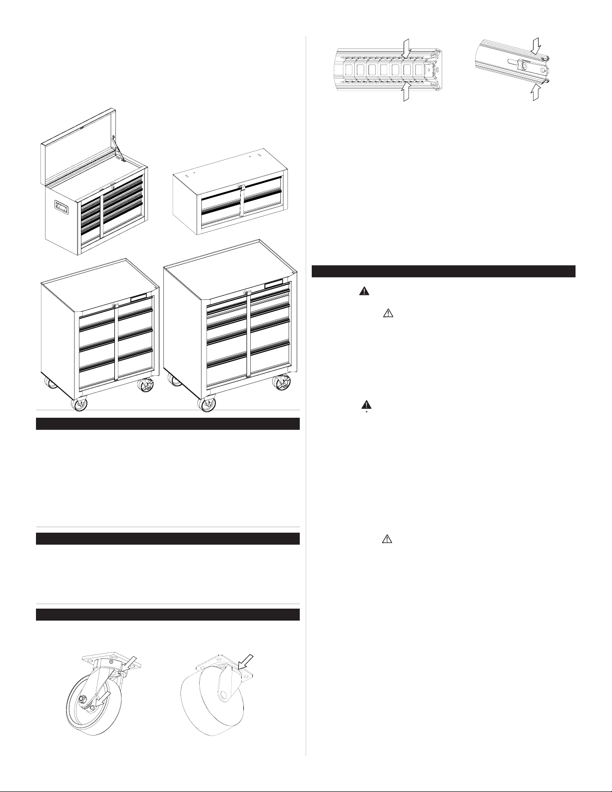
REMOVING AND INSTALLING SLIDES
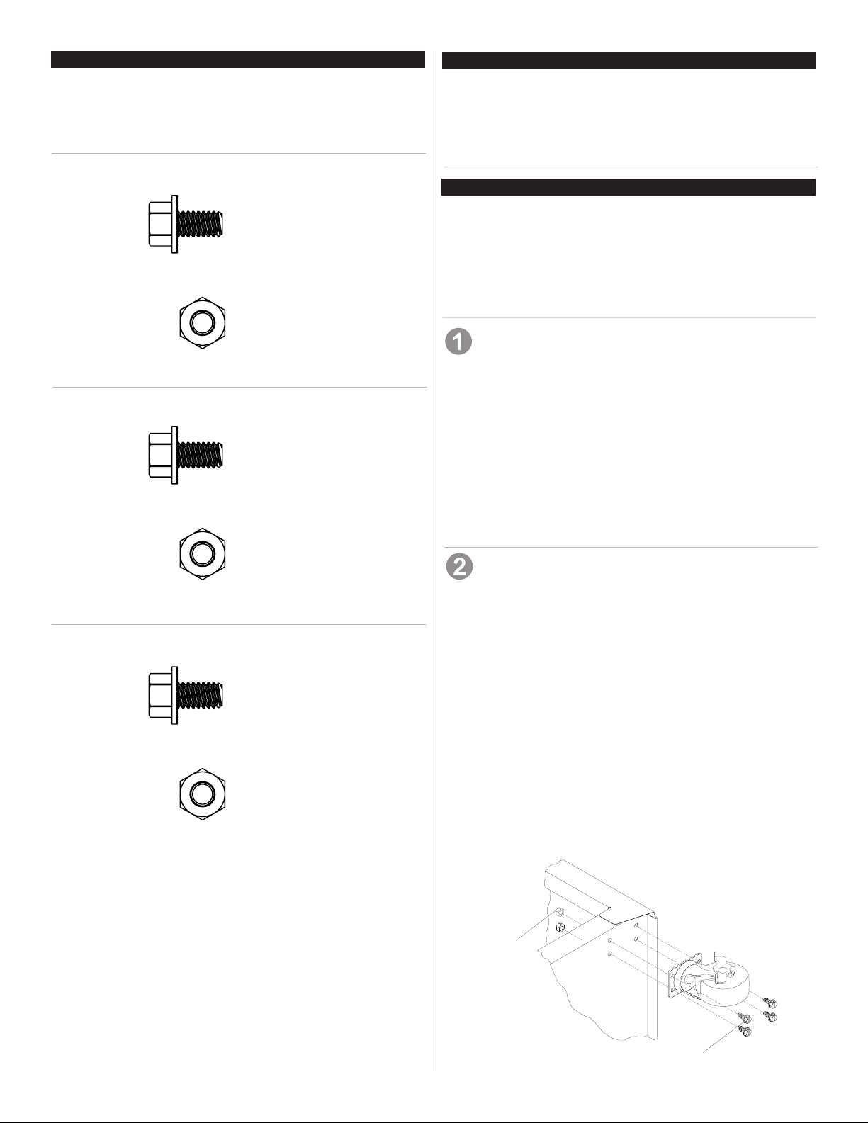
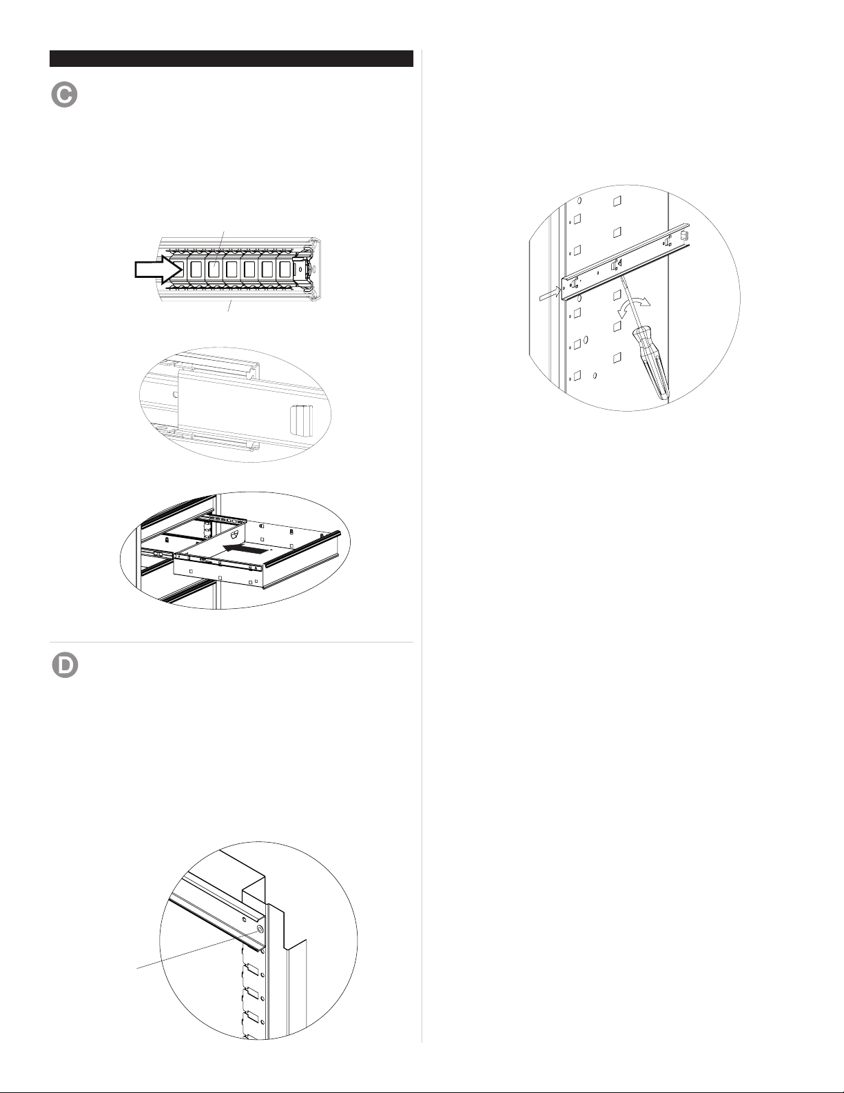
Rivet Style -
• To remove the slide from the unit, rst remove the
drawer.
• After removing the drawers drill out the rivets, use a
5/32-in drill bit. The rivets will need to be replaced.
• To reinstall the slide, place the slide in the appropriate
position in the unit and pull toward the front of the unit.
Replace rivets to secure slide to the unit.
• For smooth operation, make sure the drawers are
matched with their original slides.
Drill out rivet
4
MANUAL DE USUARIO
COFRES Y GABINETES DE FRICCIÓN BÁSICA O CON
COJINETES DE BOLA
Algunas instrucciones y dibujos pueden no aplicarse
a tu unidad especíca.
Cojinetes de bolas
• Lubrique la cerradura con grato (anualmente).
• Limpie con detergente suave y agua los frontales y los bordes laterales
de los cajones y las demás supercies.
• La cera para automóviles preservará el acabado brilloso de la unidad.
Aplique la cera como lo haría al carro. La cera también ayudará a proteger la unidad contra raspones.
• La grasa y el aceite pueden retirarse con la mayoría de los líquidos
estándar para limpieza. Por razones de seguridad, utilice un líquido
incombustible para limpieza.
• Si se suministran forros para las gavetas, se recomienda que se utilicen
para proteger el acabado interno de las mismas y para facilitar la limpieza. Los forros para gavetas pueden limpiarse con agua y jabón.
Correderas de friccion
SEGURIDAD
PELIGRO se utiliza para indicar una situación peligrosa que, de
no evitarse, resultará en lesiones graves o la muerte.
ADVERTENCIA indica una situación peligrosa que, de no
evitarse, podría producir lesiones graves o la muerte.
PRECAUCIÓN se utiliza para indicar una situación peligrosa que, de
no evitarse, puede derivar en lesiones leves o moderadas, o en daño a la
propiedad.
PIEZAS DE SERVICIO
EN ESTADOS UNIDOS LLAME AL 1-800-833-4405 PARA
PIEZAS DE REPUESTO. FUERA DE ESTADOS UNIDOS
LLAME A SU DISTRIBUIDOR LOCAL. Suministre el número de
modelo al comunicarse.
UBICACIÓN DE INFORMACIÓN DEL NO. DE MODELO
Los número de modelo y la otra información necesaria para obtener partes de repuesto, se encuentran al dorso del gabinete.
CAPACIDAD
• El peso máximo en cada gaveta no debe ser mayor de 11,4 kg. (25
pounds)
• El peso máximo del producto, incluyendo el contenido, no debe ser más
de 500 lb para los gabinetes; como máximo incluyendo el contenido, de
300 libras para los centros de herramientas.
MANTENIMIENTO
• Para las ruedas, utilice grasa para rodamientos de alta calidad (anualmente).
ATENCIÓN: Lea y siga todas las Normas de Seguridad y las Instruccio-
nes de Funcionamiento antes de utilizar por primera vez este producto.
PELIGRO
• NO se ponga de pie sobre esta unidad. Puede caerse u ocasionar que
el producto se vuelque.
• NO abrir más de un cajón a la vez. El producto podría quedar inestable
y volcarse.
• NO utilice las gavetas como peldaños. Puede caerse u ocasionar que
el producto se vuelque.
• NO monte este producto en una cama de carro o ninguÌn otro objeto
móvil.
• NO mueva la unidad antes de cerrar y asegurar todas las gavetas. Las
gavetas podrían abrirse y hacer que la unidad se vuelva inestable y se
vuelque.
ADVERTENCIA
• USE GAFAS DE SEGURIDAD al quitar o volver a poner las corred-
eras.
• NO hale la unidad, empújela cuando la mueva.
• UTILICE LOS FRENOS cuando el producto no esté en movimiento. Esto
impedirá que se deslice.
• NO altere la unidad en modo alguno. Por ejemplo, no suelde las barras
de sujeción externas ni le incorpore equipos eléctricos.
• Mantenga la unidad en supercies niveladas. La unidad puede tornarse
inestable y volcarse si se almacena o se moviliza en una supercie no
nivelada.
• TENGA cuidado cuando cierre la tapa. Quite las manos antes de que la
tapa cierre completamente.
• Lubrique las guías con grasa o equivalente (dos veces por año).
Waterloo Industries, 139 West Forest Hill Avenue, Oak Creek, WI 53154, USA
PRECAUCIÓN
• Este producto no está diseñado para ser levantado directamente con un
montacargas, ni para ser remolcado con unidades mecanizadas.
• Nunca debe exceder el peso máximo de cada gaveta.
• Sólo transporte esta unidad cuando esté vacía. Asegúrela adecuadamente cuando la transporte.
• NO exceda el peso máximo del producto, incluyendo el contenido. Ver la
Sección de Capacidades para capacidad de carga.
F1878
 Loading...