

Waterline Technology HFC-1000, SF-1000, SK-100 Installation And Operation Manual
DDrriinnkkiinngg WWaatteerr SSyysstteemmss
IInnssttaallllaattiioonn aanndd OOppeerraattiioonnss GGuuiiddee
Thank you for choosing AlwaysFresh™
Water the Way you Want It!™
Your AlwaysFresh Drinking Water System will provide delicious tasting,
crystal clear water directly from the selected tap… water that’s great for
drinking, cooking, hot or cold beverages, rinsing fruits and vegetables,
and conveniently connects to your ice maker, instant hot tap, chiller or
built in coffee maker.
The HFC-1000 is certified for 1.5 gpm flow and currently the only
point of use drinking water system NSF/ ANSI standard 42/53
certified for Volatile Organic Chemical, and MTBE at this flow rate.
Most systems have to reduce the flow to 1/2 gpm to achieve similar performance. Now you can enjoy high flow and chemical reduction with
one system!
High flow rates are convenient as well as efficient. Connecting the
system to the existing cold water supply to the sink eliminates the
need (most of the time) for a separate dispensing tap. When con-
nected to the existing cold water faucet in your kitchen or at your bathroom sink, your family members are using filtered water for the
benefits of a more healthy lifestyle. The amount of filtered water used
for other purposes in the kitchen ie, dishwashing, hand washing is minimal and the design allows you to use the water freely and still maintain an annual cartridge maintenance interval for most homes.
AlwaysFresh uses exclusive carbon block technology:
Superior Chemical reduction and fine filtration are combined to
produce high quality drinking water with high flow rates. With the
surface area for adsorption and filtration of up to 3x the carbon
filtration area (of comparable size units) Alwaysfresh combines high
capacity, 1/2 micron fine filtration carbon block wrapped with a
5 micron prefilter, and as well as an silver zeolite technology for filter
protection & optimizing efficacy and longevity. It also includes a hard
water scale control system* that protects your water using appliances
that heat, chill or freeze water. Scale control will extend the life of these
water using appliances and the exclusive carbon block technology will
produce a superior quality of drinking water for your family.
All AlwaysFresh Drinking Water Systems must be maintained according
to the manufacturer’s instructions, including timely replacement of the
filter cartridge.
Do not use with water that is microbiologically unsafe, or of unknown
quality, without adequate disinfection before or after the system.
Systems certified for cysts reduction may be used on disinfected waters
that may contain filterable cysts.
Check for compliance with state and local laws and regulations.
Note: Some states require installation by licensed installers, and some
states prohibit the use of saddle valves.
Note: Claims of capacity or rated service cycle are not applicable for
mechanical filtration units because of broad variations in quality and
quantity of particulate matter found in drinking water.
All of the contaminants and other substances reduced by your system are not necessarily
in your drinking water. However, the system can reduce chlorine taste and odors, as well
as cysts and other particulates 1/2 micron(1/50,000 of an inch) and larger.
HFC-1000 conforms to NSF/ANSI 53 FOR VOC reduction. See performance data sheet for
individual contaminant and reduction claims.
These systems must be maintained according to the manufacturer’s instructions, including replacement of cartridge.
*Claim not certified for scale control
The Owner’s Guide is Applicable for the
following Model Numbers:
HFC-1000............................DWS Rated capacity: 500 gallons
SF-1000................................DWS Rated capacity: 1000 gallons
SK-100..................................DWS Rated capacity: 100 gallons
For optimum performance cartridge replacement is required once
per year or sooner if the flow rate becomes too slow or if capacity
is reached whichever occurs first!
Replacement components:
RC HFC-1000 RC SF-1000
INSTALLATION OF YOUR SYSTEM
It is important that the installation be clean and sanitary. It is
recommended that all water contact parts, fittings, tubing, faucet,
etc. … be immersed in disinfectant (a capful of laundry bleach per
gallon of water), at the start of the installation.
Most systems have the mounting bracket attached to the filter head
assembly to insure that the inlet and outlet fittings are always in the
same position. Reversing this mounting bracket could result in system being installed backwards and thereby reduce its usable life.
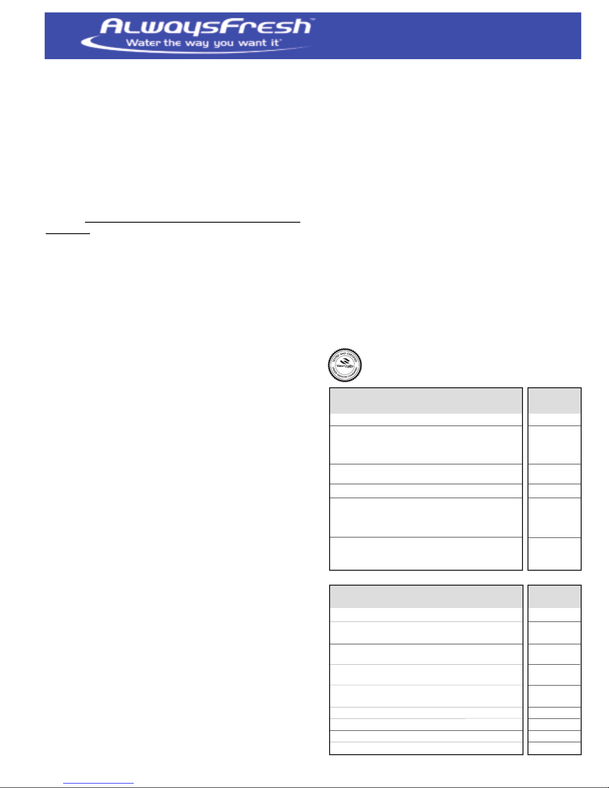
These systems conform to NSF/ANSI 42
and 53 for specific performance as
verified and substantiated by test data:
Model Number and HFC-1000 SF-1000
replacement cartridges RC-HFC 1000 RC-SF-1000
Standard 42: Aesthetic Effects
Chemical Reduction
• Taste & Odor yes yes
• Asethetic Chlorine Taste & Odor yes yes
• Asethetic Chloramine Taste & Odor yes
Mechanical Filtration
• Particulate Class 1 yes yes
Standard 53: Health Effects
Chemical Reduction
• Lead yes yes
• MTBE yes
• TTHM’s & VOC’s yes
Mechanical Filtration
• Turbidity yes yes
• Cyst yes yes
Specifications: Cold Water Only
Capacity in gallons 500 1000
Temperature
• (35-100° F) 2-38° C yes yes
Min-Max Pressure
• 10-125 psi (.7-8.6 bar) yes yes
Service Flow rate 1.5 gpm .75 gpm
Dimensions: (W x D x H)
5˝x 5˝x (including 2.5˝ clearance) 23˝ 18˝
Filter Protection-Silver Zeolite yes yes
Scale Control* yes yes
.5 micron filtration yes yes
5 micron prefiltration built-in yes yes
“Commonwealth of MA Plumbing Code 248 CMR shall be adhered to. The use
of saddle valves are not permitted. Please consult your local plumber.”
(5.7 lpm) (2.85lpm)

INSTALLATION INSTRUCTIONS
AlwaysFresh System mounting/location details:
The systems are designed for under the sink installation. Optional
basement or utility area is OK, however additional 3/8˝ tubing and
fittings will be required.
1) Install filter cartridge into the head assembly using cartridge
installation instructions.
a. Using a water proof marker write the date installed on the
cartridge label.
b. Install filter inlet/outlet Swivel fittings on head assembly
c. Apply 3-4 wraps of Teflon tape onto 3/8˝ NPT Male threads
6) Mark the supply line previously connecting the cold water to the
faucet 3/4˝ from the bottom as a guide for inserting into the
union fitting.
7) Insert this tube into one end of union connecter fitting to the
insertion line.
8) For Flexible hose installation from step 2.
9) Disconnect cold water line from existing 3/8˝ NPS stop valve
10) Apply 3-4 wraps of Teflon tape onto Male threads of the existing
3/8˝ NPS Stop valve male fitting.
2) Screw fittings into female 3/8˝ NPT fittings (inlet & outlet) on
head assembly until finger tight (approximately one-two turns).
a. Caution: Models HFC-1000 and SK-100 use white swivel fitting
for inlet and black swivel fitting for outlet. Model SF-1000 use
black swivel fitting with white collets for outlet.
3) To insure seal continue one to two more turns past finger tight.
4) Total number of turns from start to finish need not exceed five
turns. Do not over tighten.
5) Position system with cartridge, head assembly (with fittings) and
mounting bracket to desired location. It is recommended to
mount top of bracket 23˝ off floor to accept our longest replacement cartridge (HFC-1000)
a. Allow a clearance of 2-1/2˝ minimum below cartridge for
removing and replacement.
b. Allow sufficient clearance on each side for inlet/outlet fittings
to swivel freely 180 degrees.
c. Use a dark colored marker to mark positions of screw
eyelets (mounting bracket) on mounting wall.
d. Insert screws into wall at marks, which will hold the filter
leaving enough screw head to insert mounting bracket into
eyelets. (note wood screws provided)
NOTE: Unit can weigh up to 10 lbs. with water so be sure the wall is
strong enough to hold the weight.
11) Connect Faucet adapter female fitting to existing stop valve. Do
not over tighten.
12) Push tube end of Faucet Adapter female fitting into bottom of
new supply valve
13) Apply 3-4 wraps of Teflon tape onto male threads of the flexible
hose fitting currently connected to the cold sink faucet.
14) Connecting this hose to the 3/8˝ Faucet male adapter. Do not
over tighten.
15) Push tube end of Faucet adapter into union connector.
B: Connecting the water supply and existing sink faucet to Filter.
IINNLLEETT FFiittttiinngg::
1) Determine the length of plastic tubing (3/8˝ tubing 5´ supplied
with system) needed to connect the inlet (left side) of the filter
with the supply valve.
a. Be sure to allow enough tubing to prevent kinking and cut the
tubing squarely and remove all burrs. Place a mark 3/4˝ from
end of tubing.
b. Wet tubing with water and insert into outlet of supply valve
(3/4˝) until mark is flush with fitting.
c. Place a mark on the other end 3/4˝ from end of tubing.
d. Insert tubing into inlet of system fitting to insertion mark.
e. Secure complete system by tightening the mounting bracket
screws.
Select the installation choice below for using: Existing
cold water sink faucet or Separate dispensing tap !
INSTALLATION USING EXISTING COLD WATER
SINK FAUCET
A: Installing the water supply fittings: Turn off cold water supply
line. If cold water line does not have a shut-off valve under the sink,
you should install one.
1) Open the cold water faucet and allow all the water to drain from
line.
2) For cold water lines that use tubing (plastic or soft copper)follow
these instructions. For flexible hose installation that uses 3/8˝
NPS compression connection, go to step 8. Do not complete steps
3-7.
3) Cut tubing a minimum of 2˝ above the existing cold water stop
valve and removes any burrs.
4) Mark this length of tubing 3/4˝ from top as a guide for inserting
into the new supply valve elbow’s quick connect fitting.
5) Insert tubing into bottom of the new supply valve elbow to
insertion line. “Commonwealth of MA Plumbing Code 248 CMR
shall be adhered to.The use of saddle valves are not permitted.
Please consult your local plumber.”
OOUUTTLLEETT FFiittttiinngg::
2) Determine the length of tubing (3/8˝ tubing supplied) with
system to make the connection from the outlet fitting of filter to
3/8˝x 3/8˝ union fitting. A 3´ minimum length is suggested to
connect accessories into this line.
a. Place a mark 3/4˝ from end of tubing.
b. Wet tubing with water and insert into union until mark (3/4˝)
is flush with union fitting connected to tube/hose.
3) Double check that the water supply is directed to the filter inlet
and the outlet is directed to the sink cold faucet line.
Go to Placing Filter in Operation section
INSTALLATIONS USING SEPARATE
DISPENSING TAP
A: Installing the Water supply fittings: Turn off cold water supply
line. If cold water line does not have a shut-off valve under the sink,
you should install one.
1) Turn on the cold water faucet and allow all the water to drain
from line.
2) For cold water lines that use tubing (plastic or soft copper follow
these instructions. For flexible hose installation that use 3/8˝
NPS compression connection go to step 6. Do not complete
steps 3-5.
2
 Loading...