

Waterline Technology AP-UCBS-KIT Installation & Operating Instructions Manual

Installation & Operating Instructions
Under Cabinet Plumbed-In Beverage System
With Programmable Clock/Timer and Lighted Display
Model: AP-UCBS-KIT
Unit Shown with Optional Tall Carafe, Medium Size Carafe is Included)
419.529.3949 • 800.522.3949 • Fax 419-529-8484
USA E-mail:
Website: www.alwaysfreshh2o.com
1/1/2008 Instruction Number: WL-9600284
961 N. Main Street, Mansfield, OH 44903
waterline@alwaysfreshh2o.com

Thank you for purchasing the Alwaysfreshh2o Beverage System. Over 75 years of experience in designing and
manufacturing commercial brewing equipment goes into every brewer. Matchin g commercial quality components with
consumer friendly features have created the best brewer available for the residential market.
This solid state programmable brewer will brew fresh filtered water when you connect the Alwaysfre shh 2o high flow
drinking water system included with this model.
This truly is a green product designed to
energy to continually heat water nor store heated water until needed. Therefore every brewing session is freshly
filtered and then freshly brewed to provide you with great tasting coffee or steaming beverages and/or hot water for
cooking.
Program it for automatic brewing or manual operation by pushing one of three volume brew buttons. It will freshly
brew coffee with the addition of the filter paper and coffee or simply brew water, for tea, soups, and other hot water
beverages when no coffee is added.
Save energy and protect the environment while enjoying freshly bre wed coffee or freshly brewed hot water at
the temperature recommended for coffee, tea, and other hot beverages and cooking needs.
The Alwaysfreshh2o High Flow Drinking Water System AP-DWS-HFC1000 is packaged in a separa te carton
with the normal installation materials required.
A true commercial unit designed for the home:
• Programmable digital clock/timer with auto on function – set at night and wake up to the invigorating smell of
freshly brewed coffee or freshly brewed hot water for tea, hot cereal and/or other hot beverages.
• Three fully adjustable brew volume options including Full Brew, Half Brew and Quarter Brew.
• Ideal for commuters and single cup drinkers,brew directly into a travel mug for on-the-go convenience.
• This unique brewing system assures water is brewed at optimum temperatures to release the coffee or tea’s
full flavor, delivering the perfect cup.
• A fast and convenient source of hot water for tea, cereal, soup and hot chocolate.
• Innovative under the cabinet installation frees up counter space.
• Commercial grade internal components assures years of trouble free service.
• Sleek stainless steel finish accents any décor.
replace traditional instant hot systems on the market today. It does not use
• Designed for use in home, office, boat or RV.
If there is anything we can do to be of assistance, please do not hesitate to call.
We hope that you enjoy using your Under Cabinet Plumbed-In Beverage System.
We strongly recommend that you read and follow the Installation and
Operating Instructions to prevent injury to you or damage to your system.
Professional Installation Recommended
If you have questions regarding installation, please contact Waterline at 800-522-3949
Page 2

IMPORTANT INFORMATION & SAFEGUARDS
Read all instructions and safeguards carefully and completely before installing or operating this equipment. Save all instructions for future
reference.
To reduce the risk of fire or electric shock, do not remove covers. There are no end user serviceable parts inside. Repairs should be done by
authorized service personnel only. If this appliance should fail to operate properly, contact Waterline direct at 800-522-3949.
Only Authorized Replacement Parts Should Be Used. Part substitutions could create a fire hazard and the risk of personal injury. The use of
replacement parts or accessory attachments not recommended by the manufacturer may be hazardous.
The carafes are designed for use with this appliance. IT MUST NEVER BE USED ON A RANGE TOP.
(Unless specific instructions for use on a range top are provided and included, the precautions are to be observed.) Do not set a hot container on
a cold surface. Do not use a cracked container or containers having a loose or weakened handle. Do not clean container with cleansers, steel
wool pads, or other abrasive material. Be sure the carafe is empty and properly positioned beneath the brew cone. Spilling hot water can scald.
Do not touch hot surfaces. Use handles or knobs whenever possible.
Do not let power cord hang over the edge of table, counter or touch hot surfaces.
To reduce the risk of fire or electric shock, do not mount unit over or near any portion of a heating or cooking appliance. Do not place any electric
or gas heating appliance beneath this unit. Do not immerse in water or other liquids. Do not mount over a sink.
Close supervision is necessary when any appliance is used by or near children.
Unplug from outlet and allow for cooling before servicing or cleaning.
Do not use outdoors. Do not use appliance for other than intended use.
Do Not By-Pass Any Safety Mechanisms Or Operate This Appliance Without Covers In Place. Manufacturer requires that all safety devices
and covers be in place and functioning at all times to guard against a fire hazard and/or risk of personal injury.
Waterline Does Not Recommend, And Will Not Furnish Anyone With Information For Changing The Electrical Rating Of Any Appliance
Distributed By Waterline. Waterline will not approve of any unauthorized changes to the basic design of this appliance. Any modifications or
alterations to the appliance may create a fire hazard, or create a risk of personal injury and may void the safety listings and the warranty.
Special Instructions for Thermal Carafes
• Rinse thoroughly before using.
• Do not place thermal carafe on a hot surface, open flame, range top stove element or in a microwave oven.
• Do not clean thermal carafe with steel wool pads, abrasive cleansers and/or abrasive materials.
All procedures, diagrams and specifications contained in this manual are based on the latest information available at the time of publication. Information, parts and specifications are subject to change without notice.
Due to periodic reviews and changes in listing standards, listings and approvals may change at any time. For current listing and approval
information contact Waterline.
Plumbing Connections - All plumbing connections to water supply lines and drains should be performed by a licensed plumber complying with
all applicable plumbing codes having jurisdiction.
Electrical Connections - With the exception of cords with plugs already attached, all electrical connections or alterations to the power supply
should be performed by a licensed electrician complying with all applicable electrical codes having jurisdiction. When calling for information, parts
or service, have the following information available:
Model Number: ___________________ Serial Number: __________________________
Voltage: ___________ Amps: _________Phase:_________ Date Of Purchase: _________________
Electrical information may be obtained from the electrical information nameplate located on the appliance
SAVE THESE INSTRUCTIONS
Page 3

APPLIANCE INFORMATION
APPLIANCE SPECIFICATIONS:
Model Numbers: AP-UCBS
Descriptions: AP-UCBS-KIT With Programmable Clock/Timer and LIGHTED
Display
Dimensions:
Volts: 120
Watts: 1600
Amps: 13.6
Hertz: 60
Phase: 1
Power Supply Cord:
Plug:
Power Supply Required:
Wall Receptacle Required:
Listing:
13” W x 3-9/16” H x 7-3/16” D
4 Ft., 3 Wire w/Ground
NEMA 5-15P. Furnished and attached
120Volts, 15 Amp, dedicated circuit.
15Amp. NEMA 5-15R. Not furnished
ETL Electrical & NSF Sanitation
SETTINGS AND ADJUSTMENTS:
Brewing Capacity: 16, 32 and 64 ounce standard setting (quarter, half or full setting)
Brewing Temperature Brew Cone: User Adjustable. Default Temp Setting (t2): 192ºF (89ºC) to 196ºF (91ºC)
Thermostat Adjustment: Adjustable via Program Mode
Flow Control: .065 GPM Flow Rate
Hi-Limit Thermostat: Manual reset. Not adjustable.
Page 4
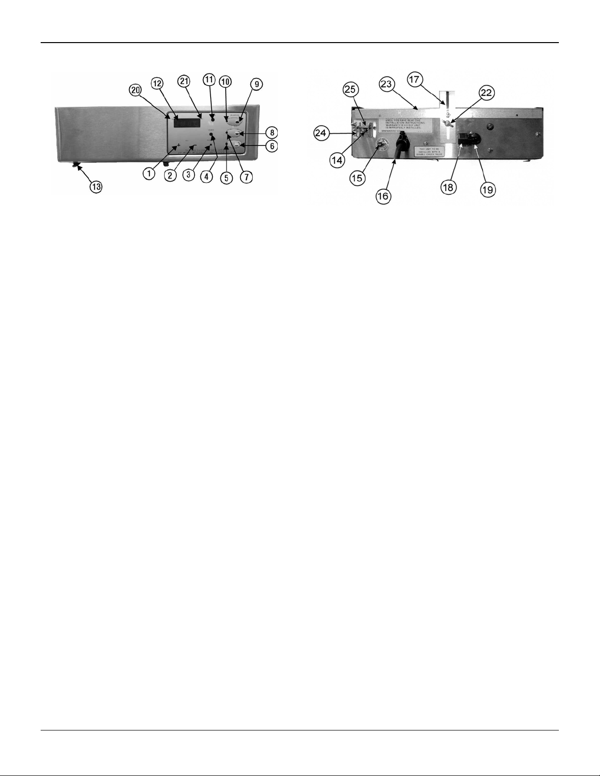
CONTROL LOCATIONS AND DESCRIPTIONS
1. “+” Button
Press to adjust the clock (hr) and or adjust the time (hr) for
“Brew Start Time”.
2. “-” Button
Press to adjust the time (min.) and or adjust the time (min.) for
“Brew Start Time”.
3. Program Button.
Press this button to change the time and selection settings.
4. Power Light.
When lit, indicates unit is in ON.
5. Quarter Brew Selection Light
Will light when Quarter Brew selection is pressed or flash
when selection is in program mode.
6. Quarter Brew Selection Button
Press this button to select Quarter Brew selection to brew
coffee.
7. Half Brew Selection Light.
Will light when Half Brew selection is pressed or flash when
Half Brew selection is in Program Mode.
8. Half Brew Selection Button
Press this button to select Half Brew selection to brew coffee.
9. Full Brew Selection Button
Press this button to brew a full carafe or decant er
10. Full Brew Selection Light
Will light when Full Brew selection is pressed or flash when
Full Brew selection is in Program Mode.
11. “Service” Light
Indicates problem with the machine and service is required.
12. Display Window
Displays the time in hours, minutes and program inform ation
13. Brew Cone Guide Rails
Slide the brew cone in here.
Fig. 1
14. Toggle Switch (On-Off-Fill)
Turns ON the power to the coffee appliance an d fills the tank
prior to use.
15. Circuit Breaker
Breaks the power to the machine.
16. Power Supply Cord
Connect this cord to appropriate wall receptacle.
17. Rear Mounting Bracket
Holds the rear of the machine
18. Plastic Nut Fitting
Insert the plastic water supply tubing here. (See item #26)
19. Plastic Water Inlet Elbow Fitting
The incoming tube polyethylene (wat er supply) connects
here.
20. LIGHT Dot Display (“PM” Indicator)
When lit, indicates time is past 12 O’clock in afternoon.
21. LIGHT Dot Display “Brew time SET” Indicator
Will light when a “Brew time” is Set.
22. Wing Nut
Secures the machine to the “L” bracket
23. Top Mounting Plate
Secure this to the underneath the cab inet.
24. Safety Bracket
Prevents the user from dry firing when the screw i s in place
during installation.
25. Safety Screw
Prevent the toggle switch from being pushed up before filling
the tank with water.
26. Plastic Tubing (Polyethylene) NOT SHOWN – 1/4” OD
Tubing supplied is 25’, cut to appropriate length before
connecting to water inlet.
Page 5

INSTALLATION INSTRUCTIONS
WARNING: Read these installation instructions completely before connecting this brewer to a power supply or water supply. The
water tank must be filled with water for this brewer to function properly.
WARNING: Incorrect installation or operating procedures will void the warranty and may damage this brewer.
Note: Any changes to the internal plumbing or wiring of the building should be performed by a licensed plumber or a licensed
electrician. Check applicable building codes and requirements for procedures and restrictions that may apply during this installation.
This appliance is designed to be mounted to the underside of a kitchen wall cabinet near a convenient source of water and
power with a minimum of 15” & a maximum of 19.5” height of space between counter and cabinet. (see optional pot sizes
under accessories on page 17.
MOUNTING: (See Mounting Diagram below for Details)
1. Check the contents of the package carefully. In addition to the brewer and these instructions, the following items should be
present. If any item is missing, contact Waterline to
arrange for a replacement.
Built-In Brewer Appliance – Part No.103 3520WL
Stainless Steel Carafe – Part No. AP-POT-MED
Mounting Brackets and Screws
Coffee Filters – Part No. 6000415WL
Plastic Polyethylene Tubing - 25 feet
Silicone Trivet – Part No. 9920564
Quick Reference Guide – ParNo.9600276WL
Instructions & Warranty Information
SET UP: (See Fig. 2)
Medium pot included requires a minimum of 18” and a maximum of 19.5”.
TO INSTALL THE APPLIANCE PROPERLY,
FOLLOW DIRECTIONS BELOW AND FIGURE 2.
NOTE: TO AVOID POSSIBLE DAMAGE TO THE
CABINET, MAKE SURE TO USE THE MOUNTING
PLATE AS A TEMPLATE TO DRILL THE TWO (2)
Fig. 2
3/32” DIA. PILOT HOLES.
MOUNTING DIAGRAM
a) Determine the desired location of the appliance.
b) Remove the brew cone from the appliance and remove the wing nut (See Fig. 2, Illus. #3 ) from the lower mounting scr ew
and slide the mounting plate out from the rear of the ap pliance.
c) Loosen, but do not remove, the nut holding the “L ” bracket to the rear of the mounting plate while hol ding the mounting
plate in place flush along the bottom edge of the cab inet facing (See Fig. 2 Illus. #1), dril l two (2) 3/32” Dia. pilot holes o n
the cabinet using the 2 holes provided on the mounting plate flange. This assures that the mounting screws will go in
easily and not damage the cabinet.
d) After drilling the two (2) pilot holes, hold the mounting plate in place (Fig. 2, Illus. #2), install two (2) screw s through the
holes provided at the front edge of the mounting plate and tighten. This will mount the front of the mounting plate.
e) While holding the mounting plate level, hold mounting “L” bracket up against the bottom of the cabinet and mark the
location of the rear mounting scre w through the sl ot in the “L” bracket. Drill a 3/3 2” pilot hol e at the marking to a ssure that
the mounting screw will go in easily and not damage the cabinet. Install the mounting screw through “L” bracket, at the
location marked.
f) Hold th e mounting plate level; tighten the nut to hold the rear of the mounting plate in pl ace.
g) Slide the appliance onto the mounting plate making sure the attac hm ent screw o n the r ear of th e ap pl ianc e fits int o th e slot
on the “L” bracket. Attach the wing nut to ho ld the appliance in place. Level the appliance and tighten the wing nut.
Note: Make sure the appliance is level. If the appliance is not level, loosen the top mounting nut and level the appliance.
Tighten nut.
Page 6
 Loading...