

WaterLine Controls WLC-9000 Installation Instructions Manual
Installation Instructions for Model WLC-9000
IMPORTANT SAFETY INSTRUCTIONS
Page 1
© SDI 2008
is the optimum choice for any situation requiring the
precise control of a water level. It is ideal for automatically maintaining the
correct level in cooling towers, storage tanks, or process water applications.
Model WLC-9000 achieves control by the use of a
corrosion resistant probes that sense the water level and then in conjunction with
electronics and a microprocessor, provides signals that can be used to open/close
valves and other control or recording devices thus maintaining correct levels.
Levolor is a registered trademark of Jandy Pool Products, Inc. and used under license only. SDI and Jandy Pool Products, Inc. are not affiliated companies.
Waterline Controls is a registered trademark of SDI.
1. Call the factory with any questions. 1-888-905-1892 or write to:
System Dynamics, P.O. BOX 12544, Scottsdale, AZ 85260
2. Read and follow all instructions.
3. Disconnect all power before opening the internal cover/s or making any connections to the unit.
4. Do not install in locations where sprinklers or other watering devices will allow water to impinge on the unit.
5. Sensor wires must be continuous and not spliced.
6. Make sure the unit is connected properly to earth ground.
7. Only qualified personnel should install this unit or replace the "replaceable" parts.
8. Only factory supplied parts should be used whenever a replaceable part is needed.
9. T
he manufacture will not be liable for any injury or damage that may arise from the misuse of this
unit or from failure to follow all of these instructions.
10. Save these instructions and provide them to the end user.
11
. This unit shall not be used in any "safety critical" application or where the failure of any function or component may cause death or personal injury
.
11. Ne pas utilisez cet élément quand les blessures oú la mort peuvent les présenter.
12. Use copper (CU) wire only for all connections.
TM
Page 2
© SDI 2008
T
he unit is powered by either 110 VAC or
220 VAC 60 HZ 0.5 Amp. The input voltage is determined by
the option selected. If the 110 VAC option is selected, then the
input power wires are: one black and one white. If the 220 VAC
option is selected, then the two input power wires are both black.
The unit is rated for indoor or outdoor installation.
These power relays may be used to control valves, or
solenoids; but not motors. There are also low power SPST
relays whose contacts are rated at 50 VAC/DC 0.25 Amp.
that can be used as an additional indicator or to provide an
indication to an event recorder, computer or automation system.
The normal indicator on the unit is a green LED that is
a "power ON" indicator and is on whenever power is applied to
the unit. There are also other LED's that turns ON whenever
the relay contacts are closed. These indicate a very high
level condition, or a DRAIN I or DRAIN II condition and will
remain ON until the level changes to some other level.
See Table 1 for the LED functions associated with the
various models. The contact with the water is sensed by
electronics and the microprocessor then provides the
necessary control for the various outputs.
The parts supplied are:
1 - The Waterline Control CONTROLLER.
1 - Stainless steel probe assembly with 50 feet of wire.
2 - U bolts with nuts.
1 - Mounting bracket.
* Power Relays (as required)
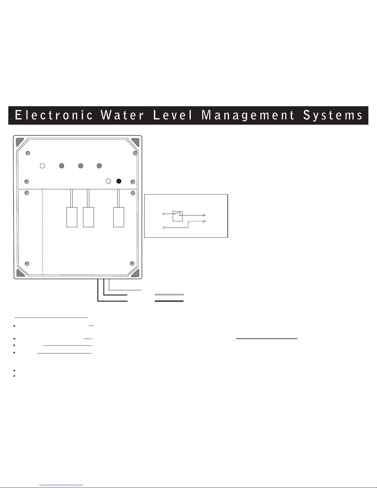
Figure 1.
WLC-8000
Sensor Low Voltage Raceway
POWER
ALARM
DRAIN I
HIGH
ALARM
TESTING
PRESS TO TEST
Green (Ground)
Black
Black
220VAC OR
110VAC
White
Black
LOW ALARM
(LA)
HIGH ALARM
(HA)
FILL
Brown
Pair
Green
Pair
Red
Pair
Quantity of relays
and lights are a
function of
the model.
"Bottom plate removed
in illustration."
DRAIN II
WLC Relay
(N.O.)
LOAD
(Solenoid, Pump,
Contactor)
* All loads combined
cannot exceed
Circuit Breaker Rating
Hot
Neutral
Single Pole Relay
LINE
(110VAC)
The "replaceable" parts are:
Waterline Control CONTROLLER part # WLC-9000 with option110 or
220 vac (specify option: 110 or 220 VAC)
Stainless steel probe assembly See Sensor assembly appendix.
Power relay part # PG8P
Solenoid part # 8221G5 (other options for voltage &
pipe size are available; Contact the factory).
This size is 110VAC 1" pipe. (optional)
U Bolts/nuts U20P5-9
Mounting bracket MB2
 Loading...