

WATERKOTTE EcoTouch DS 5027 Ai Planning And Installation Manual
WATERKOTTE GmbH, Gewerkenstraße 15, D-44628 Herne
Tel.: 0049/(0)2323/9376-0, Fax: 0049/(0)2323/9376-99, E-Mail: info@waterkotte.de
Internet: http://www.waterkotte.de
Z20555 / 2005/06/10
Planning and installation
EcoTouch DS 5027 Ai
Heating System

2005/06/10
2 / 60
Copyright 2013 by: WATERKOTTE GmbH. Subject to changes.
Copyright 2013 by:
WATERKOTTE GmbH,
Gewerkenstraße 15, 44628 Herne, Germany
All rights reserved. Reproduction, duplication as well as translation of this
publication, or excerpts therefrom, require prior written approval by
WATERKOTTE GmbH.
Illustrations and diagrams serve as explanatory description and shall not be
used as drawings for construction, offers or installation.
All specifications comply with the state of technology at time of
printing; we reserve the right to make changes
that serve technical progress.
This publication has been prepared with all reasonable care.
WATERKOTTE GmbH does not assume any liability for remaining
errors or omissions, or for possible damages.

2005/06/10
3 / 60
Copyright 2013 by: WATERKOTTE GmbH. Subject to changes.
Content
1 Safety ..................................................................................................................................... 6
1.1 Intended use ...................................................................................................................... 6
1.2 Basic safety precautions .................................................................................................... 6
1.2.1 Keep information available .................................................................................... 6
1.2.2 Before initial use .................................................................................................... 6
1.2.3 Enviroment protection ........................................................................................... 6
1.2.4 Modifications and repairs on the heat pump ......................................................... 7
1.3 Hazards ............................................................................................................................. 7
1.4 Specific types of hazards ................................................................................................... 8
1.5 Operator's duty of care ...................................................................................................... 9
1.6 Other applicable documents .............................................................................................. 9
2 Functional principle of heat pump .......................................................................................... 10
3 Product description ............................................................................................................... 11
3.1 Overview (connected device) ........................................................................................... 11
3.2 Overview (unit opened) .................................................................................................... 12
4 Components and installation .................................................................................................. 13
4.1 Heating system EcoTouch DS 5027 Ai ............................................................................ 13
4.2 Installation ....................................................................................................................... 13
4.2.1 Heat pump system series EcoTouch DS 5027 Ai ................................................ 13
4.2.2 Heat pump module ............................................................................................. 13
4.3 Electrical equipment ........................................................................................................ 14
4.3.1 Electrical resistance heating ................................................................................ 14
4.4 Domestic hot water heating system ................................................................................. 14
4.4.1 Heatsource ......................................................................................................... 14
4.4.2 Electronic heat pump control .............................................................................. 14
4.4.3 Sensors .............................................................................................................. 15
4.4.4 COP-Counter ...................................................................................................... 15
4.5 Options ............................................................................................................................ 15
4.6 Model EcoTouch DS 5027Ai NC ..................................................................................... 16
4.7 Model EcoTouch DS 5027Ai RC ...................................................................................... 17
5 Transport .............................................................................................................................. 18
5.1 Transport to installation site ............................................................................................. 19
6 Installation............................................................................................................................. 20
6.1 Environmental conditions for installation .......................................................................... 20
6.2 Creating the foundation and installing heat pump ............................................................ 21
6.2.1 Laying a foundation for acoustic heat pump ....................................................... 21
6.2.2 Dimensions concrete plinth (mm): ....................................................................... 21
6.3 Installation of the housing ................................................................................................ 22

2005/06/10
4 / 60
Copyright 2013 by: WATERKOTTE GmbH. Subject to changes.
6.3.1 Removing the housing ........................................................................................ 22
7 Installation and connection .................................................................................................... 23
7.1 Connections EcoTouch DS 5027 Ai (rear) ........................................................................ 23
7.2 Connection to heating system ......................................................................................... 23
7.2.1 Heat pump with underfloor heating ..................................................................... 25
7.2.2 Heat pump with radiators ................................................................................... 25
7.2.3 Heat pump with swimming pool.......................................................................... 25
7.3 Connection to heat source .............................................................................................. 26
7.3.1 Water glycol systems .......................................................................................... 28
7.3.2 Groundwater heat source ................................................................................... 28
7.3.3 Groundwater quality............................................................................................ 28
7.3.4 Flow monitoring .................................................................................................. 30
8 Electrical work ....................................................................................................................... 31
8.1 8.1 Electrical installation ................................................................................................... 31
8.2 Electrical heat generator for startup and standby ............................................................. 32
8.2.1 Startup of electrical heat generator (EWE) ........................................................... 32
8.2.2 Parallel operation: Heat pump and electrical heat generator ............................... 33
8.2.3 Heat generator, thermostat settings .................................................................... 33
8.3 Installation instructions for external sensor ....................................................................... 33
8.3.1 Cabeling ............................................................................................................. 33
8.4 Electrical connections ...................................................................................................... 34
8.4.1 EcoTouch DS 5027 Ai (3x 400 V) ....................................................................... 34
8.4.2 EcoTouch DS 5027 Ai (1x 230 V) ....................................................................... 35
8.4.3 Connectors ......................................................................................................... 36
8.4.4 Controller WWPR 2 ............................................................................................. 37
9 Pipe & instrumentation flow chart/measurement & control technology ..................................... 38
10 Hydraulic diagramms DS 5027Ai & DS 5027Ai NC / RC .......................................................... 40
11 Commissioning ..................................................................................................................... 42
11.1 Pre-startup checks .......................................................................................................... 42
11.2 Initial start-up of machine ................................................................................................. 43
11.3 Control of entire operation ............................................................................................... 44
11.4 Turning heat pump off ..................................................................................................... 45
11.5 Taking heat pump out of operation for extended period .................................................. 45
12 Troubleshooting .................................................................................................................... 46
12.1 Possible faults and solutions ............................................................................................ 46
12.1.1 Fault at input side (LP fault) ................................................................................. 46
12.1.2 Fault at output side (HP fault) .............................................................................. 46
12.1.3 Fault in circulation pumps ................................................................................... 46
12.1.4 Fault in compressor motor .................................................................................. 46
13 Safety measures ................................................................................................................... 47
13.1 Pressure limits of compressor .......................................................................................... 47
13.2 Motor protection against excessive temperature ............................................................. 47
13.3 Refrigerator oil ................................................................................................................. 47

2005/06/10
5 / 60
Copyright 2013 by: WATERKOTTE GmbH. Subject to changes.
14 Maintenance and care ........................................................................................................... 48
15 Connection diagrams ............................................................................................................ 49
15.1 Description of the parts in the connection diagram .......................................................... 56
16 Technical Data ...................................................................................................................... 58
Note: This symbol mark applies only to countries within the European Union
(EU). This symbol mark is in compliance with Directive 2002/96/EC, Article
10. The product has been designed and manufactured with high-quality
materials and components which are suitable for recycling.
This symbol means that electrical and electronic equipment, at the end of
its useful life, shall be disposed of separately from household waste. Please
dispose of this equipment at your designated collection point or local recycling.
In the European Union, different collection systems are available for used
electrical and electronic equipment. Please help us conserve the environment we live in!
Do not release refrigerant R410A into the atmosphere:
R410A is a greenhouse gas according to Kyoto Protocol and has a global
warming potential (GWP) of 1975.
Do not release refrigerant R134a into the atmosphere:
R134a is a greenhouse gas according to Kyoto Protocol and has a global
warming potential (GWP) of 1300.

Safety
2005/06/10
6 / 60
Copyright 2013 by: WATERKOTTE GmbH. Subject to changes.
1 Safety
1.1 Intended use
Your WATERKOTTE heat pump is used for space heating and cooling, and
domestic water heating.
Project planning of the heat source system must be performed in compliance with the technical information provided by WATERKOTTE for layout of
heat source systems.
Heat pump shall only be turned on after the refrigerant connections are
completely filled, and the other hydraulic circuits are completely filled and
vented, and all electrical connections are properly completed.
Commissioning may only be carried out by trained professionals. Damages
caused by non-compliance with above mentioned items are not covered by
the warranty (see enclosed Exclusion of Warranty).
1.2 Basic safety precautions
1.2.1 Keep information available
1.2.2 Before initial use
In addition to the operating manual, also furnish operating instructions in
terms of Labour Protection Law and Work Equipment ordinance.
Keep all safety and operating signs on the heat pump in fully legible condition at all times. Replace damaged or illegible signs immediately.
Before initial use of your WATERKOTTE heat pump, familiarise yourself with:
Operating and control elements of your WATERKOTTE heat pump
Equipment of heat pump
Operation of heat pump
Immediate surroundings of heat pump
Safety devices of heat pump
Before initial start, perform the following steps:
Ensure that all safety devices are installed and function as intended.
Check heat pump for visible damage. Remedy any detected defects
immediately. Heat pump must be in perfect condition during operation!
Ensure that only authorised personnel is in the work area of the heat
pump and that no other persons are endangered when heat pump is
started.
1.2.3 Enviroment protection
Remove all objects and other materials that are not required for opera-
tion of the heat pump from the work area of the heat pump.
Observe the regulations regarding waste avoidance and proper waste
recycling or disposal when performing any kind of work on and with the
heat pump.

Safety
2005/06/10
7 / 60
Copyright 2013 by: WATERKOTTE GmbH. Subject to changes.
Ensure that particularly during installation and maintenance work, as well
as when placing out of operation, pollutants such as grease, oil, refrigerant, solvent- containing cleaning fluids, etc. do not contaminate the
ground or enter the sewer system!!
These materials must be collected, stored, transported and disposed of
in appropriate containers
1.2.4 Modifications and repairs on the heat pump
For safety reasons, no unauthorised modifications shall be performed on
the heat pump.
Thus, all intended modifications are subject to written approval by
WATERKOTTE.
Use only original spare parts from WATERKOTTE. Original spare parts are
specially designed for your heat pump. Externally procured parts provide no
guarantee that they are designed and manufactured in compliance with relevant usage and safety requirements.
Parts and special equipment not delivered by WATERKOTTE are not approved for use on the heat pump.
1.3 Hazards
Observe the following points to avoid life-threatening injuries and damages
to the heat pump during operation:
Warning! Risk of electric shock!
Do not use water or other liquids to clean the unit!
Keep all electrical supply units locked at all times!
Any work on the electrical equipment of the heat pump shall only be performed by professional electricians!
Discharging refrigerant can cause severe personal injury (suffocation or hypothermia)!
Avoid contact with refrigerant!
Note the minimum volume of the installation room and consider the type of
the refrigerant (EN 378-1).
Warning! Risk of suffocation!
The packaging is not a toy! The packaging must be disposed of environmentally acceptable.
Risk of burns!
During operation, surface temperatures (compressor and pressure line) can
climb above 100 °C or drop below 0 °C.
Do not remove housing cover during operation!
Allow heat pump to cool down before removing cover.

Safety
2005/06/10
8 / 60
Copyright 2013 by: WATERKOTTE GmbH. Subject to changes.
Risk of injury!
Risk of chemical burns when skin comes in direct contact with lubricant
leak.
Wear suitable clothing when performing maintenance work on the heat
pump!
Risk of injury in case of leakage in cooling circuit!
Skin contact with refrigerant may cause freezing of tissue and frostbites.
High vapour concentrations can cause headaches, dizziness, fatigue, nausea and even unconsciousness. Irregular heartbeat (arrhythmia).
Avoid contact with refrigerant! Do not expose to heat, sparks, naked light or
other ignition sources
Electrostatic charge!
Electronic components can be damaged by electrostatic processes.
Ground yourself before touching electronic Ground yourself before touching
electronic components.
Risk of total loss!
Repeated restart of heat pump can result in total loss!
In case of heat pump failure, before restart an inspection by qualified and
authorised personnel must be performed.
Due to test bench operation, the heat pump can have ethylene glycol residues.
1.4 Specific types of hazards
To avoid damage to machine or life-threatening injuries during installation of
machine, the following points must be observed:
Machine parts that are improperly placed or incorrectly attached can fall
down or overturn.
Sharp-edged machine parts that are still exposed and accessible can
result in injury.
Incorrectly installed lines (e.g. insufficient bending radius) can cause
smouldering and cable fires.
Risk of chemical burns when skin comes in direct contact with lubricant
leak.
Electronic components can be damaged by electrostatic processes.

Safety
2005/06/10
9 / 60
Copyright 2013 by: WATERKOTTE GmbH. Subject to changes.
During operation, surface temperatures (compressor and pressure line)
1.5 Operator's duty of care
Your WATERKOTTE heat pump has been designed and built on the basis
of a risk analysis and after careful selection of standards to be observed.
Thus, your heat pump is state-of-the-art and provides for maximum safety.
In practice, however, this safety can only be ensured by taking all necessary
measures. As operator of the heat pump it is your responsibility to plan
these measures and oversee their implementation.
You must ensure that:
The heat pump is only used as intended (see also chapter 1.1, „Intend-
The heat pump is only operated in perfect, fully functional condition and
can climb above 100 °C or drop below 0 °C. Serious burns/frostbites
can occur. Before working on the compressor: Switch off unit and allow
to cool down.
ed use“).
safety devices are checked regularly to ensure that they are work-ing
properly.
The operating manual is available in perfect condition at the heat pump
at all times.
The heat pump is operated, maintained and repaired only by ade-
quately qualified and authorised personnel.
None of the safety and warning notices on the heat pump are removed
or damaged.
1.6 Other applicable documents
Operating manual: WWPR WATERKOTTE Heat pump controller.

Functional principle of heat pump
2005/06/10
10 / 60
Copyright 2013 by: WATERKOTTE GmbH. Subject to changes.
Heat source
Low temperature
Driving energy
Energy output
Heat pump
2 Functional principle of heat pump
The heat pump is used to produce thermal energy for space heating and, if
required, domestic water heating. The medium used as heat source (WQ) is
the ground.
It is also possible to cool a building.
To utilise ground as thermal energy, for domestic water heating and cooling in your home, you need the following:
a heat source (borehole with geothermal energy probes or groundwater
extraction / discharge)
heating system EcoTouch DS 5027 Ai
domestic hot water tank
Figure 1: Energy share when using a geothermal energy pump
Product description
2005/06/10
11 / 60
Copyright 2013 by: WATERKOTTE GmbH. Subject to changes.
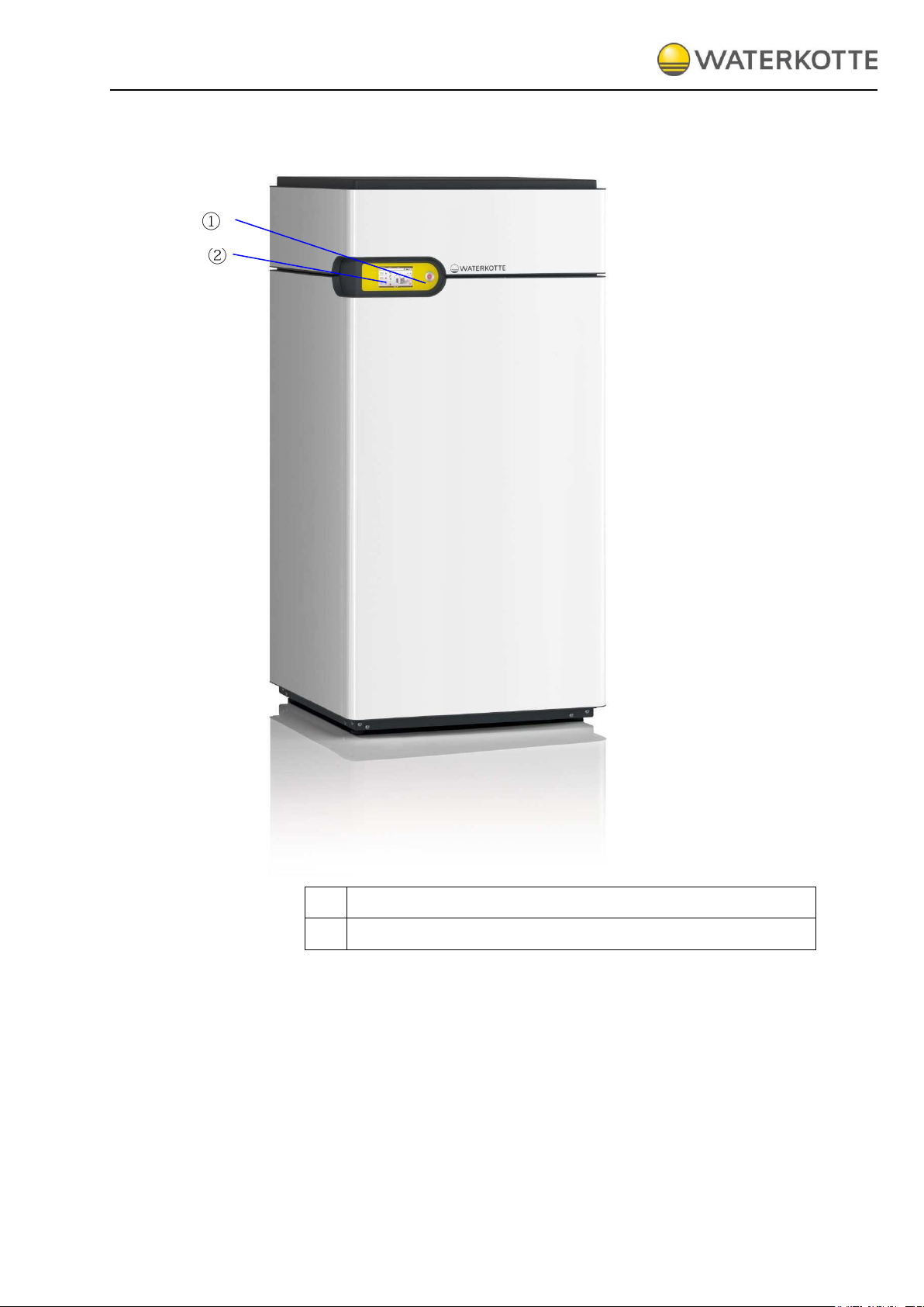
1
ON / OFF switch
2
Control panel (electronic heat pump controller)
3 Product description
3.1 Overview (connected device)
Figure 2
: Heating system EcoTouch DS 5027 Ai
Product description
2005/06/10
12 / 60
Copyright 2013 by: WATERKOTTE GmbH. Subject to changes.
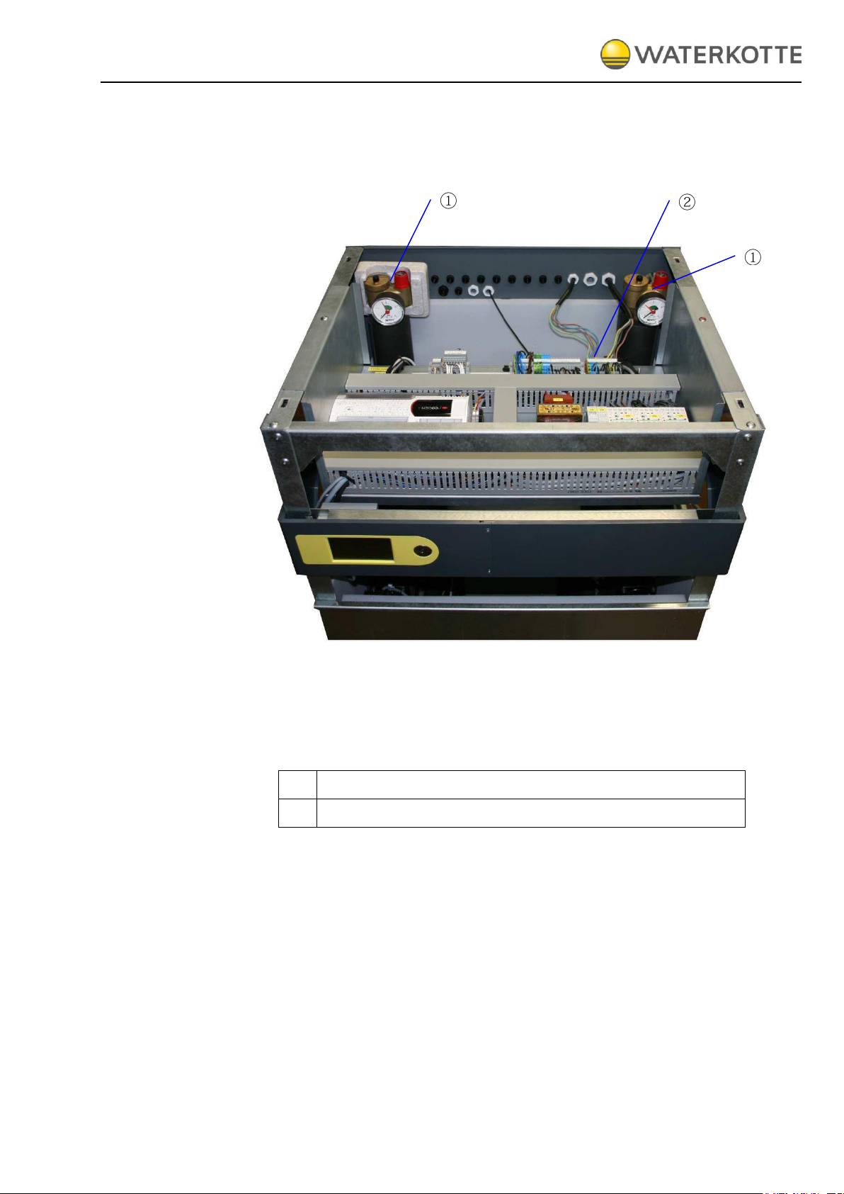
1
Safety group with manometer: relief valve, bleeder
2
Connecting terminal
3.2 Overview (unit opened)
Figure 3: EcoTouch DS 5027 Ai (Top view, opened)
Components and installation
2005/06/10
13 / 60
Copyright 2013 by: WATERKOTTE GmbH. Subject to changes.
4 Components and installation
4.1 Heating system EcoTouch DS 5027 Ai
All components of the heating system are mounted in a protective steel
plate housing which is intended for installation inside. The base frame consists of a bent, thick-walled sheet steel. Together with the rear panel frame,
which also consists of a thick-walled sheet steel, it forms a unit. Side panels, cover, front and the tilt-mounted, ergonomic control panel can be removed.
All housing parts are optionally available in high-gloss white or stainless
steel finish. Sound insulation ensures low noise emissions.
4.2 Installation
4.2.1 Heat pump system series EcoTouch DS 5027 Ai
Funtions: Heat pump, domestic hot water heating system, electrical resistance heating for startup and standby, regulation and electrical control,
touch display with Easy-Con Software, smartphone control via Easy-Con
Mobile software, diagnosis system.
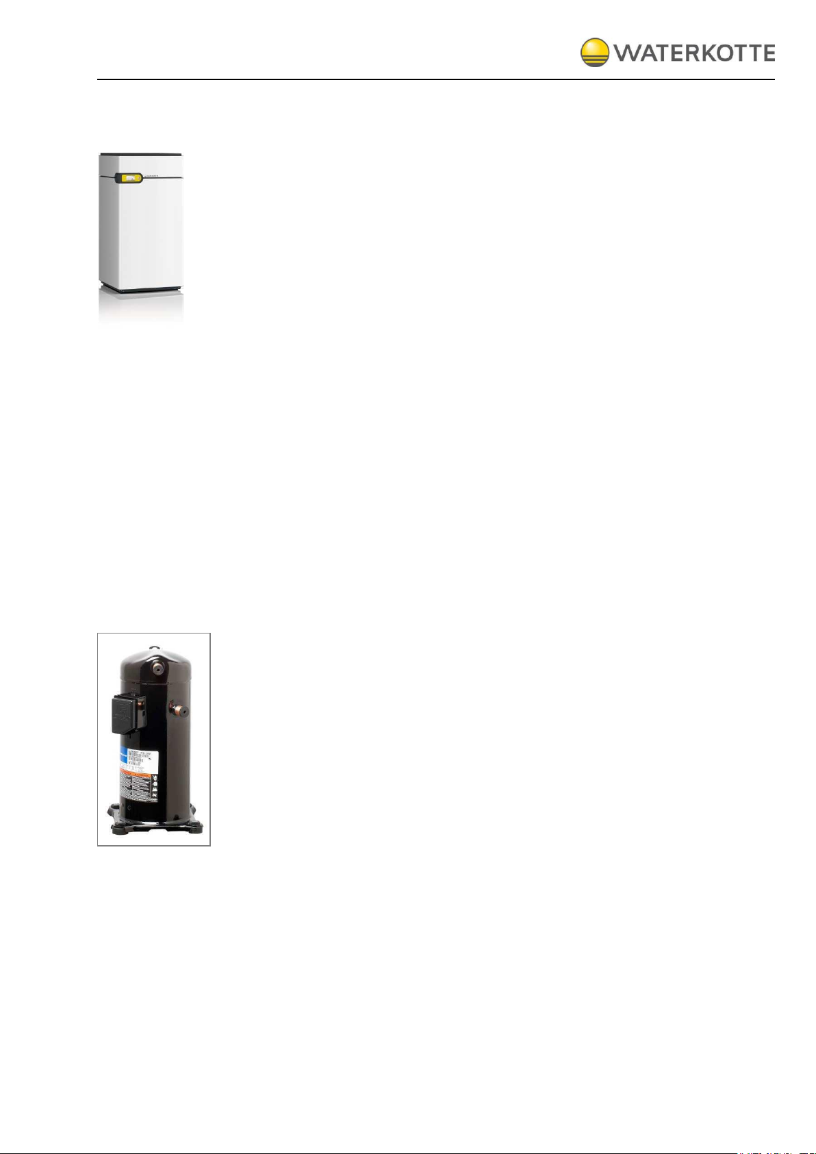
4.2.2 Heat pump module
All hydraulic connections are placed on the back side. All modules in the
frame-work are law vice fitted with removable, heat and sound insulated
housing, color signal white (RAL 9003) or stainless steel.
The compressor features a fully hermetic design in approved leading scroll
technology (fig. left). Evaporator and condenser are designed as soldered
stainless steel plate packs with reverse flow circuits, according to state-ofthe-art development, tailored to the new non-flammable safety refrigerants
that will be required by law in the future. In combination with ester oil
(biodegradable), this guarantees optimum lubrication conditions, low friction
losses and therefore the highest possible life expectancy for the
compressor according to the latest industrial research findings.
The cooling circuit is designed in accordance with the relevant safety regulations. Manufacturing quality is carried out based on ISO 9000ff, supplemented by an automated computer-monitored quality test (pressure stress
and helium leak test) in addition to inspection of all parameters in a subsequent trial run.

Components and installation
2005/06/10
14 / 60
Copyright 2013 by: WATERKOTTE GmbH. Subject to changes.
4.3 Electrical equipment
The electrical connections are made via the internal terminal (on the construction profile). The implementation of the electrical cable is carried by the
rear wall (with the strain relief).
The internal terminal connects the entire sensor, all queries, all relay outputs, digital circuit, the compressor and the electrical heating element. The
WATERKOTTE WWPR-controller is supplied with a control panel mounted
on the 24 V AC transformer.
4.3.1 Electrical resistance heating
Located in the heating flow, power 6 kW. Used to support initial heating in
the winter and during the standby function.
4.4 Domestic hot water heating system
Consisting of: heating circulation pump (speed-controlled / energy class A),
air separator with automat. air diverter, filling pressure gauge, overpressure
safety valve, filling valve, large expansion tank, 12 or 18 liters; connections
for heating flow and return are fitted externally to facilitate installation in the
rear panel frame.
4.4.1 Heatsource
Consisting of: heating circulation pump (speed-controlled / energy class A),
air separator with automat. air diverter, filling pressure gauge, overpressure
safety valve, large expansion tank 12 liters, connections for heating flow
and return are fitted externally to facilitate installation in the rear panel
frame.
4.4.2 Electronic heat pump control
The heat pump control (control panel is pictured) is included in the delivery
scope of the WATERKOTTE heat pump.
Use in other than WATERKOTTE heat pumps will void any warranty claim.
The control is used to control and monitor heating systems that are operated with WATERKOTTE compact heat pumps according to technical guidelines of WATERKOTTE Wärmepumpen GmbH.
The following tasks are performed: everything to do with regulation (depending on the external temperature with pilot room guidance), control,
monitoring, self-diagnosis, saving of data in cases of breakdown.
WATERKOTTE explicitly states that function warranty will become void if
used on systems not approved by WATERKOTTE. Any liability for consequential damages due to incorrect function within these systems shall be
explicitly excluded.

Components and installation
2005/06/10
15 / 60
Copyright 2013 by: WATERKOTTE GmbH. Subject to changes.
4.4.3 Sensors
4.4.4 COP-Counter
4.5 Options
Info: Technical details, operation and warning messages (see
manual for Heat pump control)
.
Operating
The control's sensor system consists of:
Pressure transmitter for evaporation and condensation pressure, sensors
for temperature detection in all circuits. External wall sensor in accessories
kit, reference room sensor and hot water sensor (optional).
A WATERKOTTE COP counter is already integrated in the heat pump control. For additional information, please refer to operating manual for heat
pump control.
Domestic hot water: thermo storage/charging storage (heating side), potable water heater, temperature sensor, three way valve.
Expansion kit: For pool heating, thermal use of solar energy, mixer circuits.
Buffer tank: Standard tank, supply loading tank with additional control.
Heat source accessories: Heat exchanger for ground water, flow rate monitoring, antifreeze concentrate, heat source distributor.
Solar accessories: Sensor, additional control module, heat exchanger, solar
collectors
Heating: Underfloor heating system, underfloor heating head station, distribution cabinet, convectors
Heat pump accessories: Digital soft starter (for retrofitting at 3 x 400V compressor design), basement pad.
More accessories: Reference room sensor.
Special models: Natural cooling, active cooling.

Components and installation
2005/06/10
16 / 60
Copyright 2013 by: WATERKOTTE GmbH. Subject to changes.
4.6 Model EcoTouch DS 5027Ai NC
The model EcoTouch DS 5027 Ai NC is a variant of series EcoTouch DS
5027 Ai with the option of natural cooling, while maintaining all basic features. Natural cooling means an expansion of thermal comfort to the summer months.
Prerequisites for natural cooling: Natural cooling is only possible in connection with a low temperature floor surface exchange system or fan coils.
Same as with any other type of cooling, the rooms must be protected
against sunlight. Cooling does not help during direct sun exposure.
The heat source must be suitable for cooling operation. Particularly suitable are:
Geothermal energy probes: heat source is regenerated with renewable
energy from your building (thermal planning is essential).
Groundwater, with groundwater, cooling operation is practically unlim-
ited in terms of power.
To realize the natural cooling system (separation mode) the execution the
EcoTouch DS 5027 Ai NC is equipped with an separation heat exchanger.
During cooling operation, the heat source circuit is applied to the separation heat exchanger on one side, and the heating circuit on the other side.
The control of the flow temperature is subject to the "source" pump twostep-control which ensures that the inlet temperature into the floor heat
transfer system does not exceed the dew point of the air.

Components and installation
2005/06/10
17 / 60
Copyright 2013 by: WATERKOTTE GmbH. Subject to changes.
4.7 Model EcoTouch DS 5027Ai RC
The model EcoTouch DS 5027 Ai RC is a variant of series EcoTouch DS
5027 Ai with the option of active cooling, while maintaining all basic features. Active cooling means an expansion of thermal comfort to the summer months
Prerequisites for natural cooling: Active cooling is only possible in connection with a low temperature floor surface exchange system or fan coils.
Same as with any other type of cooling, the rooms must be protected
against sunlight. Cooling does not help during direct sun exposure.
The heat source must be suitable for cooling operation. Particularly suitable
are:
Geothermal energy probes: heat source is regenerated with renewable
energy from your building (thermal planning is essential).
Groundwater, with groundwater, cooling operation is practically unlim-
ited in terms of power.
In cooling mode, the internal cooling circuit is reversed while a 4-way solenoid valve is switched
The system is controlled by the heating return temperature. The required
temperature in the cooling circuit is derived from the desired cooling temperature and the settings in the time program.
In floor heating systems, this value should be only slightly below the desired room temperature (21 ... 23 °C). The nominal value including hysteresis is limited downwards to 15 ° C. This avoids an underflow below the dew
point in cold areas, pipelines, and plant parts.
When mounting in a maritime climate (high humidity) you have also to consider the demand "dehumidify" in the design of heat or cold transmission.
Transport
2005/06/10
18 / 60
Copyright 2013 by: WATERKOTTE GmbH. Subject to changes.
5 Transport
Exercise particular caution when transporting the units. Since the unit
weighs 150 kg or more, at least two people are required for transport.
Do not use the packaging straps to carry the unit. Wear protective
gloves for unpacking and transporting the unit to prevent hand injuries
from cooling fins or other parts.
Observe the transport instructions on the package.
Observe the specified storage requirements.
The units may not be stacked
Machine may only be lifted at the provided attachment points.
Machine may only be transported in upright position.
Ensure proper disposal of packaging materials. Packaging materials,
such as nails or other metal or wooden parts, may cause injuries.
Please also read chapter "General safety information”
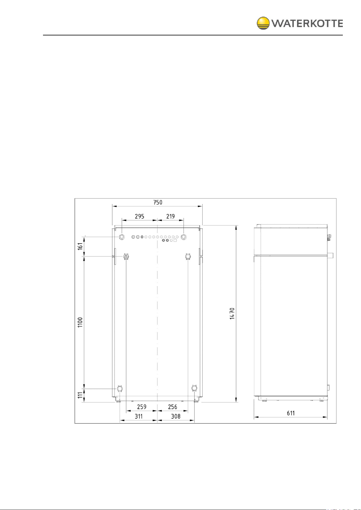
Figure 4: Dimensions DS 5027 Ai (without packaging)
 Loading...