

WATERKOTTE EcoTouch Ai1 Geo, EcoTouch DS 5018 Ai Planning And Installation Manual
21.11.2015
1 / 76
Z20469
Copyright 2013 by: WATERKOTTE GmbH. Subject to changes.
Planning and installation
EcoTouch Ai1 Geo /
EcoTouch DS 5018 Ai
Heating station
WATERKOTTE GmbH, Gewerkenstraße 15, D-44628 Herne
Tel.: +49 2323 9376 0, Fax: +49 2323 9376 99
Service: +49 2323 9376 350
E-Mail: info@waterkotte.de Internet: http://www.waterkotte.de

21.11.2015
2 / 76
Z20469
Copyright 2013 by: WATERKOTTE GmbH. Subject to changes.
Copyright 2013 by:
WATERKOTTE GmbH
Gewerkenstraße 15, 44628 Herne, Germany
All rights reserved. Reproduction, duplication as well as translation of this pub-
lication, or excerpts therefrom, require prior written approval by WATERKOTTE
GmbH.
Illustrations and diagrams serve as explanatory description and shall not be
used as drawings for construction, offers or installation.
All specifications comply with the state of technology at time of
printing; we reserve the right to make changes that serve technical progress.
This publication has been prepared with all reasonable care.
WATERKOTTE GmbH does not assume any liability for remaining errors or
omissions, or for possible damages.

21.11.2015
3 / 76
Z20469
Copyright 2013 by: WATERKOTTE GmbH. Subject to changes.
Content
1 Safety ..................................................................................................................................... 6
1.1 Intended use ...................................................................................................................... 6
1.2 Basic safety precautions .................................................................................................... 6
1.2.1 Keep information available .................................................................................... 6
1.2.2 Before initial use .................................................................................................... 6
1.2.3 Environmental protection ...................................................................................... 7
1.2.4 Modifications and repairs on the heat pump ......................................................... 7
1.3 Hazards ............................................................................................................................. 7
1.4 Specific types of hazards ................................................................................................... 9
1.5 Operator's duty of care ...................................................................................................... 9
1.6 Other applicable documents .............................................................................................. 9
2 Functional principle of heat pump .......................................................................................... 10
2.1 Description ...................................................................................................................... 10
3 Product describtion ............................................................................................................... 11
3.1 Overview .......................................................................................................................... 11
4 Components and installation .................................................................................................. 14
4.1 Heating system EcoTouch Ai1 Geo ................................................................................. 14
4.2 Structure .......................................................................................................................... 14
4.2.1 Heat pump module ............................................................................................. 14
4.2.2 Compressor ........................................................................................................ 15
4.3 Electrical equipment......................................................................................................... 15
4.3.1 Electrical resistance heating ................................................................................ 15
4.3.2 Domestic hot water heating system .................................................................... 15
4.3.3 Natural cooling .................................................................................................... 15
4.3.4 Heat source ........................................................................................................ 15
4.3.5 Electronic heat pump control .............................................................................. 16
4.3.6 Sensors .............................................................................................................. 16
4.3.7 COP counter ....................................................................................................... 16
4.3.8 Options ............................................................................................................... 16
4.4 Hydraulical equipment ..................................................................................................... 17
4.4.1 Domestic water heating technology .................................................................... 17
4.4.2 Domestic hot water tank (not DS 5018) .............................................................. 17
4.4.3 Heat transfer medium ......................................................................................... 17
4.4.4 Use of passive Cooling........................................................................................ 17
5 Transport .............................................................................................................................. 18
5.1 Transport to installation site ............................................................................................. 19
6 Installation ............................................................................................................................ 20
6.1 Environmental conditions for installation ........................................................................... 20
6.2 Creating the foundation and installing heat pump ............................................................ 21
6.2.1 Installation of heat pumps ................................................................................... 21
7 Installation of heat pump and domestic hot water tank ............................................................ 22
7.1 Connection accessories ................................................................................................... 22
7.2 Installation ........................................................................................................................ 23
7.2.1 Installation of the heat pump module .................................................................. 23

21.11.2015
4 / 76
Z20469
Copyright 2013 by: WATERKOTTE GmbH. Subject to changes.
7.2.2 Preparation of the assembly (EcoTouch Ai1 Geo) ............................................... 23
7.2.3 Assembly of the heat pump (EcoTouch Ai1 Geo) ................................................ 24
7.2.4 Connection tube of the tank (at the top) (EcoTouch Ai1 Geo) .............................. 25
7.2.5 Connection tube of the tank (bottom) (EcoTouch Ai1 Geo).................................. 25
7.2.6 Installation of the connection terminal(EcoTouch Ai1 Geo) .................................. 26
7.2.7 Connection terminal (compressor and e-heater (230 V) (EcoTouch Ai1 Geo) ...... 27
7.2.8 Installation of the temperature sensor (EcoTouch Ai1 Geo) ................................. 29
7.2.9 Installation of the Touch Display .......................................................................... 31
7.2.10 Installation of the housing .................................................................................... 32
7.2.11 Removing the housing ........................................................................................ 33
8 Installation and connection .................................................................................................... 34
8.1 Overview (rear side) (EcoTouch Ai1 Geo) ......................................................................... 34
8.2 Dimensions (EcoTouch Ai1 Geo) ...................................................................................... 35
8.3 Connections (rear side) DS 5018 Ai ................................................................................. 36
8.4 Connections and dimensions DS 5018 Ai ........................................................................ 37
8.5 Connection to heating system ......................................................................................... 38
8.5.1 Installations provided by customer ...................................................................... 38
8.5.2 Heat pump with underfloor heating ..................................................................... 39
8.5.3 Heat pump with radiators (natural cooling not possible) ...................................... 39
8.5.4 Heat pump with swimming pool .......................................................................... 39
8.6 Connection to heat source ............................................................................................... 40
8.6.1 Residual head ..................................................................................................... 41
8.6.2 Water glycol systems .......................................................................................... 42
8.6.3 Groundwater heat source ................................................................................... 42
8.6.4 Groundwater quality ............................................................................................ 42
8.6.5 Natural cooling .................................................................................................... 44
8.6.6 Water-Glycol mixture in the installation ................................................................ 44
8.6.7 Flow monitoring .................................................................................................. 45
9 Electrical work ....................................................................................................................... 46
9.1 Electrical installation ......................................................................................................... 46
9.2 Electrical heat generator for startup and standby ............................................................. 47
9.2.1 Initial heating of buildings during winter months .................................................. 47
9.2.2 Startup of electrical heat generator (EWE) ........................................................... 48
9.2.3 Parallel operation: Heat pump and electrical heat generator ................................ 48
9.2.4 Heat generator, thermostat settings .................................................................... 48
9.3 Installation instructions for external sensor ....................................................................... 49
9.3.1 Cabling ............................................................................................................... 49
9.3.2 Connecting terminal ............................................................................................ 50
9.4 Electrical connections ...................................................................................................... 51
9.4.1 Electrical switchboard EcoTouch Ai1 Geo (3x 400 V) .......................................... 51
9.4.2 Electrical switchboard EcoTouch Ai1 Geo (1x 230 V) ......................................... 52
9.4.3 Electrical switchboard EcoTouch DS 5018 Ai (3x 400 V) ..................................... 53
9.4.4 Electrical switchboard EcoTouch DS 5018 Ai (1x 230 V) ..................................... 54
9.4.5 Connections........................................................................................................ 55
10 WWPR controler ................................................................................................................... 56
11 Pipe & instrumentation / measurement & control technology ................................................... 57
12 Hydraulic diagramm EcoTouch Ai1 Geo ................................................................................. 58
13 Commissioning ..................................................................................................................... 59
13.1 Pre-startup checks .......................................................................................................... 60

21.11.2015
5 / 76
Z20469
Copyright 2013 by: WATERKOTTE GmbH. Subject to changes.
13.2 Initial start-up of the machine ........................................................................................... 61
13.3 Control of entire operation ............................................................................................... 62
13.4 Turning heat pump off...................................................................................................... 62
13.5 Taking heat pump out of operation for extended period................................................... 62
14 Troubleshooting .................................................................................................................... 63
14.1 Possible faults and solutions ............................................................................................ 63
14.1.1 Fault at input side (LP fault) ................................................................................. 63
14.1.2 Fault at output side (HP fault) .............................................................................. 63
14.1.3 Fault in compressor motor .................................................................................. 63
15 Safety measures ................................................................................................................... 64
15.1 Pressure limits of compressor .......................................................................................... 64
15.2 Motor protection against excessive temperature .............................................................. 64
15.3 Refrigerator oil ................................................................................................................. 64
16 Maintenance and care ........................................................................................................... 65
17 Connection diagrams ........................................................................................................... 66
17.1 Eco Touch Ai1 Geo with underfloor heating system (integrated system) .......................... 66
17.2 Eco Touch Ai1 Geo with underfloor heating system and single room control
(integrated system) .......................................................................................................... 67
17.3 Eco Touch Ai1 Geo with underfloor heating system and single room control
(system separation) .......................................................................................................... 68
17.4 Eco Touch DS 5018 Ai with underfloor heating system, single room control and
decentral hot water production ........................................................................................ 69
17.5 Eco Touch DS 5018 Ai with underfloor heating system, single room control and central
hot water production ....................................................................................................... 70
17.6 Eco Touch DS 5018 Ai with underfloor heating system, single room control, hot
water production and thermo storage .............................................................................. 71
17.7 Description of the parts in the connection diagram .......................................................... 72
18 Technical data ...................................................................................................................... 74
Note: This symbol mark applies only to countries within the European Union (EU).
This symbol mark is in compliance with Directive 2002/96/EG, Article 10. The
product has been designed and manufactured with high-quality materials and
components which are suitable for recycling.
This symbol means that electrical and electronic equipment, at the end of its useful life, shall be disposed of separately from household waste. Please dispose of
this equipment at your designated collection point or local recycling centre.
In the European Union, different collection systems are available for used electrical
and electronic equipment. Please help us to conserve the environment we live in!
Do not release R410A into the atmosphere:
R410A is a fluorinated greenhouse gas according to Kyoto Protocol and has a
global warming potential (GWP) of 1980.

Safety
21.11.2015
6 / 76
Z20469
Copyright 2013 by: WATERKOTTE GmbH. Subject to changes.
1 Safety
1.1 Intended use
Your WATERKOTTE heat pump is used for space heating and cooling, and heating of domestic water.
Project planning of the heat source system must be performed in compliance with
the technical information provided by WATERKOTTE for layout of heat source systems.
Heat pump shall only be turned on after the refrigerant connections are completely
filled, and the other hydraulic circuits are completely filled and vented, and all electrical connections are properly completed.
Commissioning may only be carried out by trained professionals. Damages
caused by non-compliance with above mentioned items are not covered by the
warranty (see enclosed Exclusion of Warranty).
Risk of total loss!
The device may only be switched on when the hydraulic circuits are completely
filled and vented, and all electrical connections are properly.
1.2 Basic safety precautions
1.2.1 Keep information available
In addition to the operating manual, also furnish operating instructions in terms of
Labour Protection Law and Work Equipment ordinance.
Keep all safety and operating signs on the heat pump in fully legible condition at all
times. Replace damaged or illegible signs immediately.
1.2.2 Before initial use
Before initial use of your WATERKOTTE heat pump, familiarise yourself with:
Operating and control elements of your WATERKOTTE heat pump
Equipment of heat pump
Operation of heat pump
Immediate surroundings of heat pump
Safety devices of heat pump
Before initial start, perform the following steps:
Ensure that all safety devices are installed and function as intended.
Check heat pump for visible damage. Remedy any detected defects immedi-
ately. Heat pump must be in perfect condition during operation!
Ensure that only authorised personnel is in the work area of the heat pump
and that no other persons are endangered when heat pump is started.

Safety
21.11.2015
7 / 76
Z20469
Copyright 2013 by: WATERKOTTE GmbH. Subject to changes.
Remove all objects and other materials that are not required for operation of
the heat pump from the work area of the heat pump.
1.2.3 Environmental protection
Observe the regulations regarding waste avoidance and proper waste recy-
cling or disposal when performing any kind of work on and with the heat
pump.
Ensure that particularly during installation and maintenance work, as well as
when placing out of operation, pollutants such as grease, oil, refrigerant, solvent- containing cleaning fluids, etc. do not contaminate the ground or enter
the sewer system!
These materials must be collected, stored, transported and disposed of in
appropriate containers.
1.2.4 Modifications and repairs on the heat pump
For safety reasons, no unauthorised modifications shall be performed on the heat
pump.
1.3 Hazards
Thus, all intended modifications are subject to written approval by
WATERKOTTE.
Use only original spare parts from WATERKOTTE.
Original spare parts are specially designed for your heat pump. Externally procured parts provide no guarantee that they are designed and manufactured in
compliance with relevant usage and safety requirements.
Parts and special equipment not delivered by WATERKOTTE are not approved for
use on the heat pump.
Observe the following points to avoid life-threatening injuries and damages to the
heat pump during operation:
Warning! Risk of electric shock!
Do not use water or other liquids to clean the unit!
Keep all electrical supply units locked at all times!
Any work on the electrical equipment of the heat pump shall only be performed by
professional electricians!
Discharging refrigerant can cause severe personal injury (suffocation or hypothermia)!
Avoid contact with refrigerant!
Note the minimum volume of the installation room and consider the type of the refrigerant (EN 378-1).

Safety
21.11.2015
8 / 76
Z20469
Copyright 2013 by: WATERKOTTE GmbH. Subject to changes.
Risk of burns!
During operation, surface temperatures (compressor and pressure line) can
climb above 100 °C or drop below 0 °C.
Do not remove housing cover during operation!
Allow heat pump to cool down before removing cover.
Risk of injury!
Risk of chemical burns when skin comes in direct contact with lubricant leak.
Wear suitable clothing when performing maintenance work on the heat pump!
Risk of injury in case of leakage in cooling circuit!
Skin contact with refrigerant may cause freezing of tissue and frostbites. High
vapour concentrations can cause headaches, dizziness, fatigue, nausea and
even unconsciousness. Irregular heartbeat (arrhythmia).
Avoid contact with refrigerant! Do not expose to heat, sparks, naked light or
other ignition sources!
Risk of total loss!
The heat pump is not a toy!
Keep children away from the heat pump, in particular from the operating input
device (touch screen). Read the accompanying technical manual.
Electrostatic charge!
Electronic components can be damaged by electrostatic processes.
Ground yourself before touching electronic components.
Risk of total loss!
Repeated restart of heat pump can result in total loss!
In case of heat pump failure, before restart an inspection by qualified
and authorised personnel must be performed.
Due to test bench operation, the heat pump can have ethylene glycol residues.
Risk of total loss!
The device may only be switched on when the hydraulic circuits are completely
filled and vented, and all electrical connections are properly.

Safety
21.11.2015
9 / 76
Z20469
Copyright 2013 by: WATERKOTTE GmbH. Subject to changes.
1.4 Specific types of hazards
To avoid damage to machine or life-threatening injuries during installation of machine, the following points must be observed:
Machine parts that are improperly placed or incorrectly attached can fall down
Sharp-edged machine parts that are still exposed and accessible can result in
Incorrectly installed lines (e.g. insufficient bending radius) can cause smoulder-
1.5 Operator's duty of care
Your WATERKOTTE heat pump has been designed and built on the basis of a risk
analysis and after careful selection of standards to be observed. Thus, your heat
pump is state-of-the-art and provides for maximum safety. In practice, however,
this safety can only be ensured by taking all necessary measures. As operator of
the heat pump it is your responsibility to plan these measures and oversee their
implementation.
or overturn.
injury.
ing and cable fires.
You must ensure that:
The heat pump is only used as intended (see also chapter 1.1, „Intended
use“).
The heat pump is only operated in perfect, fully functional condition and safety
devices are checked regularly to ensure that they are working properly.
The operating manual is available in perfect condition at the heat pump at all
times.
The heat pump is operated, maintained and repaired only by adequately quali-
fied and authorised personnel.
None of the safety and warning notices on the heat pump are removed or
damaged.
1.6 Other applicable documents
Operating manual: WWPR WATERKOTTE heat pump controller.
Functional principle of heat pump
21.11.2015
10 / 76
Z20469
Copyright 2013 by: WATERKOTTE GmbH. Subject to changes.
Heat source
Low temperature
Driving energy
Energy output
Heat pump
2 Functional principle of heat pump
The heat pump is used to produce thermal energy for space heating and domestic water heating if required. The medium used as heat source (WQ) is the ground.
It is also possible to cool a building.
To utilise ground as thermal energy, for domestic water heating and cooling in
your home, you need the following:
a heat source (borehole with geothermal energy probes or groundwater ex-
traction / discharge)
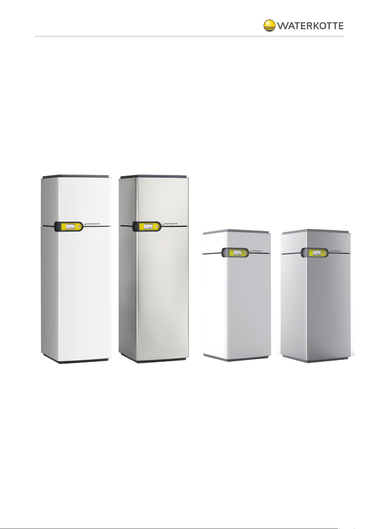
heating system EcoTouch Ai1 Geo
domestic hot water tank
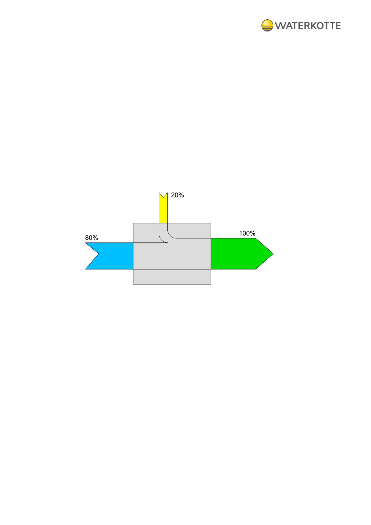
2.1 Description
Figure 1: Energy share when using a geothermal energy pump
The WATERKOTTE heating central EcoTouch Ai1 Geo uses a heat pump as heat
generator. At the heat source side the medium is cooled down in the vaporizer
about 3 to 4K with the help of this device. The hereby won energy is made usable
for heating purposes by transport through the cooling circle up to a higher temperature level.
Heating energy is given to the medium about the liquefier at the heating side, so a
temperature rise about 5K is reached.
On this way building heating and domestic water heating can be done.
Outside the heating period the heat source installation can be used as heat sink
for the cooling of the building (option natural cooling).
The configuration of the heat source system must be planned in accordance with
the technical information of WATERKOTTE GmbH heat source installation instructions.
Product describtion
21.11.2015
11 / 76
Z20469
Copyright 2013 by: WATERKOTTE GmbH. Subject to changes.
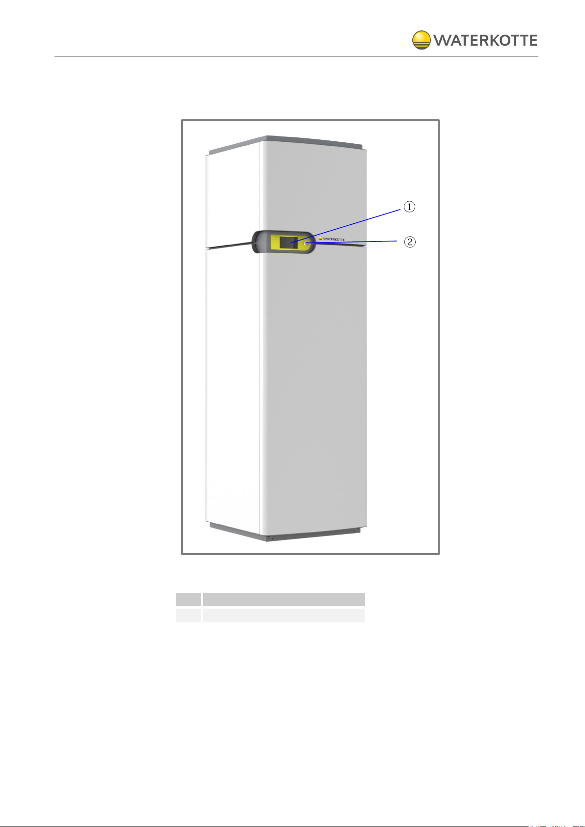
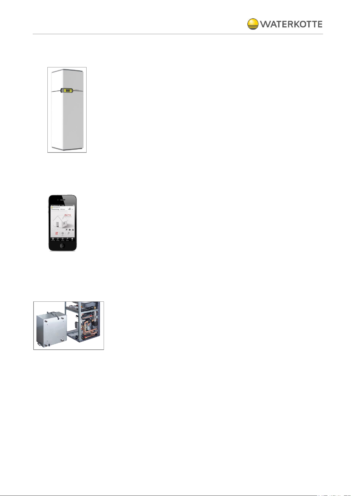
1
Touch Display
2
ON / OFF switch
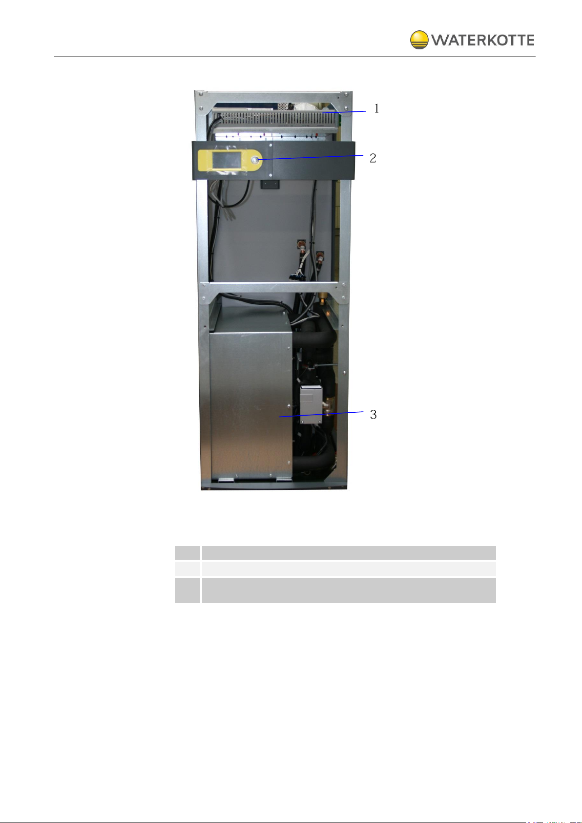
3 Product describtion
3.1 Overview
Figure 2: EcoTouch Ai1 Geo (closed)
Product describtion
21.11.2015
12 / 76
Z20469
Copyright 2013 by: WATERKOTTE GmbH. Subject to changes.
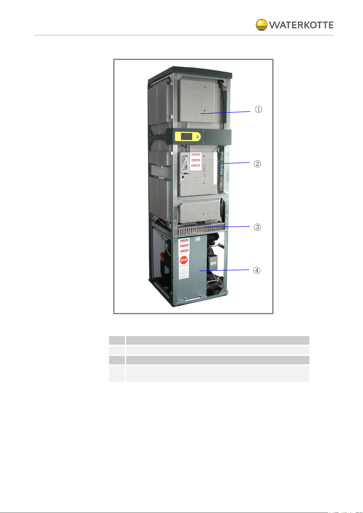
1
Tank for domestic hot water
2
Connecting terminal (400 V – series)
3
Control board (extricable)
4
Heat pump with thermobox (compressor, heat exchanger, expansion valve, ...)
Figure 3: EcoTouch Ai1 Geo (open)
Product describtion
21.11.2015
13 / 76
Z20469
Copyright 2013 by: WATERKOTTE GmbH. Subject to changes.
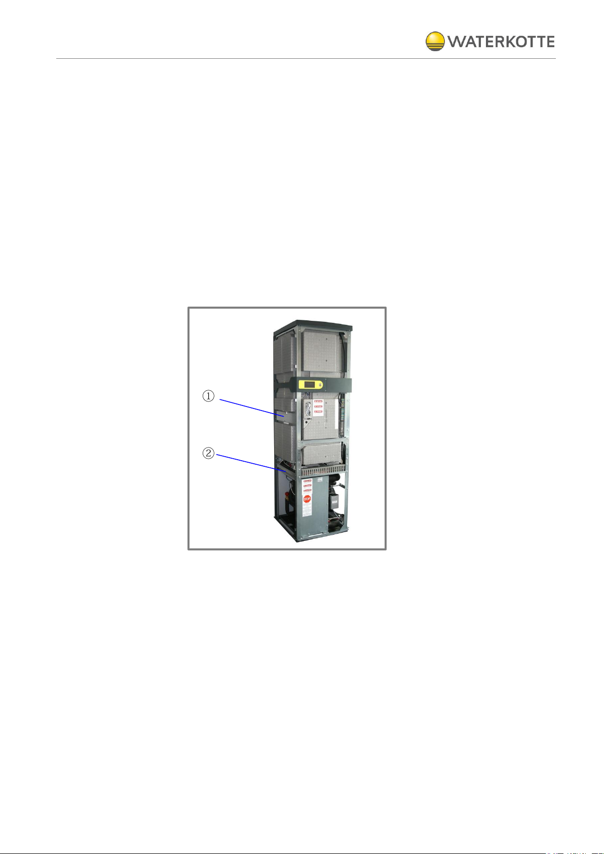
1
Anschlussklemmen, Schalttafel
2
Control element / ON / Off -switch
3
Heat pump element with thermo box (compressor, heat exchanger
expansion valve, ...)
Illustration 4: EcoTouch DS 5018 Ai (open)
Components and installation
21.11.2015
14 / 76
Z20469
Copyright 2013 by: WATERKOTTE GmbH. Subject to changes.
4 Components and installation
4.1 Heating system EcoTouch Ai1 Geo
All components of the heating system are mounted in a protective steel plate
housing which is intended for installation inside. The base frame consists of a
bent, thick-walled sheet steel. Together with the rear panel frame, which also
consists of a thick-walled sheet steel, it forms a unit. Side panels, cover, front and
the tilt-mounted, ergonomic control panel can be removed.
All housing parts are optionally available in high-gloss white or stainless steel finish. Sound insulation ensures low noise emissions.
4.2 Structure
The EcoTouch Ai1 Geo series is a complete hot water heating system with integrated central hot water supply, consisting of heat generator (heat pump), heat
source system, electrical heating element for start up and stand by, electrical control, domestic hot water tank made (not DS 5018) of stainless steel (204 l, insolated with integral foam), complete electrical and control engineering, touch display
with Easy-Con Software, smartphone control via Easy-Con Mobile software, diagnosis system.
4.2.1 Heat pump module
All hydraulic connections are placed on the back side. All modules in the framework are law vice fitted with removable, heat and sound insulated housing, color
signal white (RAL 9003) or stainless steel.
The heat pump module includes the entire hydraulic technik.
The thermobox consisting of compressor and heat exchanger is enclosed and
includes a "Silenter" for vibration damping.
This ensures low operatioin noise of about 43 dB (A) - 45 dB (A), depending on
model.
For service purposes, the thermobox can be completely dismantled (see figure).

Components and installation
21.11.2015
15 / 76
Z20469
Copyright 2013 by: WATERKOTTE GmbH. Subject to changes.
4.2.2 Compressor
4.3 Electrical equipment
The compressor features a fully hermetic design in approved leading scroll technology (fig. left). Evaporator and condenser are designed as soldered stainless
steel plate packs with reverse flow circuits, according to state-of-the-art development, tailored to the new non-flammable safety refrigerants that will be required by
law in the future. In combination with ester oil (biodegradable), this guarantees optimum lubrication conditions, low friction losses and therefore the highest possible
life expectancy for the compressor according to the latest industrial research findings.
The cooling circuit is designed in accordance with the relevant safety regulations.
Manufacturing quality is carried out based on ISO 9000ff, supplemented by an automated computer-monitored quality test (pressure stress and helium leak test) in
addition to inspection of all parameters in a subsequent trial run.
The electrical connections are made via the internal terminal (on the construction
profile). The implementation of the electrical cable is carried by the rear wall (with
the strain relief).
The internal terminal connects the entire sensor, all queries, all relay outputs, digital circuit, the compressor and the electrical heating element. The WATERKOTTE
WWPR-controller is supplied with a control panel mounted on the 24 VAC transformer.
An integrated web interface is available for remote monitoring via the Internet.
4.3.1 Electrical resistance heating
Located in the heating flow, power 6 kW. Used to support initial heating in the
winter and during the standby function; automatic or independent control via the
built-in mechanical thermostats.
4.3.2 Domestic hot water heating system
Consisting of: heating circulation pump (speed-controlled / energy class A), air
separator with automat. air diverter, connections for heating flow and return are fitted externally to facilitate installation in the rear panel frame.
4.3.3 Natural cooling
The components of the natural cooling are factory fitted.
4.3.4 Heat source
Consisting of: heating circulation pump speed-controlled / energy class A, connections for heating flow and return are fitted externally to facilitate installation in
the rear panel frame.

Components and installation
21.11.2015
16 / 76
Z20469
Copyright 2013 by: WATERKOTTE GmbH. Subject to changes.
4.3.5 Electronic heat pump control
The heat pump control (control panel is pictured) is included in the delivery scope
of the WATERKOTTE heat pump.
Use in other than WATERKOTTE heat pumps will void any warranty claim.
The control is used to control and monitor heating systems that are operated with
WATERKOTTE compact heat pumps according to technical guidelines of
WATERKOTTE Wärmepumpen GmbH.
The following tasks are performed: everything to do with regulation (depending on
the external temperature with pilot room guidance), control, monitoring, selfdiagnosis, saving of data in cases of breakdown.
WATERKOTTE explicitly states that function warranty will become void if used on
systems not approved by WATERKOTTE. Any liability for consequential damages
due to incorrect function within these systems shall be explicitly excluded.
4.3.6 Sensors
4.3.7 COP counter
4.3.8 Options
Info: Technical details, operation and warning messages (see
for Heat pump control)
.
Operating manual
The control's sensor system consists of: Pressure transmitter for evaporation and
condensation pressure, sensors for temperature detection in all circuits, external
wall sensor in accessories kit, pilot room sensor and hot water sensor (optional).
A WATERKOTTE COP counter is already integrated in the heat pump control. For
additional information, please refer to
Operating manual for Heat pump control.
Mixer accessories: sensor, additional control module.
Expansion kit: for pool heating, thermal use of solar energy, mixer circuits.
Pool accessories: sensor, 3-way-valve, additional control module.
Buffer tank: standard tank.
Heat source accessories: heat exchanger for ground water, flow rate monitoring,
antifreeze concentrate, heat source distributor.
Solar accessories: sensor, additional control module, heat exchanger, solar collectors.
Heating: underfloor heating system, underfloor heating head station, distribution
cabinet, convectors.
Heat pump accessories: Digital soft starter (for retrofitting at 3 x 400V compressor
design).

Components and installation
21.11.2015
17 / 76
Z20469
Copyright 2013 by: WATERKOTTE GmbH. Subject to changes.
4.4 Hydraulical equipment
4.4.1 Domestic water heating technology
Heat exchanger made in high vacuum solder technology that works for indirect
water heating up to 60°C.
4.4.2 Domestic hot water tank (not DS 5018)
In system-specific design, Inhalt 204 Liter, test pressure 12 bar. tank made of
stainless steel, insulated with Neopor RG, (heat loss < 80 W at 60 °C). Connections for cold and hot water in the rear. An automatic legionella protection circuit
ensures hygienic quality of drinking water.
Note: Accessories as fittings, additions and security group and expansion vessel
are not included. They are optionally available.
4.4.3 Heat transfer medium
The unit may only operate with heat transfer media approved by Waterkotte.
These are Water-Glycol-mixes:
4.4.4 Use of passive Cooling
25 Vol. % Waterkotte-Ethylen-Glycol or
33 Vol. % Waterkotte-Propylen-Glycol
The heat source circulation and the heat use circulation are connected hydraulically. Therefore, both systems run with the same heat transfer medium.
Transport
21.11.2015
18 / 76
Z20469
Copyright 2013 by: WATERKOTTE GmbH. Subject to changes.
5 Transport
For easy transport the heat pump will be supplied in three packaging: hot water
tank (not DS 5018), heat pump unit and housing.
Exercise particular caution when transporting the units. Since the unit weighs
208 kg up to 225 kg at least two people are required for transport. Do not use
the packaging straps to carry the unit. Wear protective gloves for unpacking
and transporting the unit to prevent hand injuries from cooling fins or other
parts.
Observe the transport information on the packaging.
Observe the specified storage requirements.
The units may not be stacked.
Machine may only be lifted at the provided attachment points, ref. to photo:
Pos. 1 und Pos. 2.
Figure 5: Attachment points (left side)
Machine may only be transported in upright position.
Ensure proper disposal of packaging materials. Packaging materials, such as
nails or other metal or wooden parts, may cause injuries.
Please also read chapter "General safety information“.

Transport
21.11.2015
19 / 76
Z20469
Copyright 2013 by: WATERKOTTE GmbH. Subject to changes.
5.1 Transport to installation site
Units of the EcoTouch ai1 Geo / DS 5018 series are delivered ready-to-connect
with separate metal cladding. For transport purposes, the metal cladding and the
heat pump are delivered in one carton on a palette. During transport it must be
ensured that appropriate means of transport are used (lift truck, transport rollers,
handcart).
Even at the installation site the devices are mounted above each other.
Unit must be transported upright!
Transport in tilted position (45°) is permitted only temporarily during insertion.
Horizontal transport results in oil displacement in compressor and can cause
damage during start-up.
After carton is removed or opened it is not permitted to tilt the unit by applying
pressure to the pipelines or housing enclosure; this could result in bent housing
parts and pipelines.
Installation
21.11.2015
20 / 76
Z20469
Copyright 2013 by: WATERKOTTE GmbH. Subject to changes.
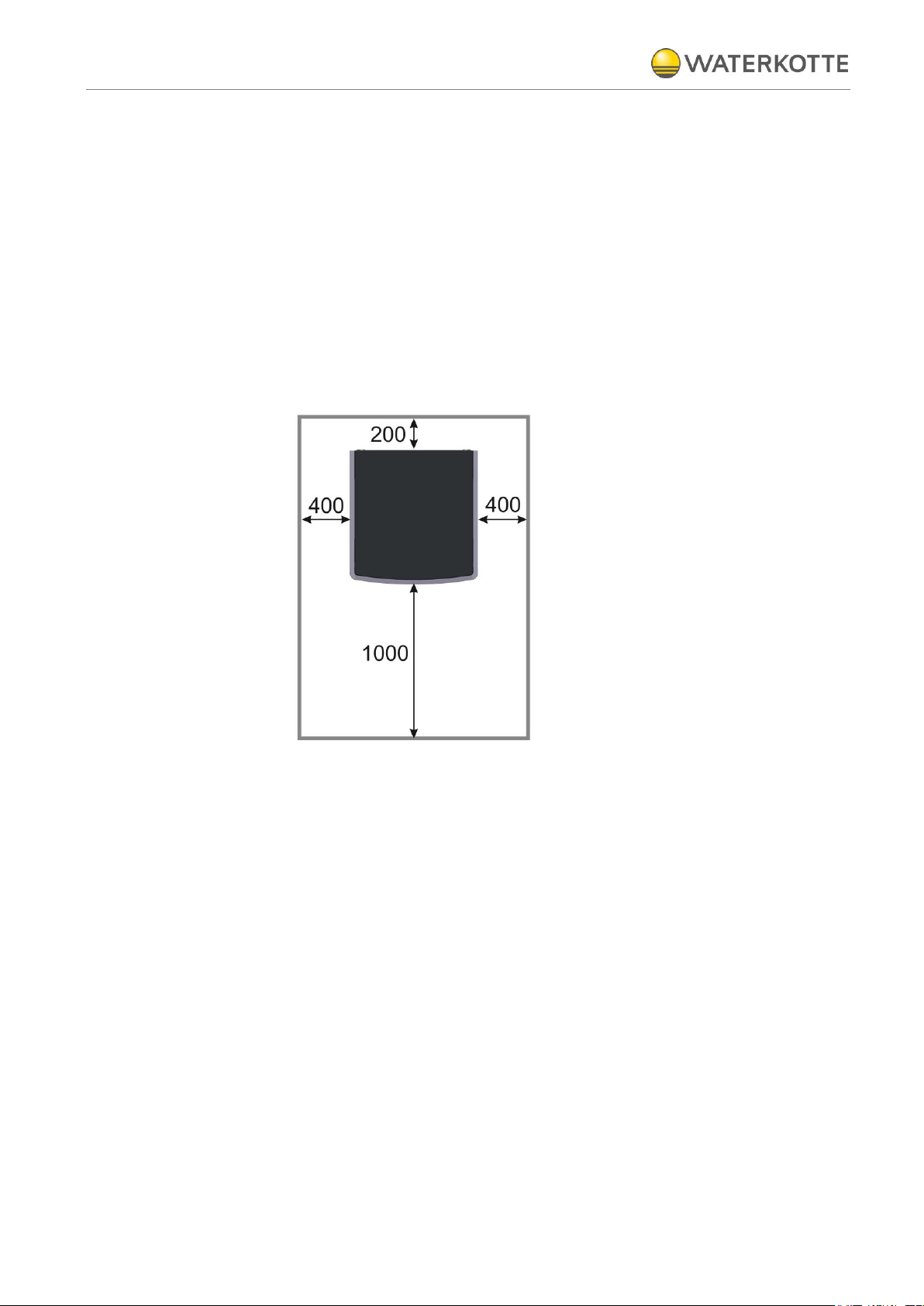
6 Installation
Installation of the heat pump must be performed on a flat and horizontal sur-
face.
We recommend a concrete base.
Recommendation:
Wall clearance left, right and on top must be at least 400 mm.
Wall clearance in rear must be at least 200 mm.
Wall clearance in front: at least 1.000 mm
Figure 6: Recommendation - wall clearances
6.1 Environmental conditions for installation
The room must be dry. Room temperature should be between
+10 °C and +30 °C.
To facilitate maintenance, the use of a base plate is recommended. The housing
frame is to be completely supported. If support is only provided at points, operating noise increases. To compensate for minor unevenness, we recommend use of
an approx. 10 mm thick rubber mat. Acoustics in installation rooms with rigid walls
can noticeably increase operating noise.
Counter measure: acoustic insulation of one of the opposite wall or ceiling surfaces.
Installation
21.11.2015
21 / 76
Z20469
Copyright 2013 by: WATERKOTTE GmbH. Subject to changes.
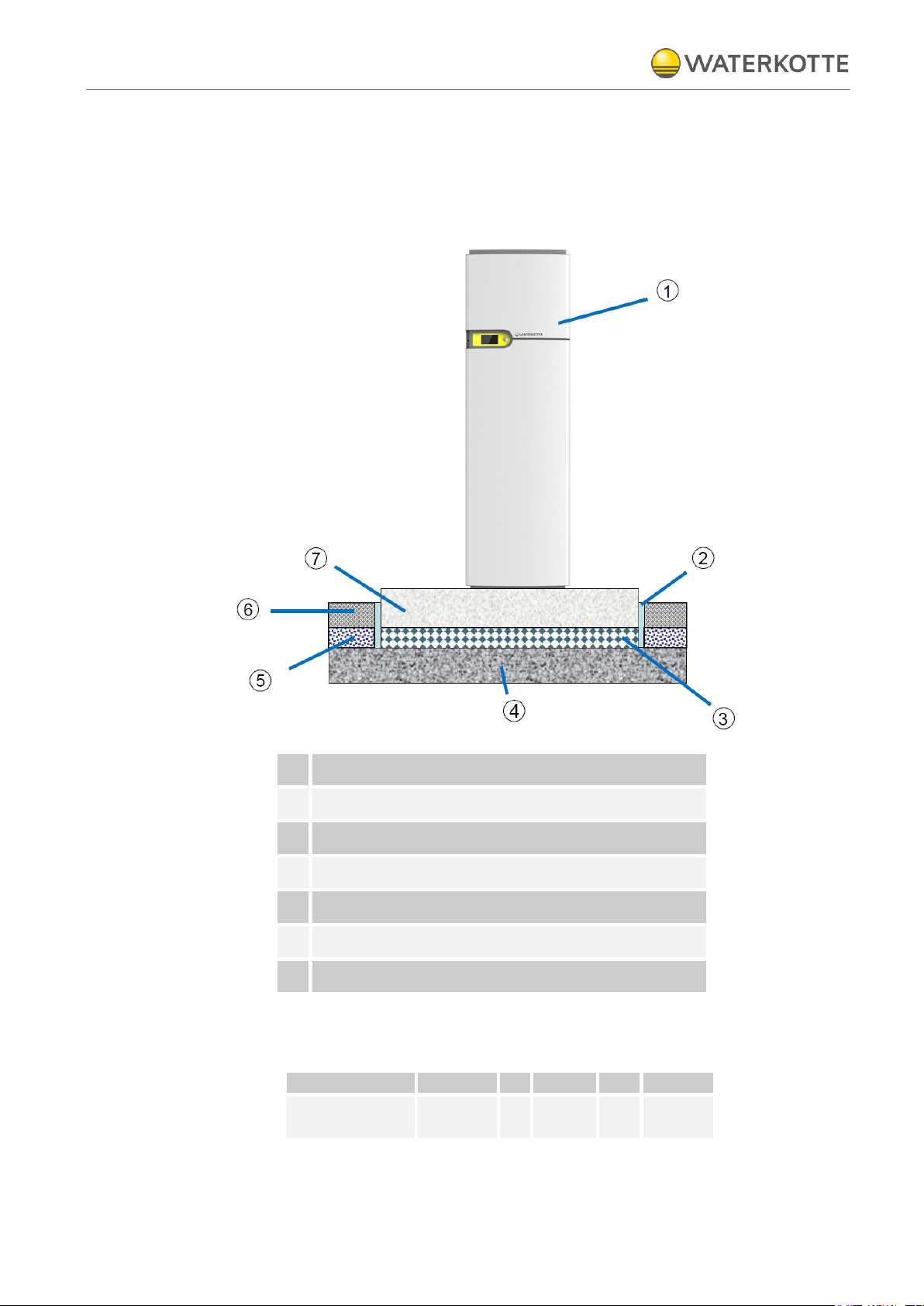
1
Heat pump
2
Insulation strip (polyethylen / PE)
3
Insulation material (3 layer, polyurethan rubber)
4
Supporting subsurface
5
Insulation material
6
Screed
7
Concrete plinth
Series
Width
x
Depth
x
High
ECOTouch
Ai1 Geo
850
x
880 x 150
6.2 Creating the foundation and installing heat pump
- with best possible structure-borne noise insulation
6.2.1 Installation of heat pumps
Dimensions concrete plinth (mm)
Installation of heat pump and domestic hot water tank
21.11.2015
22 / 76
Z20469
Copyright 2013 by: WATERKOTTE GmbH. Subject to changes.
Item No
Description
EcoTouch
Ai1 Geo
EcoTouch
DS 5018 Ai
Z13122
Outdoor wall mounted sensor (accessories box heat pump)
1
1
Z18595
Screw (fillister head) (M8 x 16 ISO 7380 galvanized) for fixing of the
construction
16
--
Z20223
Screw for Wüplast W1423 4x12 galvanized, cross slot
2
--
Z13679
Gasket 30.5 x 19.5 x 2 mm Klingersil for 1“, connection of the tank
2
--
Z14872
Gasket 38 x 27.5 x 2 mm Teadit TF1570 for 11/4“
4
--
Z13113
Allen screw M 6 x 16 DIN 933 8.8 galvanized (mounting of the 400 V /
230 V terminal)
2
--
Z13113
Allen screw M 6 x 16 DIN 933 8.8 galvanized (mounting of the 230 V
terminal)
2
--
Z20240
Installation manual EcoTouch Ai1 Geo
1
1
Z20432
WWPR manual
1
1
Z15312
Installation document: Acceptance and Installation Data
1
1
Z20086
Removing Tool (for the removing of the housing)
1
1
Z13683
Bleeder (upper part, (shut-off device already mounted on the tube),
for installation by connecting the upper tank connection.
1
--
7 Installation of heat pump and domestic hot water tank
7.1 Connection accessories
Installation of heat pump and domestic hot water tank
21.11.2015
23 / 76
Z20469
Copyright 2013 by: WATERKOTTE GmbH. Subject to changes.
2 1
7.2 Installation
7.2.1 Installation of the heat pump module
Transport the heat pump module to the intended site. Align the heat pump module in a horizontal position. To do this, use the set screws for height adjustment
(under the corners of the unit), width across flats 30 mm
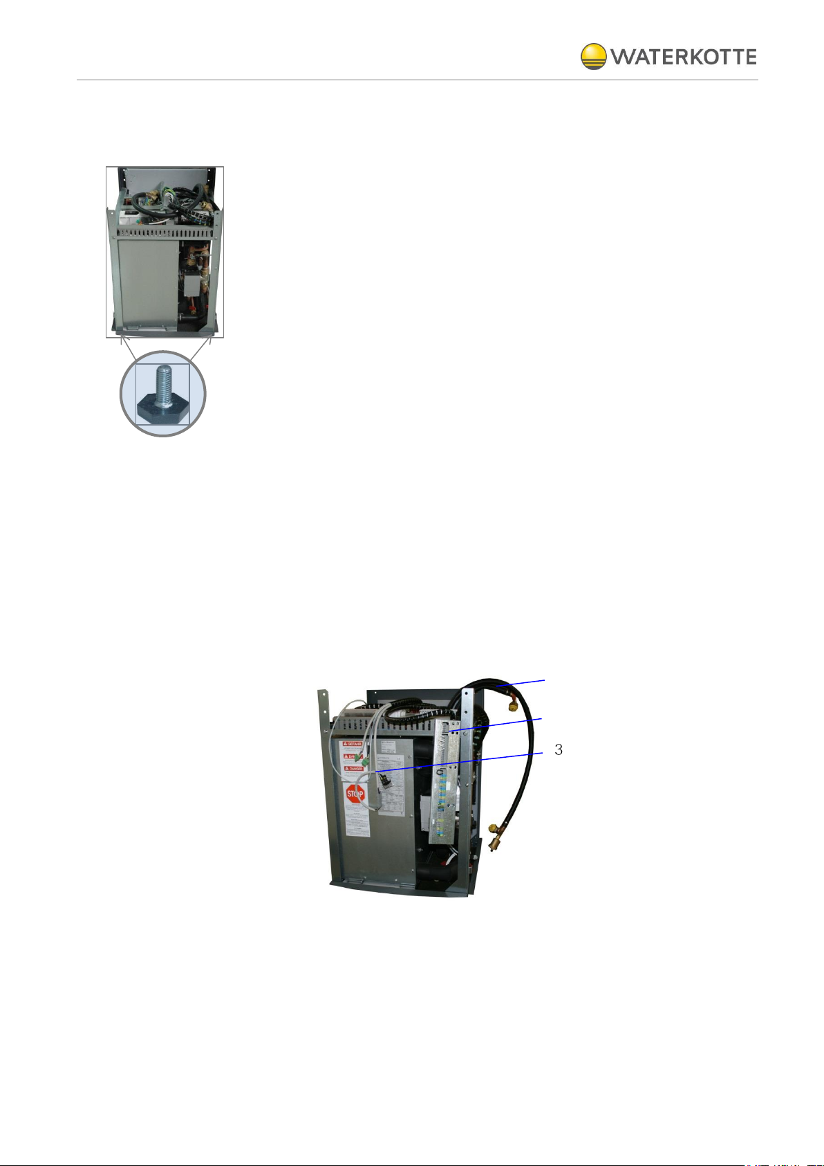
7.2.2 Preparation of the assembly (EcoTouch Ai1 Geo)
After completion of assembly the supply lines have to be accessible. Arrange them
as follows:
Place the connecting tubes (1) of the tank at the side of the unit (right)
Place the terminal strip (2) for the electric connection and the connection of
the display (3) at the front of the unit (right), see photo.
 Loading...