

WATERKOTTE EcoTouch Ai1 Air Planning And Installation
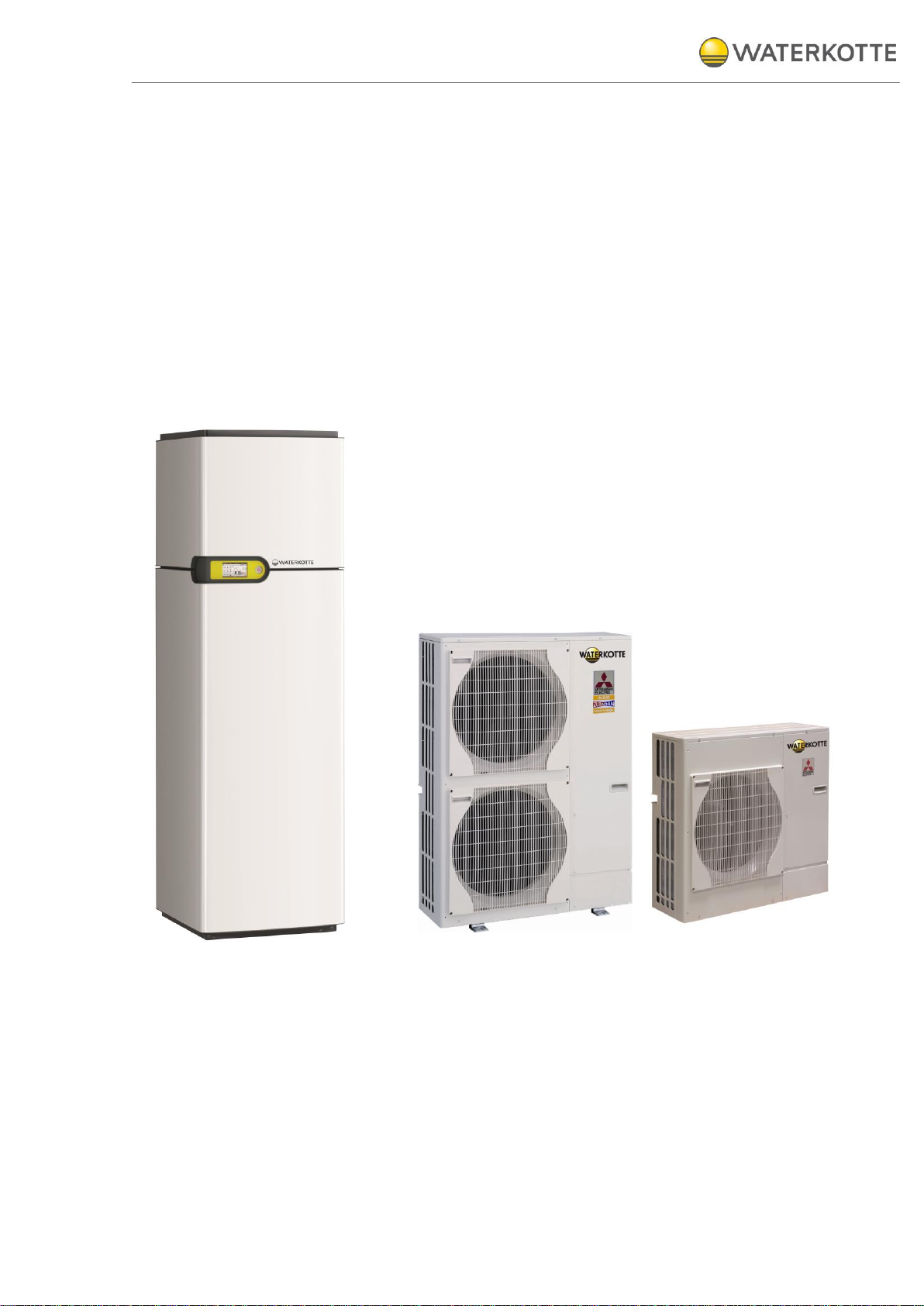
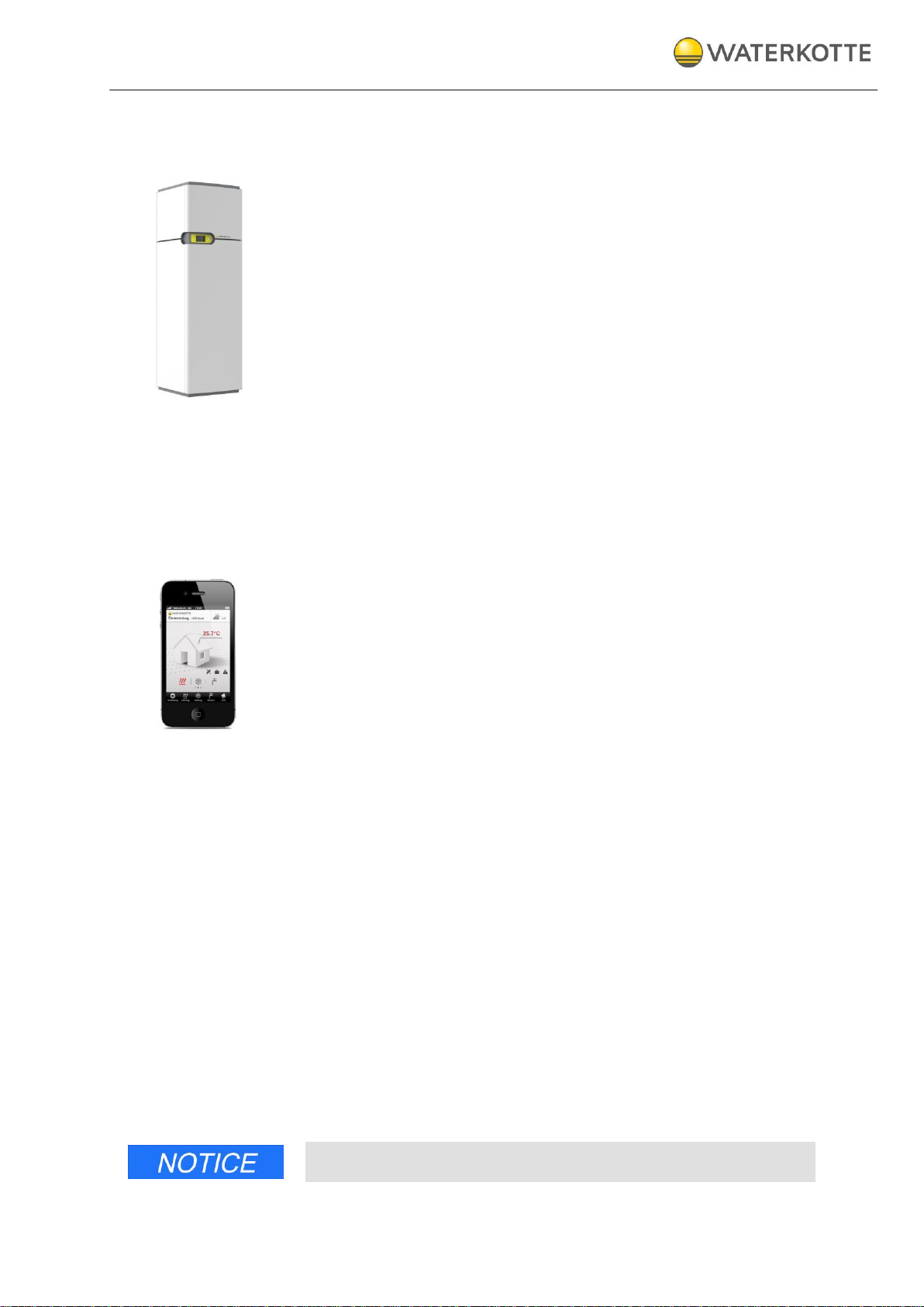
EcoTouch Ai1 Air, Indoor unit
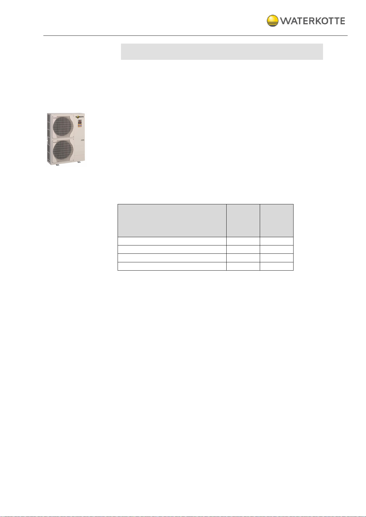
Outdoor units: EcoTouch Ai1 Air
(Zubadan and Power Inverter)
WATERKOTTE GmbH, Gewerkenstraße 15, D-44628 Herne
Tel.: 0049/(0)2323/9376-0, Fax: 0049/(0)2323/9376-99, E-Mail: info@waterkotte.de
Internet: http://www.waterkotte.de
05.06.2015 / Z20655
Planning and installation
EcoTouch Ai1 Air
Zubadan and Power Inverter
Electrical connection types: 230 V, 400 V, 230 V/400 V
Heating station

05.06.2015
2 / 80
Copyright 2013 by: WATERKOTTE GmbH. Subject to changes.
Copyright 2013 by
WATERKOTTE GmbH,
Gewerkenstraße 15, 44628 Herne, Germany
All rights reserved. Reproduction, duplication as well as translation of this
publication, or excerpts therefrom, require prior written approval by
WATERKOTTE GmbH.
Illustrations and diagrams serve as explanatory description and shall not be
used as drawings for construction, offers or installation.
All specifications comply with the state of technology at time of printing; we
reserve the right to make changes that serve technical progress.
This publication has been prepared with all reasonable care.
WATERKOTTE GmbH does not assume any liability for remaining errors or
omissions, or for possible damages.
Note: This symbol mark applies only to countries within the European
Union (EU).
This symbol mark is in compliance with Directive 2002/96/EG, Article 10.
The product has been designed and manufactured with high-quality
materials and components which are suitable for recycling.
This symbol means that electrical and electronic equipment, at the end of
its useful life, shall be disposed of separately from household waste. Please
dispose of this equipment at your designated collection point or local
recycling centre.
In the European Union, different collection systems are available for used
electrical and electronic equipment. Please help us to conserve the environment we live in!
Do not vet R410A into the atmosphere:
R410A is a fluorinated greenhouse gas according to Kyoto Protocol and
has a global warming potential (GWP) of 1975.

05.06.2015
3 / 80
Copyright 2013 by: WATERKOTTE GmbH. Subject to changes.
Content
1 Safety ..................................................................................................................................... 6
1.1 Intended use ...................................................................................................................... 6
1.2 Basic safety precautions .................................................................................................... 6
1.2.1 Keep information available .................................................................................... 6
1.2.2 Before initial use .................................................................................................... 6
1.2.3 Environmental protection ...................................................................................... 7
1.2.4 Modifications and repairs on the heat pump ......................................................... 7
1.3 Hazards ............................................................................................................................. 8
1.4 Operator's duty of care ...................................................................................................... 9
1.5 Other applicable documents .............................................................................................. 9
2 Functional principle of heat pumps ......................................................................................... 10
3 Product description and scope of delivery .............................................................................. 11
3.1 Overview.......................................................................................................................... 11
3.2 Scope of delivery ............................................................................................................ 12
3.2.1 Heat distribution station EcoTouch Ai1 Air .......................................................... 12
3.2.2 Domestic hot water tank ..................................................................................... 12
4 Components and setup ......................................................................................................... 13
4.1 Heat distribution station EcoTouch Ai1 Air ....................................................................... 13
4.2 Construction and Controlling ........................................................................................... 13
4.3 Electronic heat pump control ........................................................................................... 13
4.4 Outdoor unit (heat source) ............................................................................................... 14
4.5 Overview: ECOTouch Ai1 Air ........................................................................................... 14
4.5.1 Connection accessories ...................................................................................... 15
4.6 Sensor system ................................................................................................................. 15
4.7 Heat meter (optional) ....................................................................................................... 15
5 Transport .............................................................................................................................. 16
6 Installation and connection .................................................................................................... 17
6.1 Installation and connection of indoor unit ......................................................................... 17
6.2 Environmental conditions for installation .......................................................................... 18
6.2.1 Installation of the heat pump ............................................................................... 18
6.2.2 Preparation of the assembly ............................................................................... 18
6.2.3 Assembly of the heat pump ................................................................................ 19
6.2.4 Connection tube of the tank (at the top) .............................................................. 20
6.2.5 Connection tube of the tank (bottom).................................................................. 20
6.2.6 Connection terminal ............................................................................................ 21
6.2.7 Installation of the temperature sensor ................................................................ 22
6.2.8 Installation of the Touch Display ......................................................................... 23
6.2.9 Installation of the housing ................................................................................... 24
6.2.10 Removing the housing ........................................................................................ 25
7 Installation and connection .................................................................................................... 26
7.1 Connections (rear) ........................................................................................................... 26
7.2 Connection measurements .............................................................................................. 27

05.06.2015
4 / 80
Copyright 2013 by: WATERKOTTE GmbH. Subject to changes.
8 Installation and connection of outdoor unit ............................................................................. 28
8.1 Selecting a location for outdoor unit ................................................................................ 28
8.1.1 Dimensions of outdoor unit ................................................................................. 29
8.1.2 Clearance for ventilation and operation ............................................................... 30
8.1.3 Mounting on base plate or on the wall ................................................................ 30
8.1.4 Installation and space requirement ...................................................................... 31
8.2 Connection outdoor unit / indoor unit (refrigerant lines) .................................................... 32
8.2.1 Installation of refrigerant lines .............................................................................. 32
8.2.2 Connections indoor unit (refrigerant line) ............................................................. 33
8.2.3 Connections outdoor unit (refrigerant line) ........................................................... 33
8.2.4 Installation of a LOKRING coupling (example) ..................................................... 34
8.2.5 Tube airtight testing method (recommended procedure) ..................................... 36
9 Refrigerant ............................................................................................................................ 37
9.1 Requirements on handling of R410A refrigerant ............................................................... 37
9.2 Safety information on handling of refrigerant .................................................................... 37
9.3 Refrigerant charge and additional charge – EcoTouch Ai1 Air (Zubadan) ......................... 38
9.4 Refrigerant charge and additional charge – EcoTouch Ai1 Air (Power Inverter) .............. 39
9.5 Charging refrigerant circuit ............................................................................................... 40
9.5.1 Adding refrigerant ............................................................................................... 41
9.5.2 Insulation ............................................................................................................ 41
10 Electrical work ....................................................................................................................... 42
10.1 Electrical connection outdoor unit .................................................................................... 43
10.2 Electrical connection indoor unit ...................................................................................... 44
10.2.1 Connection Temperature sensor ......................................................................... 44
10.2.2 Connection Touch Display .................................................................................. 44
10.2.3 Installing external wall sensor .............................................................................. 44
10.2.4 Adjustment of the electrical heating element ....................................................... 44
10.3 Connection diagram ........................................................................................................ 45
10.3.1 EcoTouch Ai1 Air Zubadan and Power Inverter: Overview clamps (400 V) .......... 45
10.3.2 EcoTouch Ai1 Air Zubadan and Power Inverter: Overview clamps (230 V) .......... 46
10.3.3 EcoTouch Ai1 Air Zubadan and Power Inverter: Overview clamps
(Compressor 230 V / Electrical resistance heating 400 V) ................................... 47
10.3.4 EcoTouch Ai1 Air Zubadan and Power Inverter: Overview clamps X1 (all models)48
10.3.5 EcoTouch Ai1 Air Zubadan and Power Inverter: Overview clamps X2 (all models)49
10.3.6 EcoTouch Ai1 Air Zubadan and Power Inverter: Overview clamps X4 (all models)50
10.3.7 EcoTouch Ai1 Air Zubadan and Power Inverter: Input (400 V) ............................. 51
10.3.8 EcoTouch Ai1 Air Zubadan and Power Inverter: Input (230 V) ............................. 52
10.3.9 EcoTouch Ai1 Air Zubadan and Power Inverter: Input (Compressor 230 V /
Electrical resistance heating 400 V) ..................................................................... 53
10.3.10 EcoTouch Ai1 Air Zubadan and Power Inverter: Electric heating insert (400 V).... 54
10.3.11 EcoTouch Ai1 Air Zubadan and Power Inverter: Electric heating insert (230 V).... 55
10.3.12 EcoTouch Ai1 Air Zubadan and Power Inverter: Control power (all models) ........ 56
10.3.13 EcoTouch Ai1 Air Zubadan and Power Inverter: Control source and heating
pump (400 V and 230 V) .................................................................................... 57
10.3.14 EcoTouch Ai1 Air Zubadan and Power Inverter: Switched output extern (400 V
and 230 V) .......................................................................................................... 58
10.3.15 EcoTouch Ai1 Air Zubadan and Power Inverter: Digital output extern (400 V
and 230 V) .......................................................................................................... 59
10.3.16 EcoTouch Ai1 Air Zubadan and Power Inverter: Analoque signals extern (400 V

05.06.2015
5 / 80
Copyright 2013 by: WATERKOTTE GmbH. Subject to changes.
and 230 V) .......................................................................................................... 60
10.3.17 EcoTouch Ai1 Air Zubadan and Power Inverter: Expansion valve, BUS
and Display (230 V and 400 V) ........................................................................... 61
10.3.18 EcoTouch Ai1 Air Zubadan and Power Inverter: Intern control board (400 V
and 230 V) .......................................................................................................... 62
10.3.19 EcoTouch Ai1 Air Zubadan and Power Inverter: WWPR 2 (400 V and 230 V) ..... 63
10.4 DIP switch of motherboard (indoor unit) ........................................................................... 64
11 Silent Mode (option) .............................................................................................................. 65
11.1 Connecting „
Silent Mode
“ ................................................................................................ 66
11.2 Silent mode (only the fan speed reduction) ...................................................................... 67
11.3 Step mode (speed reduction of fan and compressor) ...................................................... 67
12 Start-up ................................................................................................................................ 68
12.1 Pre-startup checks .......................................................................................................... 68
12.2 Initial start of the heat pump ............................................................................................ 71
12.3 Control of entire operation ............................................................................................... 71
12.4 Turning heat pump off ..................................................................................................... 72
12.5 Taking heat pump out of operation for extended period .................................................. 72
13 Defrost operation .................................................................................................................. 72
13.1 Start ................................................................................................................................ 72
14 Maintenance and care ........................................................................................................... 73
15 Technical Data ...................................................................................................................... 74
15.1 EcoTouch Ai1 Air (Zubadan) ............................................................................................ 74
15.2 EcoTouch Ai1 Air (Power Inverter) .................................................................................... 75
16 Connection diagram .............................................................................................................. 76
16.1 EcoTouch Ai1 Air with underfloor heating (Basic circuit diagram) ..................................... 76
16.2 EcoTouch Ai1 Air with underfloor heating and single room control (Basic circuit diagram) 76
16.3 EcoTouch Ai1 Air with radiators or fan convectors (Basic circuit diagram) ....................... 77
16.4 EcoTouch Ai1 Air with hydraulic filter (Basic circuit diagram) ............................................ 77
16.5 Overview EcoTouch Ai1 Air .............................................................................................. 78

Safety
05.06.2015
6 / 80
Copyright 2013 by: WATERKOTTE GmbH. Subject to changes.
1 Safety
1.1 Intended use
Your WATERKOTTE heat pump of the EcoTouch Ai1 Air series is used for
space heating and cooling, and heating of domestic water.
An outdoor unit, which is coupled to a heat source (air) that is available
year-round, serves as heat generator.
Project planning of the heat source system must be performed in compliance with the technical information provided by WATERKOTTE for layout of
heat source systems.
Heat pump shall only be turned on after the refrigerant connections are
completely filled, and the other hydraulic circuits are completely filled and
vented, and all electrical connections are properly completed.
Commissioning may only be carried out by trained professionals. Damages
caused by non-compliance with above mentioned items are not covered by
the warranty (see enclosed Exclusion of Warranty).
1.2 Basic safety precautions
1.2.1 Keep information available
In addition to the operating manual, also furnish operating instructions in
terms of Labour Protection Law and Work Equipment ordinance.
Keep all safety and operating signs on the heat pump in fully legible condition at all times. Replace damaged or illegible signs immediately.
1.2.2 Before initial use
Before initial use of your WATERKOTTE heat pump, familiarise yourself with:
Operating and control elements of your WATERKOTTE heat pump
Equipment of heat pump
Operation of heat pump
Immediate surroundings of heat pump
Safety devices of heat pump
Before initial start, perform the following work:
Ensure that all safety devices are installed and function as intended.
Check heat pump for visible damage. Remedy any detected defects
immediately. Heat pump must be in perfect condition during operation!
Ensure that only authorised personnel is in the work area of the heat
pump and that no other persons are endangered when heat pump is
started.
Remove all objects and other materials that are not required for opera-
tion of the heat pump from the work area of the heat pump.

Safety
05.06.2015
7 / 80
Copyright 2013 by: WATERKOTTE GmbH. Subject to changes.
1.2.3 Environmental protection
Observe the regulations regarding waste avoidance and proper waste
recycling or disposal when performing any kind of work on and with the
heat pump.
Ensure that particularly during installation and maintenance work, as well
as when placing out of operation, pollutants such as grease, oil, refrigerant, solvent- containing cleaning fluids, etc. do not contaminate the
ground or enter the sewer system!
These materials must be collected, stored, transported and disposed of
in appropriate containers.
1.2.4 Modifications and repairs on the heat pump
For safety reasons, no unauthorised modifications shall be performed on
the heat pump.
Thus, all intended modifications are subject to written approval by
WATERKOTTE.
Use only original spare parts from WATERKOTTE.
Original spare parts are specially designed for your heat pump. Externally
procured parts provide no guarantee that they are designed and manufactured in compliance with relevant usage and safety requirements.
Parts and special equipment not delivered by WATERKOTTE are not approved for use on the heat pump.
Safety
05.06.2015
8 / 80
Copyright 2013 by: WATERKOTTE GmbH. Subject to changes.
1.3 Hazards
Observe the following points to avoid life-threatening injuries and damages
to the heat pump during operation:
Warning! Risk of electric shock!
Do not use water or other liquids to clean the unit!
Keep all electrical supply units locked at all times!
Any work on the electrical equipment of the heat pump shall only be performed by professional electricians!
Discharging refrigerant can cause severe personal injury (suffocation or hypothermia)!
Avoid contact with refrigerant!
Note the minimum volume of the installation room and consider the type of
the refrigerant (EN 378-1).
Risk of burns!
During operation, surface temperatures (compressor and pressure line) can
climb above 100 °C or drop below 0 °C.
Do not remove housing cover during operation!
Allow heat pump to cool down before removing cover.
Risk of injury!
Risk of chemical burns when skin comes in direct contact with lubricant
leak.
Wear suitable clothing when performing maintenance work on the heat
pump!
Electrostatic charge!
Electronic components can be damaged by electrostatic processes.
Ground yourself before touching electronic components.
Risk of total loss!
Repeated restart of heat pump can result in total loss!
In case heat pump breaks down, an inspection by qualified and authorised
personnel must be performed before restart.

Safety
05.06.2015
9 / 80
Copyright 2013 by: WATERKOTTE GmbH. Subject to changes.
1.4 Operator's duty of care
Your WATERKOTTE heat pump has been designed and built on the basis
of a risk analysis and after careful selection of standards to be observed.
Thus, your heat pump is state-of-the-art and provides for maximum safety.
In practice, however, this safety can only be ensured by taking all necessary
measures. As operator of the heat pump, it is your responsibility to plan
these measures and oversee their implementation.
You must ensure that:
The heat pump is only used as intended (see also chapter 1.1,
The heat pump is only operated in perfect, fully functional condition and
The operating manual is available in perfect condition at the heat pump
The heat pump is operated, maintained and repaired only by properly
„Intended use“).
safety devices are checked regularly to ensure that they are working
properly.
at all times.
qualified and authorised personnel.
None of the safety and warning notices on the heat pump are removed
or damaged.
1.5 Other applicable documents
Installation manual: Air-Conditioner
Zubadan : Air-Conditioners PUHZ-SHW HA
Power Inverter : Air-Conditioners PUHZ-SW HA..
Operating manual: WWPR WATERKOTTE heat pump controller.
Functional principle of heat pumps
05.06.2015
10 / 80
Copyright 2013 by: WATERKOTTE GmbH. Subject to changes.
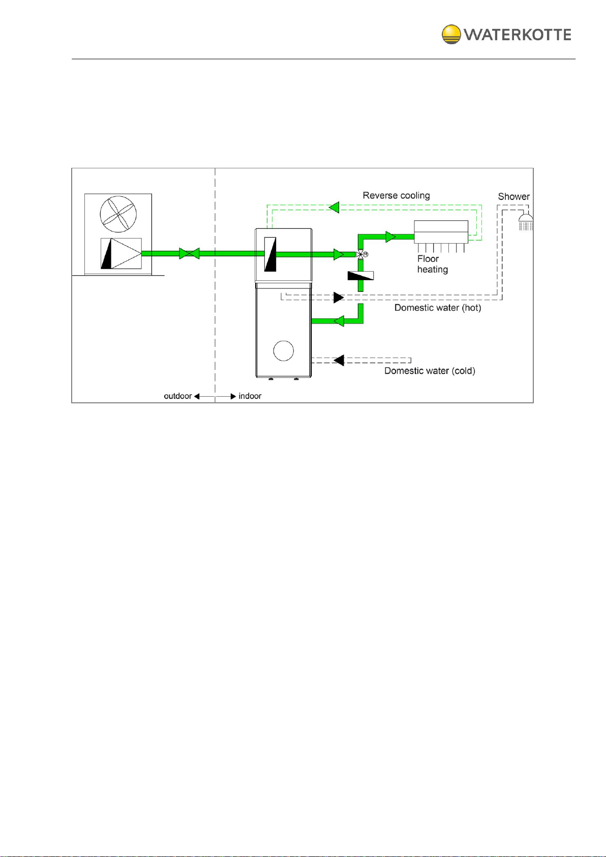
2 Functional principle of heat pumps
The heat pump is used to produce thermal energy for space heating and
domestic water heating. The medium used as heat source
is air.
By means of reverse cooling it is also possible to cool a building.
Figure 1: Heating system with domestic hot water production and heat source air
To utilise air as thermal energy and for domestic water heating in your
home, you need the following:
Outdoor unit.
Indoor unit with domestic hot water tank (not WPQLN(i)) and heat distri-
bution station.
Buffer tank (only in connection with fan convector, radiators or under-
floor heating with single room control).

Product description and scope of delivery
05.06.2015
11 / 80
Copyright 2013 by: WATERKOTTE GmbH. Subject to changes.
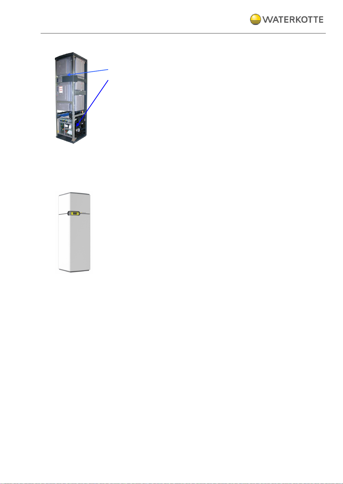
1
Touch display
2
Power switch
3
Outdoor unit
3 Product description and scope of delivery
3.1 Overview
Heat distribution station (indoor unit) Heat source (outdoor unit)
with domestic hot water tank
Figure 2: Function modules of EcoTouch Ai1 Air
Product description and scope of delivery
05.06.2015
12 / 80
Copyright 2013 by: WATERKOTTE GmbH. Subject to changes.
3.2 Scope of delivery
The indoor unit is delivered in two parts:
The top part is the domestic hot water tank.
The bottom part contains the necessary heating technology
(heat distribution station)
3.2.1 Heat distribution station EcoTouch Ai1 Air
The heat distribution station consists of:
Condenser
Air separator
6 kW electrical heating element
Heating pump
Electrical switchboard
Three-way valve
WATERKOTTE controller (space heating-cooling-domestic hot water)
Connections between tank and heat distribution station
Outdoor temperature sensor
3.2.2 Domestic hot water tank
The domestic hot water tank contains:
Domestic hot water sensor
Straight-tube heat exchanger
Cold water connector
Components and setup
05.06.2015
13 / 80
Copyright 2013 by: WATERKOTTE GmbH. Subject to changes.
4 Components and setup
4.1 Heat distribution station EcoTouch Ai1 Air
All components of the heat distribution station are mounted in a protective
steel plate housing which is intended for setup inside. The base frame
consists of a edged, thick-walled sheet steel. Together with the rear panel
frame – which also consists of thick-walled sheet steel – it forms a unit.
Side panels, cover, front and the tilt-mounted, ergonomic control panel
can be removed.
All enclosure components are reliably and permanently protected by
powder-coating and stove enamel finish.
The domestic hot water tank has a 204 l capacity, is composed of stainless
steel and is completely insulated.
4.2 Construction and Controlling
The EcoTouch Ai1 Air series is a complete hot water heating system with
integrated central hot water supply, consisting of heat generator (heat
pump), heat source system, electrical heating element for start-up and
stand by, electrical control, domestic hot water tank made of stainless steel
(204 l, insolated with integral foam), complete electrical and control engineering, touch display with Easy-Con Software, smartphone control via
Easy-Con Mobile software, diagnosis system.
All hydraulic connections are placed on the back side. All modules in the
framework are law vice fitted with removable, heat and sound insulated
housing, color signal white (RAL 9003) or stainless steel.
4.3 Electronic heat pump control
The heat pump control is included in the delivery scope of the
WATERKOTTE heat pump.
Use in other than WATERKOTTE heat pumps will void any warranty claim.
The control is used to control and monitor heating systems that are operated with WATERKOTTE compact heat pumps according to technical guidelines of WATERKOTTE Wärmepumpen GmbH.
The following tasks are performed: everything to do with regulation (depending on the external temperature with pilot room guidance), control,
monitoring, self-diagnosis, saving of data in cases of breakdown.
WATERKOTTE explicitly states that function warranty will become void if
used on systems not approved by WATERKOTTE. Any liability for conse-
Components and setup
05.06.2015
14 / 80
Copyright 2013 by: WATERKOTTE GmbH. Subject to changes.
EcoTouch
Ai1 Air
(Zubadan)
EcoTouch
Ai1 Air
(Power
Inverter)
Heat distribution
•
•
Domestic hot water tank 204 Liter
•
•
Outdoor unit Zubadan
•
Outdoor unit Power-Inverter
•
quential damages due to incorrect function within these systems shall be
explicitly excluded.
Info: Technical details, operation and warning messages (see
manual for Heat pump control).
4.4 Outdoor unit (heat source)
Split design with inverter technology (ZUBADAN or Power Inverter)
Optimised defrost function
Pre-charged with R410A
Euro flare connectors 5/8“ and 3/8“ or 1/2“ and 1/4"
4.5 Overview: ECOTouch Ai1 Air
(• included in delivery)
Operating
Components and setup
05.06.2015
15 / 80
Copyright 2013 by: WATERKOTTE GmbH. Subject to changes.
Heat
pump
Quantity
Item no.
Description
5008 /
5011
5014
1
Z16981
Lokring for copper tube 10x1 mm
5008 /
5011
5014
1
Z16862
Euro-Flare-fittings 3/8“ with Lokring connection for copper tube 10x1 mm (3/8“)
5008 /
5011
5014
3
Z16982
Stabilisation insert for copper tube 10x1 mm
5008 /
5011
5014
1
Z16864
Lokring for copper tube 16x1 mm
5008 /
5011
5014
1
Z16863
Euro-Flare-fittings 3/8“ with Lokring connection for copper tube 16x1 mm (3/8“)
5008 /
5011
5014
3
Z16983
Stabilisation insert for copper tube 16x1 mm
5004/
5006
1
Z18106
Reducing adapter 10x1 mm for Cu-Rohr, to 6,35x0,8 mm
5004/
5006
1
Z18110
Euro-Flare-fittings
1/4“
with Lokring connection for copper tube
6,35x0,8 mm (1/4“)
5004/
5006
1
Z16982
Stabilisation insert for copper tube 10x1 mm
5004/
5006
2
Z18108*
Stabilisation insert for copper tube
6,35x0,8 mm
5004/
5006
1
Z18107
Reducing adapter for 16x1 mm Cu-Rohr, to 12,7x0,8 mm
5004/
5006
1
Z18111*
Euro-Flare-fittings
1/2
with Lokring connection for copper tube
12,7x0,8 mm (1/2“)
5004/
5006
1
Z16983*
Stabilisation insert for copper tube
16x1 mm
5004/
5006
2
Z18109*
Stabilisation insert for copper tube
12,7x0,8 mm
4.5.1 Connection accessories
*special accessories
4.6 Sensor system
The control's sensor system consists of:
Pressure transmitter for evaporation and condensation pressure / tem-
perature.
Sensors for temperature detection, external wall sensor,
flow / return sensor (heating / cooling), domestic hot water sensor.
4.7 Heat meter (optional)
The WATERKOTTE heat meter can be retrofitted for all types
(item no.: F10754).

Transport
05.06.2015
16 / 80
Copyright 2013 by: WATERKOTTE GmbH. Subject to changes.
5 Transport
Units of the EcoTouch Ai1 Air series are delivered ready-to-connect with
separate metal cladding. For easy transport the heat pump will be supplied
in three packaging: hot water tank, heat pump unit and housing.
Since the unit weighs 120 kg or more, at least two people are required for
transport.
The devices are mounted above each other at the installation site. During
transport it must be ensured that appropriate means of transport are used
(lift truck, transport rollers, handcart).
Heat pump (outdoor unit) must be transported upright!
Transport in tilted position (45°) is permitted only temporarily during insertion. Horizontal transport results in oil displacement in compressor and can
cause damage during start-up.
After carton is removed or opened it is not permitted to tilt the unit by applying pressure to the pipelines or housing enclosure; this could result in
bent housing parts and pipelines.
Installation and connection
05.06.2015
17 / 80
Copyright 2013 by: WATERKOTTE GmbH. Subject to changes.
6 Installation and connection
6.1 Installation and connection of indoor unit
To make hydraulic connections, you must use the supplied material (connecting lines and gaskets).
During assembly of connecting lines, use an according tool as brace to
prevent damage to the heat distribution station.
Installation of heat distribution station / storage tank must be performed at
a flat and horizontal surface.
Wall clearance in front: at least 1000 mm.
Because all connections are on the rear panel, choose a installation dis-
tance from the wall (rear, right side, left side), which is also ensures access in case of repair.
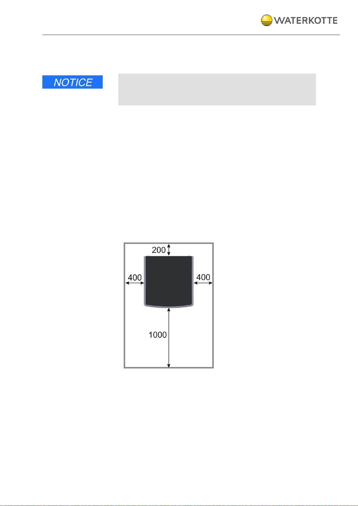
Recommendation:
Wall clearance left, right and on top must be at least 400 mm.
Wall clearance in rear must be at least 200 mm.
Wall clearance in front: at least 1.000 mm.
Figure 3: Recommendation - Installation distance from the wall
Installation and connection
05.06.2015
18 / 80
Copyright 2013 by: WATERKOTTE GmbH. Subject to changes.
6.2 Environmental conditions for installation
Note the minimum volume of the installation room and consider the type of
the refrigerant (EN 378-1).
The room must be dry. Room temperature should be between +5 °C and
+25 °C. To facilitate maintenance, the use of a base plate is recommended.
To compensate for minor unevenness, we recommend use of an approx.
10 mm thick rubber mat.
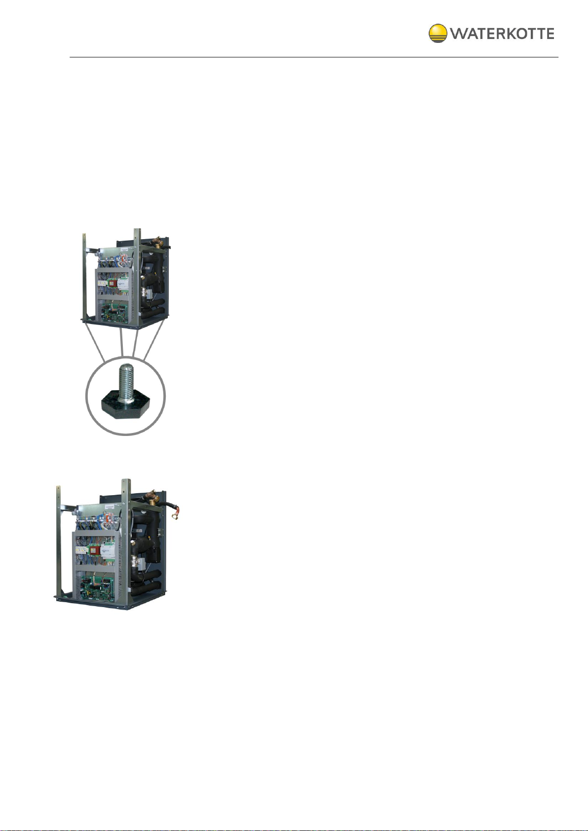
6.2.1 Installation of the heat pump
Transport the EcoTouch Ai1Air to installation site. Align the heat pump unit
in a horizontal position.
To do this, use the set screws for height adjustment (under the corners of
the unit), width across flats 30 mm.
6.2.2 Preparation of the assembly
After completion of assembly the supply lines have to be accessible.
Arrange them as follows:
Place the connecting tubes of the tank at the side of the unit (right).
Figure 4
: Arrangement of connecting tubes before installation
Installation and connection
05.06.2015
19 / 80
Copyright 2013 by: WATERKOTTE GmbH. Subject to changes.
1
1
1
1
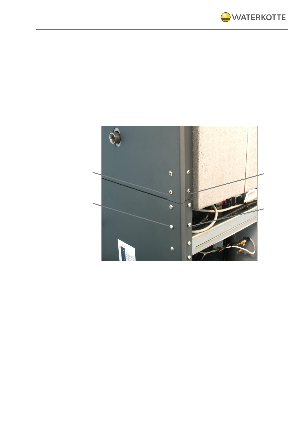
6.2.3 Assembly of the heat pump
Put the domestic hot water tank on the heat pump module in a way that
steel profiles engage with each other and aligned the rear walls clean.
Retain the construction at every steel profile and on the rear wall with the
enclosed 16-lowing screws (fillister head), (M8 self-locking, Z18595).
Tip: To simplify installation, first install the screws on the rear panel.
Note: To mount the tank module two people are needed. The tank module
weighs at least 65 kg.
Figure 5: Rear panel retained with screws (Pos. 1)
Installation and connection
05.06.2015
20 / 80
Copyright 2013 by: WATERKOTTE GmbH. Subject to changes.
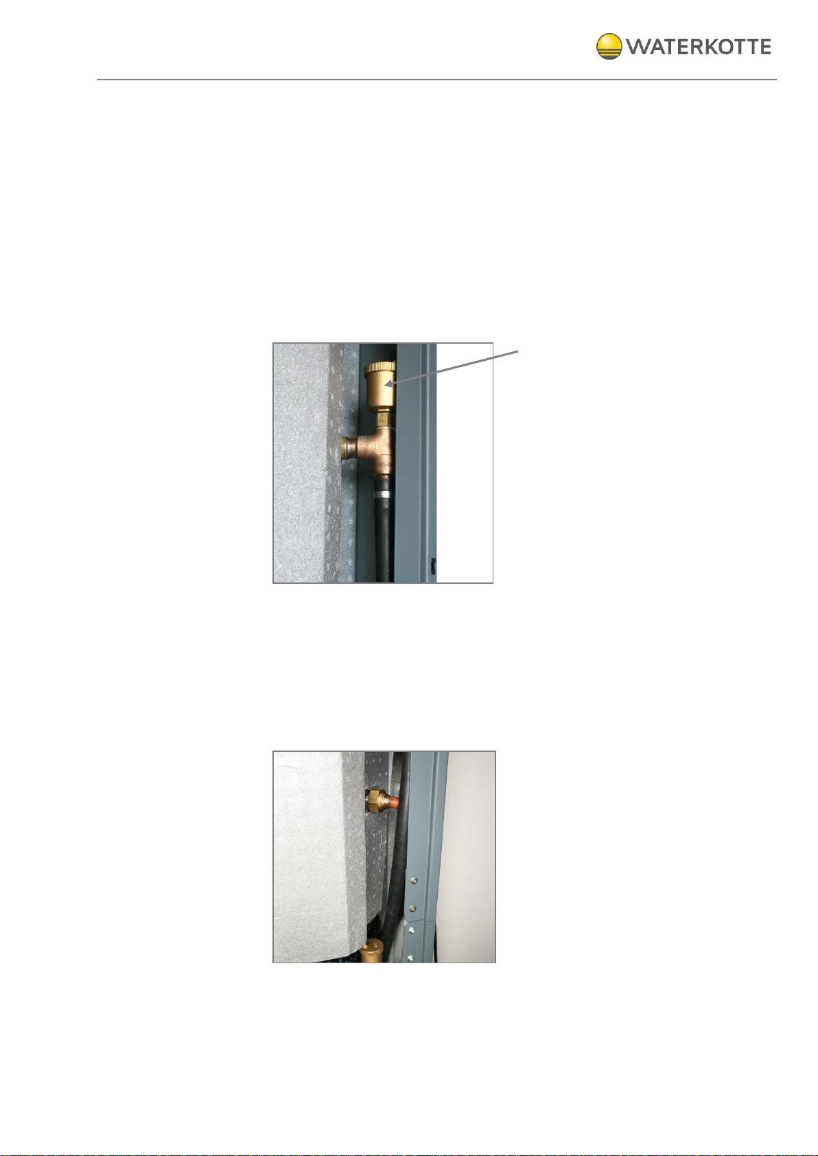
6.2.4 Connection tube of the tank (at the top)
The upper tube connection can not be directed through the insulation with
an installed bleeder. Therefore, the upper part of the bleeder has to be
mounted finally.
Procedure:
Remove the yellow plug.
Install the tube connection at the hot water tank.
Then fit the top of the bleeder (Z13683) on the tee of the connection
tube (see pointing arrow)
Use the supplied gasket.
Figure 6: Connection tube (at the top) with bleeder
6.2.5 Connection tube of the tank (bottom)
The lower connection tube has no bleeder. Remove the yellow plug and
mount the tube connection at the hot water tank. Use the supplied gaskets.
Figure 7: Lower connection tube
Installation and connection
05.06.2015
21 / 80
Copyright 2013 by: WATERKOTTE GmbH. Subject to changes.
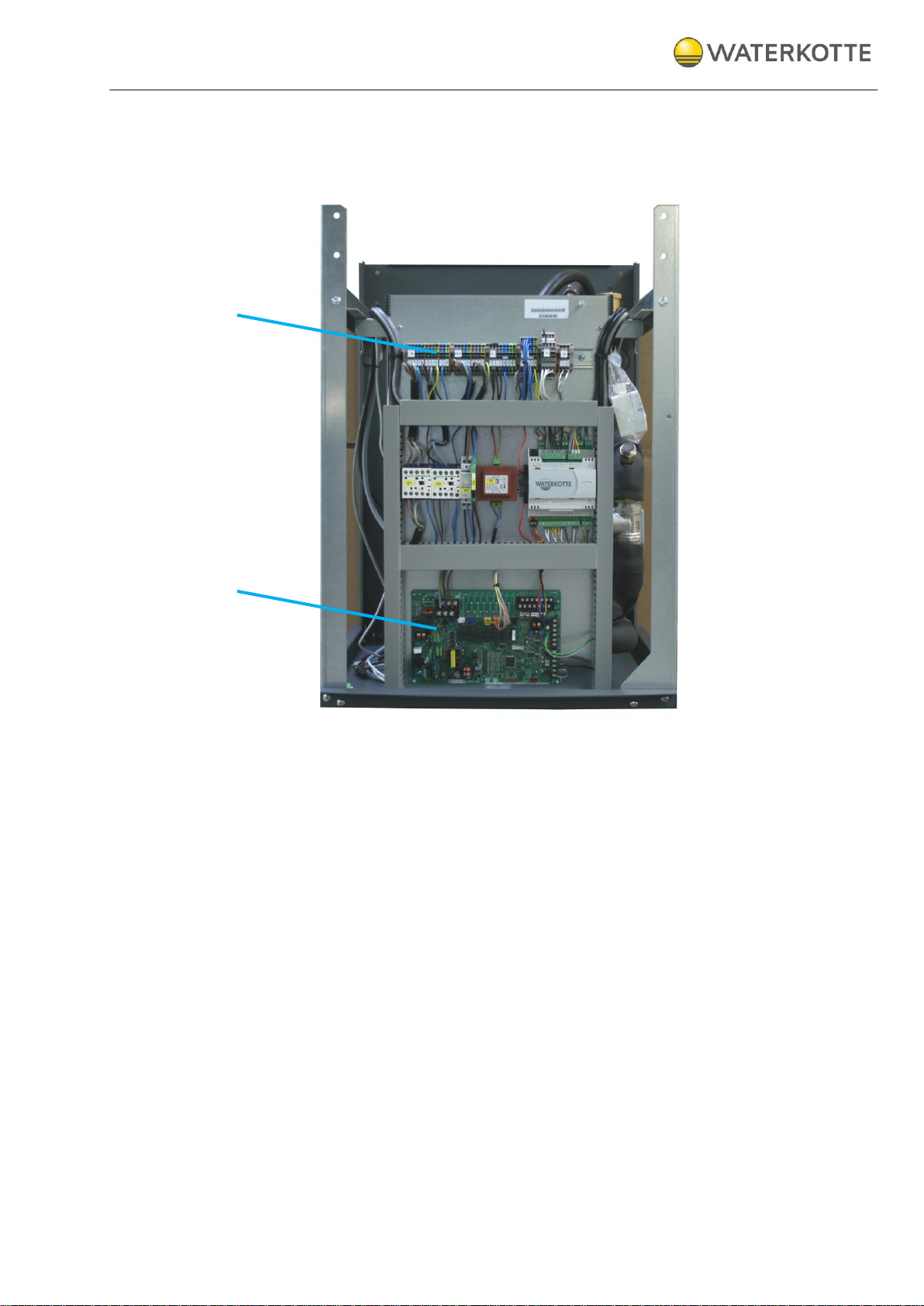
1
2
6.2.6 Connection terminal
The terminals are installed at the front of the heat pump. The clamps (1) and
the mainboard (2) are to find here, too.
Figure 8: Connection terminal EcoTouch Ai1 Air
Installation and connection
05.06.2015
22 / 80
Copyright 2013 by: WATERKOTTE GmbH. Subject to changes.
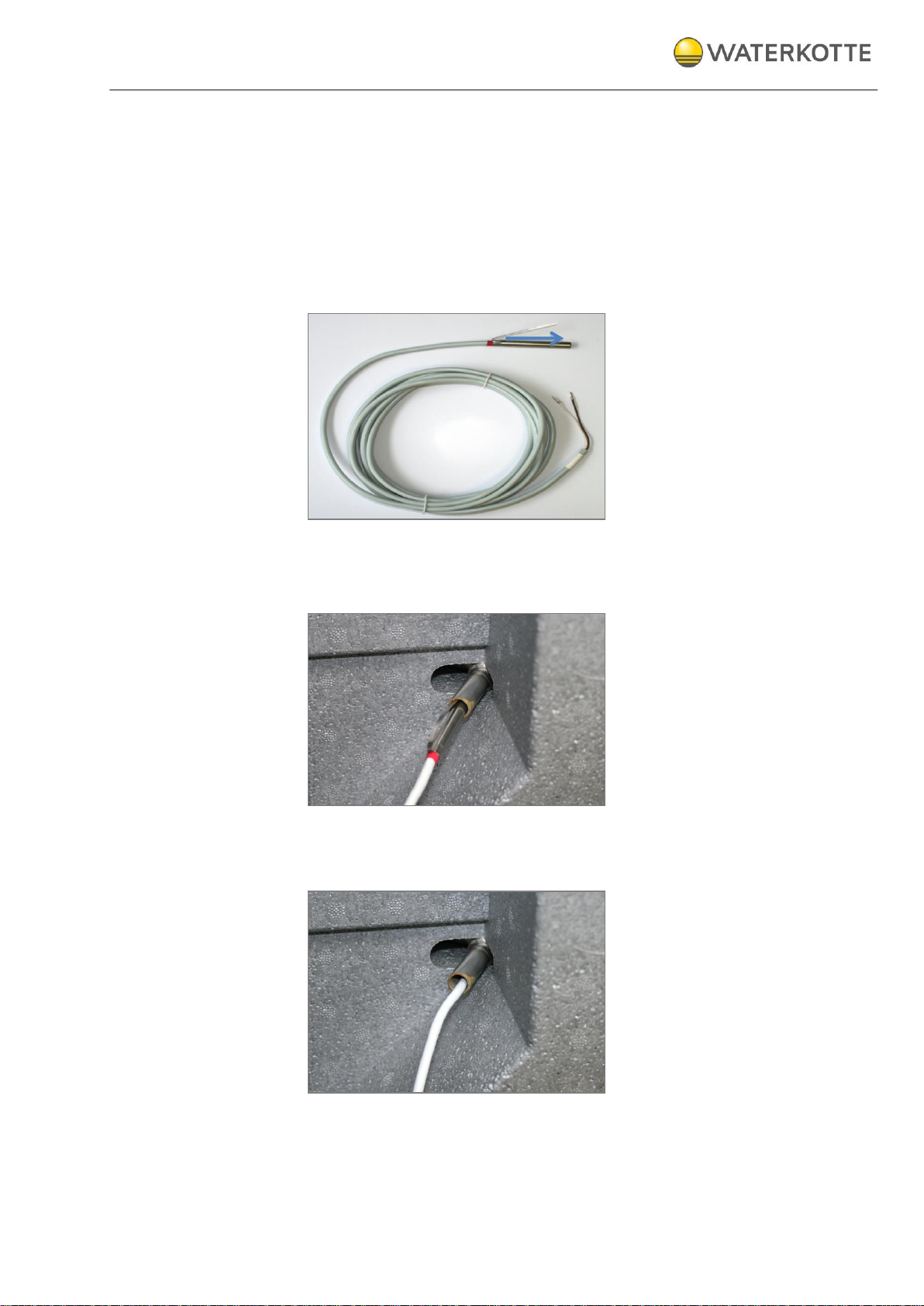
6.2.7 Installation of the temperature sensor
The temperature sensor has a clamping strap to secure positioning in the
immersion sleeve. Before installing bend the clamping strap in the correct
position (see Figure 9). Then push the temperature sensor into the clamping
strap of the hot water tank to the end position.
Connect the temperature sensor to the connection terminal
(Terminal configuration see chap. 10.3).
Figure 9: Temperature sensor with clamping strap (see pointing arrow)
Figure 10: Clamping strap with temperature sensor of the hot water tank
Figure 11: Temperature sensor at the end position
Installation and connection
05.06.2015
23 / 80
Copyright 2013 by: WATERKOTTE GmbH. Subject to changes.
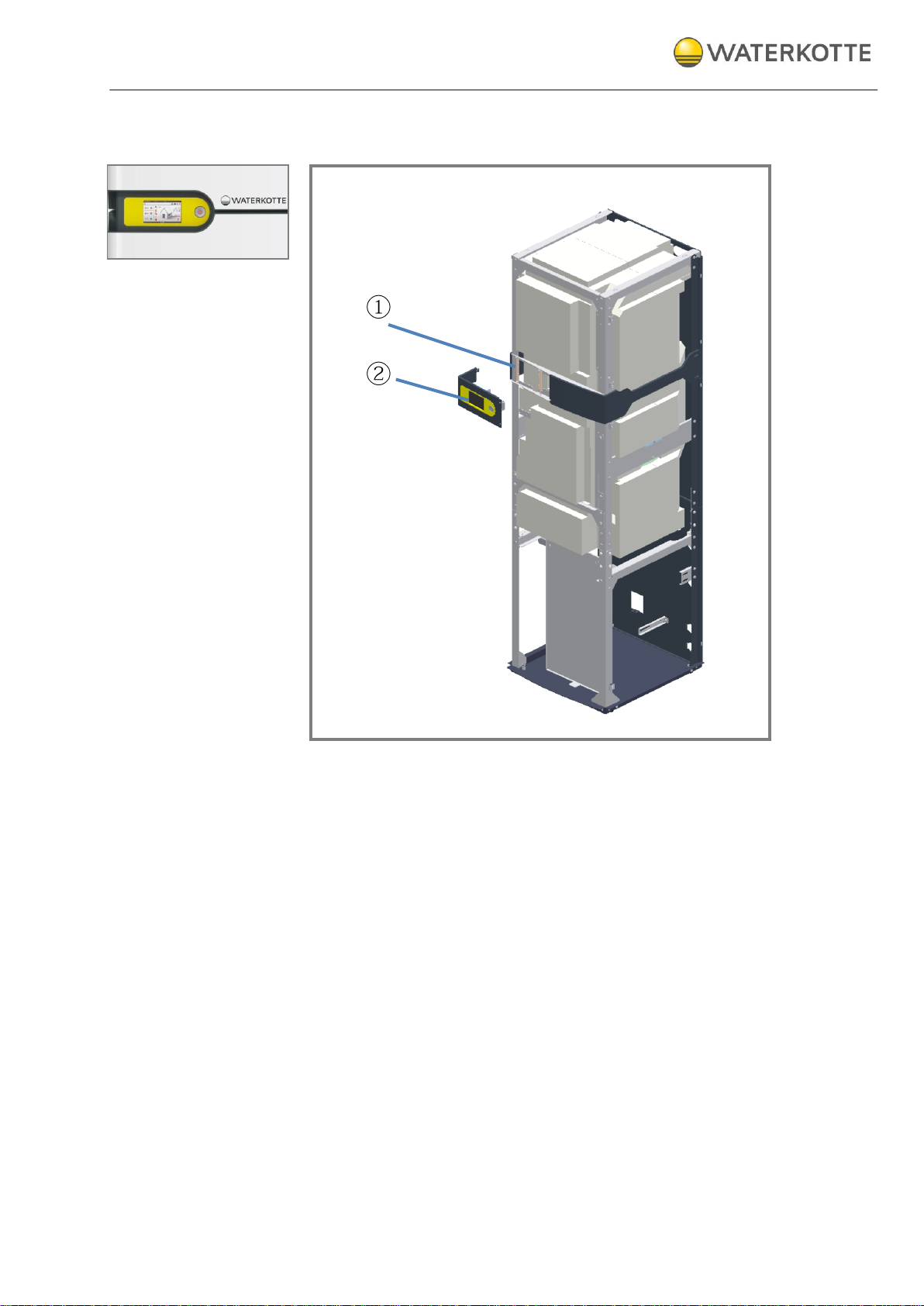
6.2.8 Installation of the Touch Display
Figure 12: Installation of the Touch Display
The touch panel (2) is attached before installing the housing parts.
Procedure:
Plug the connector of the prefabricated cable into the sockets on
the back of the touch panel. Connect the power switch to the cord.
Attach the cable to the left steel profile (cable ties are included).
Slide the tabs of the touch panel in the recordings (1) of the heat
pump frame (on the left).
Fix the frame of the touch panel with two screws.
Installation and connection
05.06.2015
24 / 80
Copyright 2013 by: WATERKOTTE GmbH. Subject to changes.
2
3
6
7
1 5 4
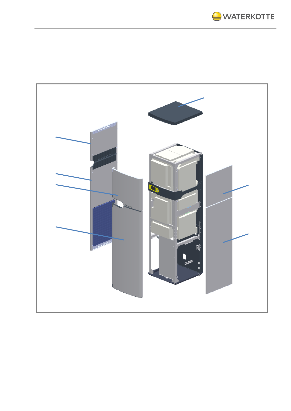
6.2.9 Installation of the housing
To avoid damage, the delivered housing parts are not installed.
After preparation of all connections, mount the housing parts to the intended positions (insert and press). Note the order of assembly (see illustration).
Figure 13: Order of assembly of the housing parts
 Loading...