

WATERKOTTE Basic Line Ail Air Planning And Installation Manual
WATERKOTTE GmbH, Gewerkenstraße 15, D-44628 Herne
Tel.: 0049/(0)2323/9376-0, Fax: 0049/(0)2323/9376-99, E-Mail: info@waterkotte.de
Internet: http://www.waterkotte.de
21.10.2015 / Z21437
Basic Line Ai1 Air – Indoor unit
Basic Line BS7010 – Hydraulikstation
- Indoor unit
Basic Line Ai1 Air /Basic Line BS 7010
- Outdoor unit
Basic Line Ai1 Air /Basic Line BS 7006
- Outdoor unit
Planning and installation
Basic Line Ai1 Air
Air to water heat pump
21.10.2015
2 / 60
Copyright 2014 by: WATERKOTTE GmbH. Subject to changes.
Copyright 2014 by
WATERKOTTE GmbH
Gewerkenstraße 15, 44628 Herne, Germany
All rights reserved. Reproduction, duplication as well as translation of this
publication, or excerpts therefrom, require prior written approval by
WATERKOTTE GmbH.
Illustrations and diagrams serve as explanatory description and shall not be
used as drawings for construction, offers or installation.
All specifications comply with the state of technology at time of printing; we
reserve the right to make changes that serve technical progress.
This publication has been prepared with all reasonable care.
WATERKOTTE GmbH does not assume any liability for remaining errors or
omissions, or for possible damages.
Note: This symbol applies only to countries within the European Union (EU).
This symbol is in compliance with Directive 2002/96/EC, Article 10. The
product has been designed and manufactured with high-quality materials
and components which are suitable for recycling.
This symbol means that electrical and electronic equipment, at the end of
its useful life, shall be disposed of separately from household waste. Please
dispose of this equipment at your designated collection point or local recycling centre.
In the European Union, different collection systems are available for used
electrical and electronic equipment. Please help us conserve the environment we live in!
Never vent R410A into the atmosphere:
R410A is a fluorinated greenhouse gas according to Kyoto Protocol and
has a global warming potential (GWP) of 1975.

21.10.2015
3 / 60
Copyright 2014 by: WATERKOTTE GmbH. Subject to changes.
Content
1 Safety ..................................................................................................................................... 5
1.1 Intended use ...................................................................................................................... 5
1.2 Basic safety precautions .................................................................................................... 5
1.2.1 Keep information available .................................................................................... 5
1.2.2 Before initial use .................................................................................................... 5
1.2.3 Environmental protection ...................................................................................... 6
1.2.4 Modifications and repairs on the heat pump ......................................................... 6
1.3 Hazards ............................................................................................................................. 6
1.4 Operator's duty of care ...................................................................................................... 8
1.5 Other applicable documents .............................................................................................. 8
2 Product description and scope of delivery ................................................................................ 9
2.1 Overview............................................................................................................................ 9
2.1.1 Basic Line Ai1 Air /BS 7010 (outdoor module) .................................................... 10
2.1.2 Basic Line Ai1 Air (indoor module) ....................................................................... 10
2.1.3 Basic Line BS Hyd 5010 hydraulic station ........................................................... 10
3 Components and installation .................................................................................................. 11
3.1 Heating system Basic Line Ai1 Air BS 7010 / BS 7006 .................................................... 11
3.2 Structure and control ....................................................................................................... 11
3.2.1 Electronic heat pump control .............................................................................. 11
4 Transport to installation site ................................................................................................... 12
4.1 Environmental conditions for installation (indoor module) ................................................. 12
4.2 Residual head circulation pump (heating) ......................................................................... 12
5 Installation and connection .................................................................................................... 13
5.1 Installation and connection of indoor unit ......................................................................... 13
5.2 Environmental conditions for installation .......................................................................... 13
5.3 Dimensions and connections outdoor module BS 7010 (5010.5) .................................... 14
5.4 Dimensions and connections outdoor module BS 7006 (5006.5) .................................... 15
5.5 Dimensions and connections (indoor module) Basic Line Ai1 Air ..................................... 16
5.6 Dimensions and connections (indoor module) BS Hyd 5010 hydraulic station ................. 17
5.7 Installation of cover and cladding panels .......................................................................... 18
5.8 Disassembly of cladding panels ....................................................................................... 18
5.9 Disassembly of cover and cladding panels (outdoor module) ........................................... 18
6 Installation and connection of the outdoor module .................................................................. 19
6.1 Selecting a location for outdoor module .......................................................................... 19
6.2 Clearance for ventilation and operation ............................................................................ 20
6.3 Installation in base plate or on the wall ............................................................................. 20
6.4 Installation and space requirement .................................................................................. 21
7 Connection lines ................................................................................................................... 22
7.1 Refrigerant charge and additional charge ........................................................................ 22
7.2 Oil traps ........................................................................................................................... 23
7.3 Insulation ......................................................................................................................... 23
7.3.1 Tube airtight testing method (recommended procedure), test equipment nitrogen24
7.4 Connection outdoor module / indoor module (refrigerant lines) Basic Line Ai1 Air ............ 25
7.5 Connections (refrigerant and heating) indoor module hydraulic station ............................. 26

21.10.2015
4 / 60
Copyright 2014 by: WATERKOTTE GmbH. Subject to changes.
7.6 Connections outdoor module (refrigerant line) .................................................................. 27
8 Refrigerant ............................................................................................................................ 28
8.1 Requirements on handling of R410A refrigerant ............................................................... 28
8.2 Safety guidelines for the handling of refrigerants .............................................................. 28
8.3 Charging refrigerant circuit ............................................................................................... 29
8.4 Mounting (heating /domestic water side) ......................................................................... 30
9 Electrical work ....................................................................................................................... 31
9.1 Electrical connection outdoor module .............................................................................. 32
9.1.1 Cable cross sections/types ................................................................................. 32
9.2 Electrical connection (indoor module) (hydraulic station / control module) ........................ 32
9.2.1 Installing external wall sensor .............................................................................. 32
9.2.2 Power supply- Heating element.......................................................................... 32
9.2.3 Heating element - thermostat setting .................................................................. 32
9.3 Electrical and BUS connection (outdoor module BS 7010.5) ........................................... 33
9.4 Electrical and BUS connection (outdoor module, BS 7006.5) .......................................... 34
9.5 Electrical connection Basic Line Ai1 Air (5010.5) (indoor module)..................................... 35
9.6 Electrical and BUS connection Basic Line BS Hyd 5010 hydraulic station ....................... 35
9.6.1 DIP-Switch (outdoor module) .............................................................................. 35
9.7 Electrical wiring diagram Basic Line Ai1 Air / BS 7010 (outdoor module) ......................... 36
9.8 Electrical wiring diagram - Basic Line Ai1 Air (indoor module) .......................................... 37
9.9 Electrical wiring diagram - Basic Line BS Hyd 5010 hydraulic station (indoor module) ..... 38
9.10 WWPR2 Controler - connections ..................................................................................... 39
9.11 Electrical connections ...................................................................................................... 40
10 Commissioning ..................................................................................................................... 41
10.1 Pre-startup checks .......................................................................................................... 41
10.2 Initial start of heat pump .................................................................................................. 43
10.3 Control of entire operation ............................................................................................... 44
10.4 Turning heat pump off ..................................................................................................... 44
10.5 Taking heat pump out of operation for extended period .................................................. 44
11 Technical data ...................................................................................................................... 45
12 Connection diagram .............................................................................................................. 46
12.1 Basic Line Ai1 Air with underfloor heating, without single room control ............................ 46
12.2 Basic Line Ai1 Air with underfloor heating, with single room control ................................ 47
12.3 Basic Line Ai1 Air with radiators / fan convectors ........................................................... 48
12.4 Basic Line Ai1 Air with hydraulic compensator ................................................................ 49
12.5 Basic Line Ai1 Air hydraulic compensator and additional heater ...................................... 50
12.6 Basic Line BS 7010 with underfloor heating, without single room control ........................ 51
12.7 Basic Line BS 7010 with underfloor heating, without single room control, decentral domestic
hot water preparation ................................................................................................................. 52
12.8 Legend (hydraulic schemes) ............................................................................................ 53
13 Refrigeration circuit Basic Line Ai1 Air / BS 7010 .................................................................... 55
14 Maintenance and inspection .................................................................................................. 57

Safety
21.10.2015
5 / 60
Copyright 2014 by: WATERKOTTE GmbH. Subject to changes.
1 Safety
1.1 Intended use
Your WATERKOTTE heat pump of the Basic Line series is used for space
heating and cooling, and heating of domestic water.
An outdoor module, which is coupled to a heat source (air) that is available
year-round, serves as heat generator.
Project planning of the heat source system must be performed in compliance with the technical information provided by WATERKOTTE for layout of
heat source systems. Heat pump shall only be turned on after the refrigerant connections are completely charged, and the other hydraulic circuits
are completely charged and vented, and all electrical connections are
properly completed.
Commissioning may only be carried out by trained professionals. Damages
caused by non-compliance with above mentioned items are not covered by
the warranty (see enclosed Exclusion of Warranty).
1.2 Basic safety precautions
1.2.1 Keep information available
In addition to the operating manual, also furnish operating instructions in
terms of Labour Protection Law and Work Equipment ordinance. Keep all
safety and operating signs on the heat pump in fully legible condition at all
times. Replace damaged or illegible signs immediately.
1.2.2 Before initial use
Before initial use of your WATERKOTTE heat pump, familiarise yourself with:
Operating and control elements of your WATERKOTTE heat pump
Equipment of heat pump
Operation of heat pump
Immediate surroundings of heat pump
Safety devices of heat pump
Before initial start, perform the following steps:
Ensure that all safety devices are installed and function as intended.
Check heat pump for visible damage. Eliminate any detected defects
immediately. Heat pump may only be operated in perfect condition!
Ensure that only authorised personnel is in the work area of the heat
pump and that no other persons are endangered when heat pump is
started.
Remove all objects and other materials that are not required for opera-
tion of the heat pump from the work area of the heat pump.
Activate the electrical connection; the module must be in standby mode
(oil sump heater active).
Check heating circuit temperature: Temperature heating circuit below
16 °C.
Safety
21.10.2015
6 / 60
Copyright 2014 by: WATERKOTTE GmbH. Subject to changes.
1.2.3 Environmental protection
Observe the regulations regarding waste avoidance and proper waste
recycling or disposal when performing any kind of work on and with the
heat pump.
Ensure that particularly during installation and maintenance work, as well
as when placing out of operation, groundwater pollutants such as
grease, oils, refrigerants, solvent-containing cleaning fluids, etc. do not
contaminate the ground or enter into the sewer system!
These substances must be collected, stored, transported, and disposed
of in suitable containers.
1.2.4 Modifications and repairs on the heat pump
For safety reasons, no unauthorised modifications shall be performed on
the heat pump.
Thus, all intended modifications are subject to written approval by
WATERKOTTE.
Use only original WATERKOTTE spare parts.
Original parts are specifically designed for your heat pump. Externally procured parts provide no guarantee that they are designed and manufactured
in compliance with relevant usage and safety requirements.
1.3 Hazards
Parts and special equipment not delivered by WATERKOTTE are not approved for use on the heat pump.
Observe the following points to avoid life-threatening injuries and damages
to the heat pump during operation:
Risk of death by electric shock!
Do not use water or other liquids to clean the system!
Keep all electrical supply modules locked at all times!
Any work on the electrical equipment of the heat pump shall only be performed by professional electricians!
Safety
21.10.2015
7 / 60
Copyright 2014 by: WATERKOTTE GmbH. Subject to changes.
Leaking refrigerant can result in severe personal injuries (suffocation or hypothermia)!
Avoid direct contact with refrigerant!
When selecting the installation site, observe the minimum volume under
consideration of the refrigerant applied (as per EN 378-1).
Risk of burns!
During operation, surface temperatures (compressor and pressure line) can
climb above 100 °C or drop below 0 °C.
Do not remove housing cover during operation!
Allow heat pump to cool down before removing cover.
Risk of injury!
Risk of chemical burns when skin comes in direct contact with lubricant
leak.
Wear suitable clothing when performing maintenance work on the heat
pump!
Do not put your fingers or others into the fan, or evaporator.
The inside parts of the heat pump may run at high speed or high temperature, they could cause serious injury. Do not remove the grills on the fan
outlet and top cover.
The hot water probable need to mix with cold water for terminal usage, too
hot water (over 50 °C in the heating module may cause injury.
The installation height of power supply should be over 1.8m, if any water
may spatter, the module can be safe from water.
Electrostatic charge!
Electronic components can be damaged by electrostatic processes.
Ground yourself before touching electronic components.
Risk of total loss!
Repeated restart of the heat pump can result in total loss! In case of heat
pump failure, an inspection by qualified and authorised personnel must be
performed before restart.

Safety
21.10.2015
8 / 60
Copyright 2014 by: WATERKOTTE GmbH. Subject to changes.
1.4 Operator's duty of care
Your WATERKOTTE heat pump has been designed and built on the basis
of a risk analysis and after careful selection of standards to be observed.
Thus, your heat pump is state-of-the-art and provides for maximum safety.
In practice, however, this safety can only be ensured by taking all necessary
measures. As operator of the heat pump it is your responsibility to plan
these measures and oversee their implementation.
You must ensure that:
The heat pump is only used as intended (see also chapter 1.1,
The heat pump is only operated in perfect, fully functional condition and
The operating manual is available in perfect condition at the heat pump
The heat pump is operated, maintained and repaired only by adequately
None of the safety and warning notices on the heat pump are removed
"Intended use").
safety devices are checked regularly to ensure that they are working
properly.
at all times.
qualified and authorised personnel.
or damaged.
1.5 Other applicable documents
Operating manual: WATERKOTTE heat pump controller.
WATERKOTTE technical information

Product description and scope of delivery
21.10.2015
9 / 60
Copyright 2014 by: WATERKOTTE GmbH. Subject to changes.
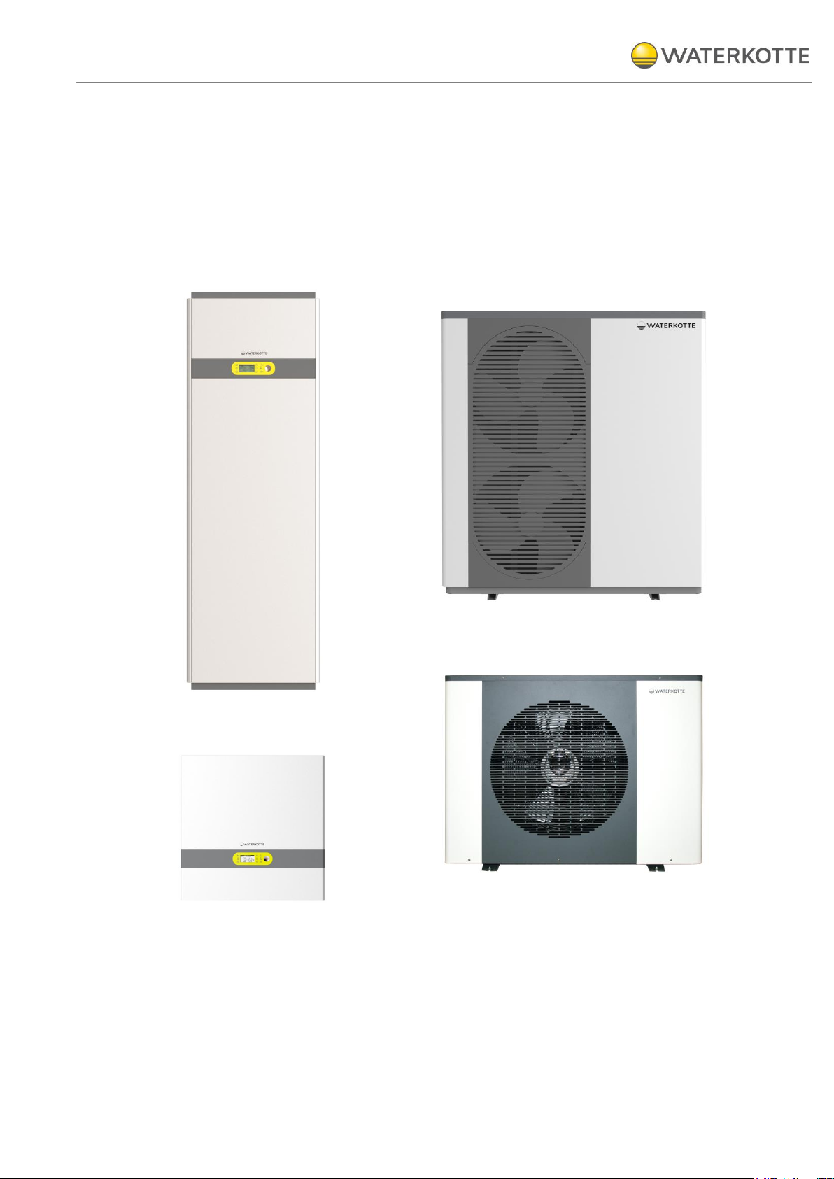
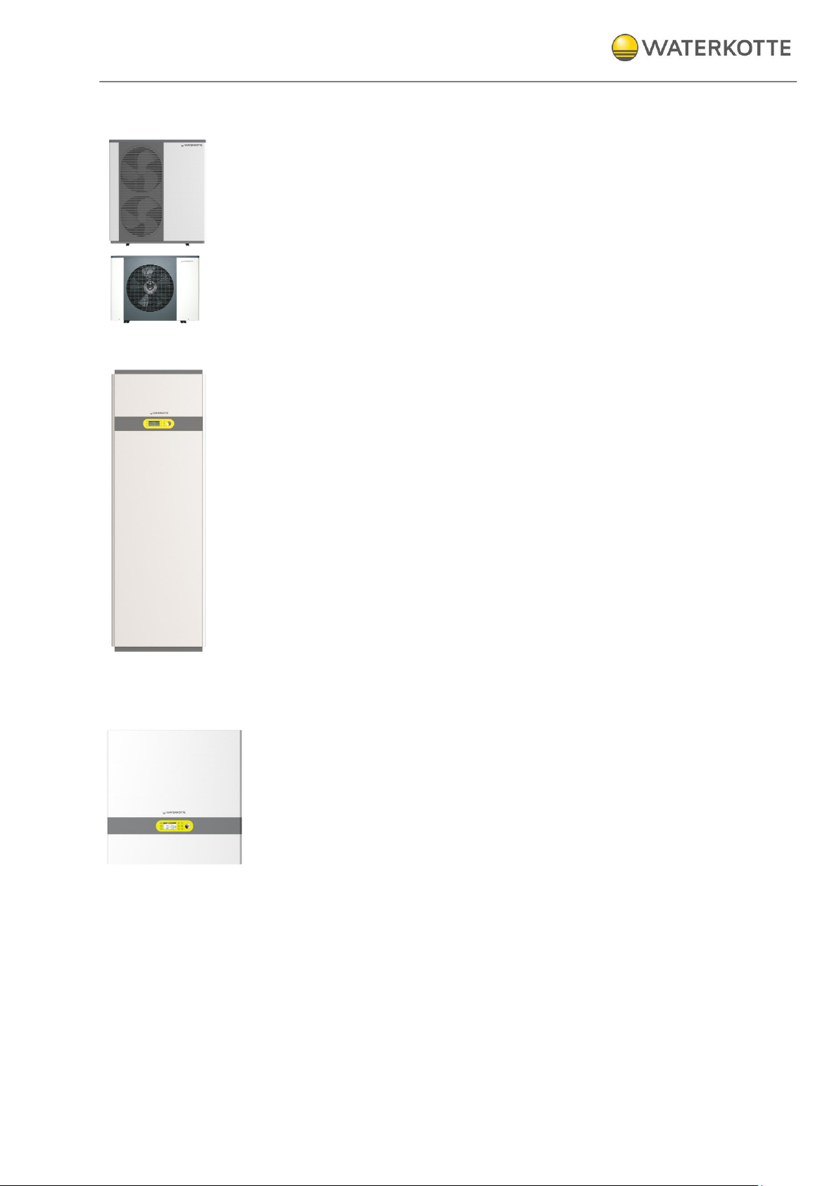
1
Basic Line Ai1 Air /BS 7010 - (outdoor module)
2
Basic Line Ai1 Air /BS 7006 - (outdoor module)
3
Basic Line Ai1 Air - (indoor module)
4
Basic Line BS Hyd 5010 hydraulic station – (indoor
module)
4
3
1
2
2 Product description and scope of delivery
2.1 Overview
Product description and scope of delivery
21.10.2015
10 / 60
Copyright 2014 by: WATERKOTTE GmbH. Subject to changes.
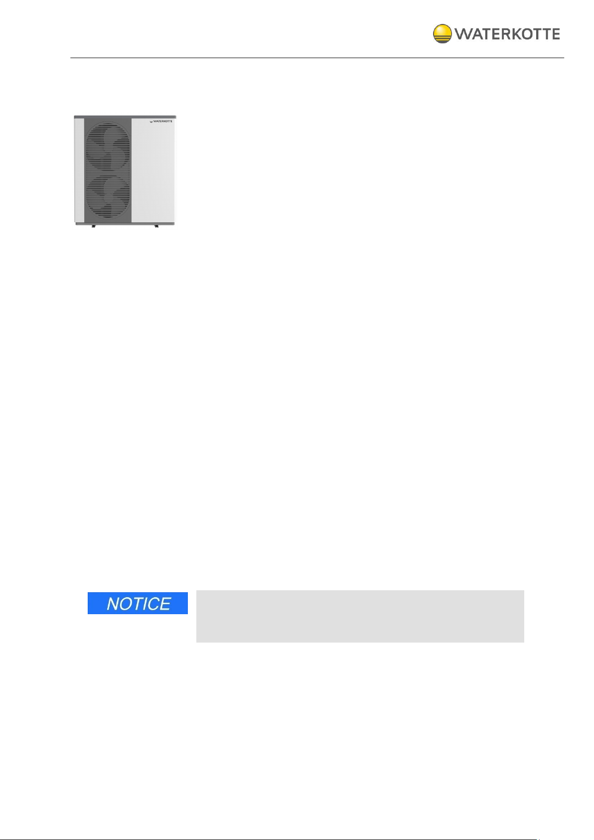
2.1.1 Basic Line Ai1 Air /BS 7010 (outdoor module)
The device contains:
Compressor, inverter controlled
Evaporator
Fans
Inverter board, EVD
2.1.2 Basic Line Ai1 Air (indoor module)
The indoor module contains:
Integrated hot water tank 170 l
Monochrome, semi-graphic, 8-line display
Central power switch
6 convenient buttons and 3 indicator LEDs
Intuitive control software BasicPro
Speed-controlled circulation pump, efficiency class A
Integrated electrical heating element 6 kW
Combination fitting with safety valve
Air vent
3-way motor ball valve
membrane expansion tank
2.1.3 Basic Line BS Hyd 5010 hydraulic station
The hydraulik station contains:
Monochrome, semi-graphic, 8-line display
Central power switch
Outdoor temperature sensor
6 convenient buttons and 3 indicator LEDs
Intuitive control software BasicPro
Speed-controlled circulation pump, efficiency class A
Integrated electrical heating element 6 kW
Combination fitting with safety valve
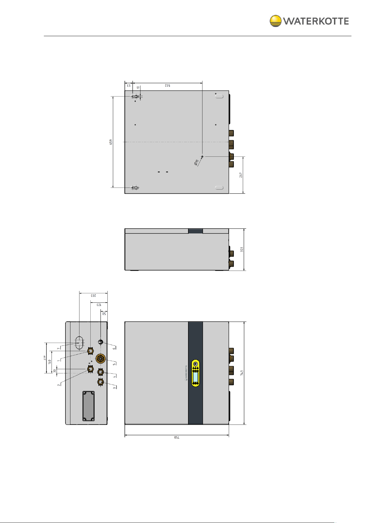
Metal housing (W x H x D) 743 x 750 x 303 mm
Docking features for 1 additional module: e.g. domestic hot water tank,
living area ventilation
Series options
Hydraulic station incl. control (only heating)
- Art. Nr.: BS701059CH
Hydraulic station incl. control (heating and domestic hot water)
- Art. Nr.: BS701059CHW
Components and installation
21.10.2015
11 / 60
Copyright 2014 by: WATERKOTTE GmbH. Subject to changes.
3 Components and installation
3.1 Heating system Basic Line Ai1 Air BS 7010 / BS 7006
The newly developed heating system was designed as a compact air
source heat pump for outdoor installation. It is suitable for heating and
cooling low-energy buildings.
Thanks to the inverter-controlled compressor, the Basic Line Ai1 Air and BS
7010 operate extremely energy-efficiently. Due to the infinitely variable
adjustment of the power it impresses with high performance. Even at
outdoor temperatures of -15 °C, flow temperatures of 55° C are possible
The outdoor module contains all the heat pump technology (nicht der not
the condenser). The control moduel with the tank (Ai1 Air) or the hydraulic
module BS Hyd 5010 are installed in the building.
3.2 Structure and control
Complete hot water heating system with integrated central hot water supply
(option), consisting of: heat generator (heat pump), regulation and electrical
control, complete electrics and control system, semi-graphic display.
3.2.1 Electronic heat pump control
The heat pump control is included in the delivery scope of the
WATERKOTTE heat pump. Use in other than
WATERKOTTE heat pumps will void any warranty claim.
Info: Technical details, operation and warning messages (see
manual for heat pump control
The control is used to control and monitor heating systems that are operated with WATERKOTTE compact heat pumps according to technical guidelines of WATERKOTTE Wärmepumpen GmbH. All tasks to do with control
are fulfilled (depending on the external temperature, control, monitoring,
self-diagnosis, saving of data in case of breakdown, etc.
WATERKOTTE explicitly states that function warranty will become void if
used on systems not approved by WATERKOTTE. Any liability for consequential damages due to incorrect function within these systems shall be
explicitly excluded.
Operating
).
Transport to installation site
21.10.2015
12 / 60
Copyright 2014 by: WATERKOTTE GmbH. Subject to changes.
Residual head circulation pump (heating)
- Hydraulic station BS Hyd 5010
- Indoor module Basic Line Ai1 Air
10 kW ∆t=5K
6 m
4 Transport to installation site
Modules of the Basic Line 7010 series are delivered ready-to-connect with
metal cladding. The Basic Line Ai1 Air / Basic Line 7010 are delivered ready
for connection.
Since the heat pump module weighs 120 kg or more, for instance, at least
two people are required for transport.
The devices are mounted on top of each other only at the installation site.
During transport it must be ensured that appropriate means of transport are
used (lift truck, transport rollers, handcart).
It is crucial that the heat pump is transported upright!
Transport in tilted position (45°) is permitted only temporarily during insertion. Horizontal transport results in oil displacement in compressor and can
cause damage to the heat pump during start-up.
After carton is removed or opened it is not permitted to tilt the module by
applying pressure to the pipelines or housing enclosure; this could result in
bent housing parts and pipelines.
4.1 Environmental conditions for installation (indoor module)
The room must be dry. Room temperature should be between +5 °C and
+25 °C.
4.2 Residual head circulation pump (heating)

Installation and connection
21.10.2015
13 / 60
Copyright 2014 by: WATERKOTTE GmbH. Subject to changes.
5 Installation and connection
5.1 Installation and connection of indoor unit
To make hydraulic connections, you must use the supplied material (connecting lines and gaskets).
During assembly of connecting lines, use an according tool as brace to
prevent damage to the heat distribution station.
Installation of the indoor unit must be performed on a flat and horizontal
surface.
Wall clearance (free space) in front: at least 1000 mm.
Due to the connections on the rear of the unit, the mounting distance to
the wall (rear, right side, left side) must be selected in such a way that
access is ensured in case of repairs.
Recommendation for good service accessibility: Wall clearance (free
space), left, right 400 mm. Wall clearance rear at least
300 mm.
Figure 1: Recommendation - wall clearance for installation
5.2 Environmental conditions for installation
When selecting the installation site, observe the minimum volume under
consideration of the refrigerant applied (as per EN 378-1).
The room must be dry. Room temperature should be between +5 °C and
+25 °C. To facilitate maintenance, the use of a base plate is recommended.
To compensate for minor unevenness, we recommend use of an approx.
10 mm thick rubber mat.

Installation and connection
21.10.2015
14 / 60
Copyright 2014 by: WATERKOTTE GmbH. Subject to changes.
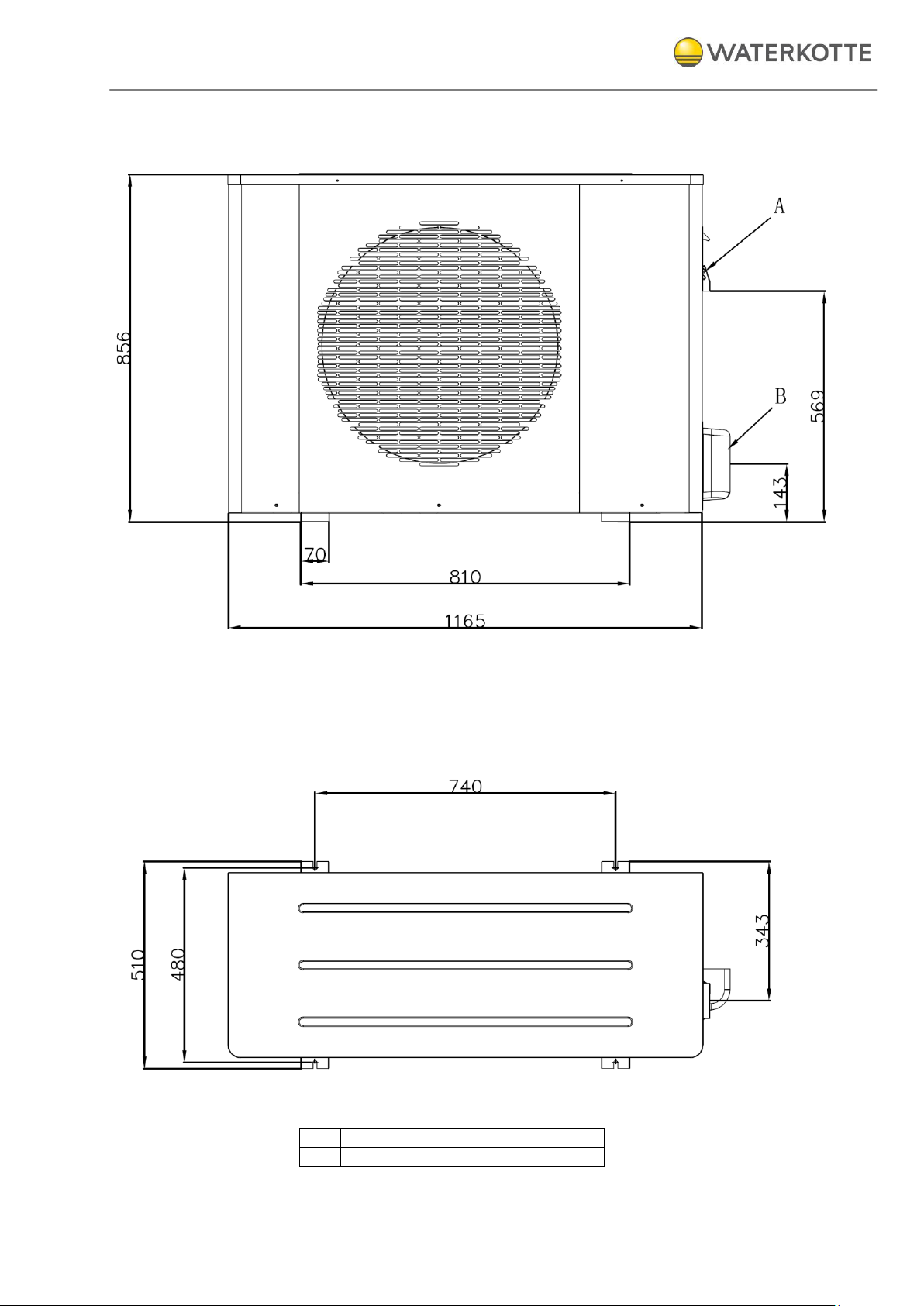
A
Cable entries, electrical connection
B
Cover: connection refrigerant line
A
B
5.3 Dimensions and connections outdoor module BS 7010 (5010.5)
Figure 2: Dimensions outdoor module BS 7010 (all dimensions mm)
Installation and connection
21.10.2015
15 / 60
Copyright 2014 by: WATERKOTTE GmbH. Subject to changes.
A
Cable entries, electrical connection
B
Cover: connection refrigerant line
5.4 Dimensions and connections outdoor module BS 7006 (5006.5)
Figure 3: Dimensions outdoor module BS 7006 (all dimensions mm)
Installation and connection
21.10.2015
16 / 60
Copyright 2014 by: WATERKOTTE GmbH. Subject to changes.
5.5 Dimensions and connections (indoor module) Basic Line Ai1 Air
Figure 4: Dimensions indoor module Basic Line Ai1 Air (all dimensions mm
Installation and connection
21.10.2015
17 / 60
Copyright 2014 by: WATERKOTTE GmbH. Subject to changes.
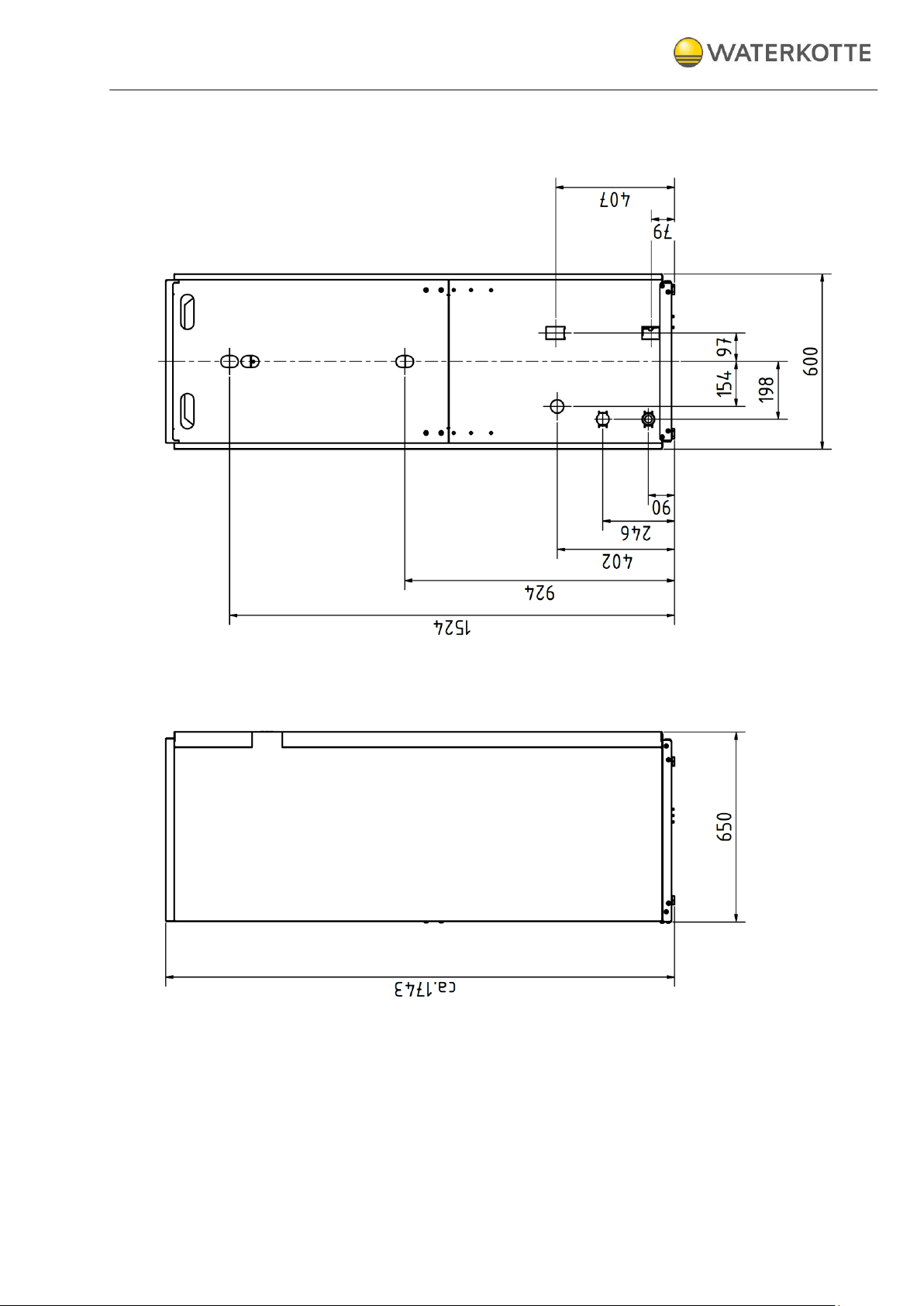
5.6 Dimensions and connections (indoor module) BS Hyd 5010 hydraulic station
Figure 5: Dimensions indoor module (buttom)
Installation and connection
21.10.2015
18 / 60
Copyright 2014 by: WATERKOTTE GmbH. Subject to changes.
5.7 Installation of cover and cladding panels
To prevent transport damage, the cover, front and side panels of the heat
pump are enclosed separately.
After establishing all connections, mount them to the required positions (insert and press).
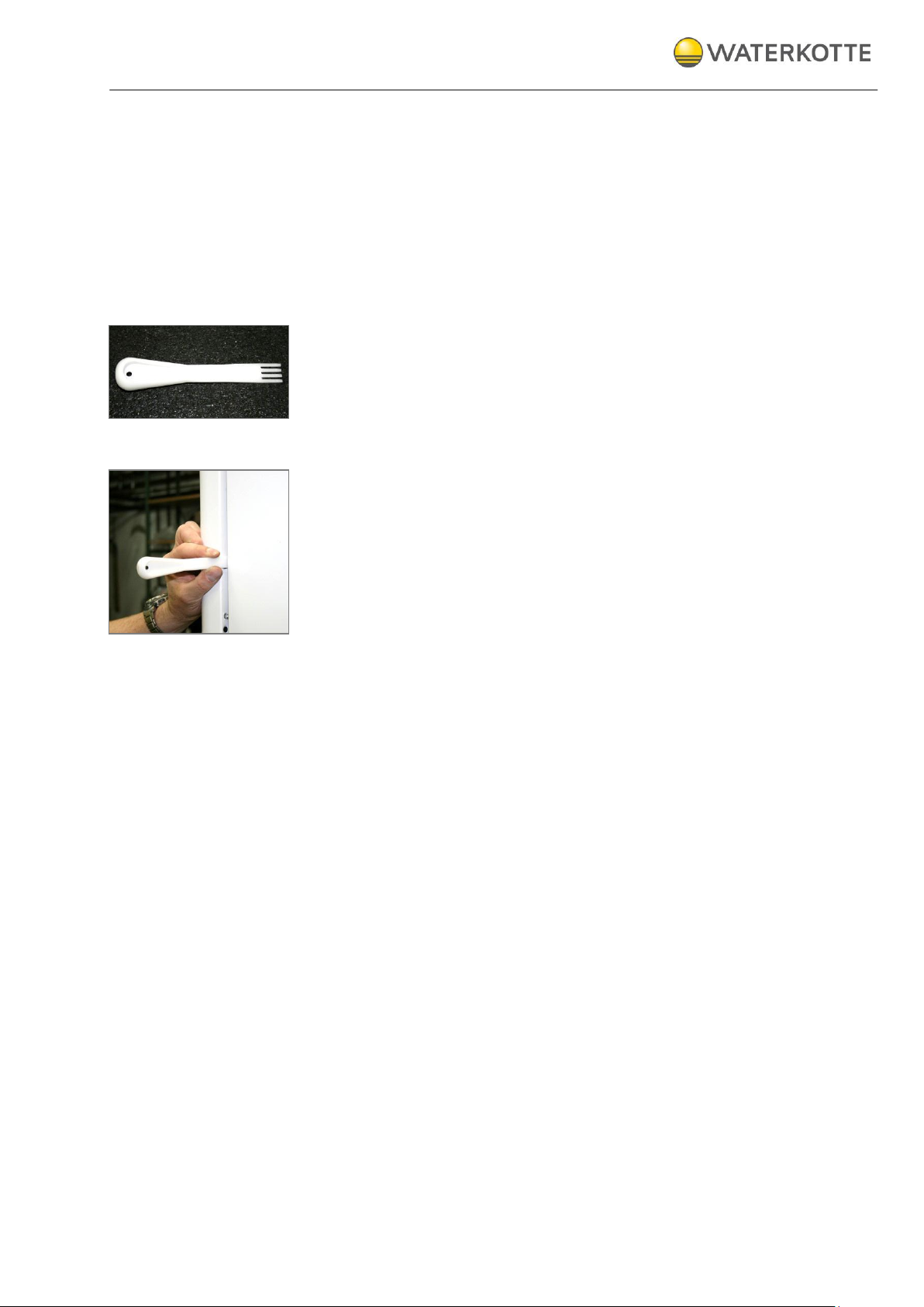
5.8 Disassembly of cladding panels
The heat pump is provided with a disassembly tool. Use this tool to remove
the cladding panels to prevent damage.
Procedure:
Keep enough distance with the disassembly tool to the upper/lower
panel edge so as not to damage the retaining bolt (see figure).
The disassembly tool is manually driven into the gap between the front
and side panel with moderate force.
5.9 Disassembly of cover and cladding panels (outdoor module)
Cover and cladding panels are fixed with screws. In the case of a disassembly the screws must be removed with an appropriate screwdriver.
 Loading...