

Waterite FUSION2 Owner's Manual

Advanced Water Conditioners
featuring the Custom Control F2CC Valve
OWNER’S MANUAL
FOR ALL FUSION² F SERIES AND FCA SERIES WATER CONDITIONERS
THIS MANUAL IS TO BE LEFT WITH THE OWNER OF THE EQUIPMENT FOR
REFERENCE PURPOSES AND TECHNICAL GUIDANCE. IT IS STRONGLY
RECOMMENDED THAT QUALIFIED DEALER SERVICE PERSONNEL BE
CONTACTED IN THE EVENT OF AN UNKNOWN INTERRUPTION OF SERVICE OR
APPARENT PRODUCT MALFUNCTION. AN ANNUAL PREVENTATIVE
MAINTENANCE INSPECTION BY A WATER PROFESSIONAL IS RECOMMENDED
TO ENSURE TROUBLE-FREE AND CONTINUOUS OPERATION.
Waterite Technologies, Inc. ■ 1-885 Keewatin Street, Winnipeg, MB Canada ■ R2X 2S7
www.waterite.com

TABLE OF CONTENTS
Preinstallation Instructions for Dealer.......................inside front cover
Specifications.................................................................................1
Cycle Sequence Settings................................................................2
Softener System Setup (programming)...........................................3-5
Bypass Valve Description & Diagrams..............................................6
Installation...................................................................................7-8
Installer Settings....
Hardness, Override, Regen Time & Time of Day..................
Normal Operating & Error Displays, Power Loss..................10
Low Salt Warning & Resetting It
Start Up Instructions......................................................................12
Replacement Parts & Valve Repair
Front Cover, Drive Assembly and Piston..............................13
Injector Assembly & Refill Port Assembly............................14
Drain Line 3/4" Assembly & Flow Controls
Drain Line 1" Assembly & Flow Controls
Water Meter & Bypass Valve..............................................17
Installation Fitting Assemblies & Service Wrench.................18
Control Valve Servicing..............................................................19-23
Troubleshooting Procedures
.......................................................24-25
.........................................11
..........................15
.............................16
....9
PREINSTALLATION INSTRUCTIONS
This unit has a control valve which enables the setting of not only the length of each regeneration cycle but also the
order in which cycles (steps of regeneration) occur. The following pages instruct how to set the treatment unit’s
sequence of cycles, cycle times, salt dose, exchange capacity, and gallon capacity/regeneration time. A salt
warning option may also be included.
THE DEALER...
1. Read this page, GENERAL INSTRUCTIONS, INSTALLER SETTINGS, NORMAL OPERATING
DISPLAYS, and LOW SALT WARNING.
2. Complete the CYCLE SEQUENCE SETTINGS.
3. Complete the SOFTENER SYSTEM SETUP.
a. Cycle Times
b. Choose Softener or Filter
c. Set Salt Dose
d. Set Capacity
e. Set How Gallon Capacity Will be Calculated
f. Set Regeneration Time Option
g. Select or Turn Off Low Salt Warning
THE INSTALLER...
1. Read Bypass Valve page.
2. Read GENERAL INSTRUCTIONS, NORMAL OPERATING DISPLAYS, and RESETTING LOW SALT
WARNING (if applicable).
3. Be sure CYCLE SEQUENCE SETTINGS and SOFTENER SYSTEM SETUP are done before leaving for
installation.
4. Follow INSTALLATION INSTRUCTIONS, INSTALLER SETTINGS, TIME OF DAY, and RESETTING
SALT AMOUNT (if applicable).
5. Follow START UP INSTRUCTIONS.
page 1

CONTROL VALVE SPECIFICATIONS
SERVICE FLOW RATE & PRESSURE LOSS
27 gpm (102.2 lpm) @ 15 psi (103 kPa)
(valve only, including bypass valve, but not
including mineral, etc.)
BACKWASH FLOW RATE & PRESSURE LOSS
27 gpm (102.2 lpm) @ 25 psi (172 kPa) ∆∆∆∆P
(whole conditioner...including bypass valve)
MINIMUM & MAXIMUM OPERATING
20 psi (138 kPa) - 125 psi ( 862 kPa)
PRESSURE
MINIMUM & MAXIMUM OPERATING
40∞F (4∞C) -110∞F (38∞C)
TEMPERATURE
CURRENT DRAW & VOLTAGE 0.5 amperes 110 volts
REGENERANT TANK REFILL RATE 0.5 gpm (1.9 lpm)
INLET / OUTLET FITTING TYPES (a) 1" NPT elbow
(b) 3/4" & 1" PVC solvent weld socket
(c) 1" straight brass sweat fitting
(d) 3/4" straight brass sweat fitting
∆∆∆∆P
DISTRIBUTOR TUBE 1.05" O.D. (3/4" U.S. PVC Pipe Size)
TANK THREAD 2Ω" - 8 NPSM
PC BOARD MEMORY Nonvolatile EEPROM
(electrically erasable programmable read only
memory)
COMPATIBLE REGENERANTS
COMPATIBLE CHEMICALS
sodium chloride, potassium chloride, potassium
permanganate, sodium hydroxide, hydrochloric acid
sodium bisulfite, sodium hydrosulfite, chlorine,
chloramines
GENERAL INSTRUCTIONS
During operation, the normal user displays such as time of day, gallons or days remaining before regeneration
(optional), and salt warning (optional), are shown. Each of these can be viewed by pressing NEXT to scroll through
them. When moving through any displays or programming, if no buttons are pressed within five minutes, the display
returns to normal operating displays. Any changes made prior to the five minute time out are incorporated.
To quickly exit any Programming, Installer Settings, etc., press SET CLOCK. Any changes made prior to the exit
are incorporated.
If desired, two regenerations within 24 hours are possible with a return to the preset program. To do a double
regeneration if the control valve is factory set to “NORMAL” or “NORMAL + on 0” (see Step 9S under SOFTENER
SYSTEM SETUP):
1. Press the “REGEN” button once. REGEN TODAY will flash on the display.
2. Press and hold the “REGEN” button for three seconds until a regeneration begins.
Once the valve has completed the immediate regeneration, the valve will regenerate one more time at the preset
regeneration time.
page 2
CYCLE SEQUENCE
CYCLE SEQUENCE instructions allows the setting of the order of the
cycle. There are 9 cycles which can be arranged in any order.
Later in this book the INSTALLER SETTINGS allow the setting of how
long cycles will last.
BACKWASH DN BRINE FILL
RINSE UP BRINE
CYCLE OPTIONS
SOFTENING
OR FILTERING
END
END must be used as the last cycle option. The SERVICE cycle should only be used in brine prefill applications.
If using upflow brine verify that the valve is configured as follows:
1. upflow piston is installed; and
2. injector is located in up hole and injector plug is in down hole.
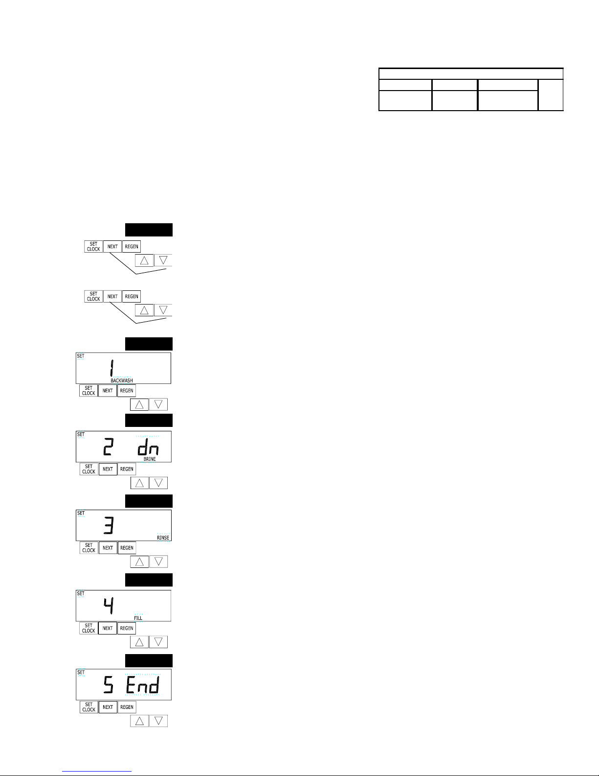
The following is an example of how to set a valve so that when regeneration is initiated BACKWASH occurs first, dn
BRINE occurs second, RINSE occurs third, and FILL occurs fourth.
ß
ß
STEP 1CS
ß
ß
STEP 2CS
STEP 3CS
STEP 4CS
Step 1CS – Press NEXT and simultaneously for 3 seconds until SOFTENING or
FILTERING appears on the display and release. If SOFTENING doesn’t appear, use the
or ∆ button to display it. Then press NEXT and again for 3 seconds and release. If
screen in Step 2CS does not appear in 5 seconds the lock on the valve is activated. To
unlock press , NEXT, ∆, and SET CLOCK in sequence, then press NEXT and simulta-
neously for 3 seconds and release.
Then press NEXT and again for 3 seconds and release.
Step 2CS – Press the or ∆, buttons until BACKWASH appears.
Press NEXT to go to Step 3CS.
Press REGEN if you need to return to the previous step.
Step 3CS - Press the or ∆ buttons until dn BRINE appears.
Press NEXT to go to Step 4CS.
Press REGEN if you need to return to the previous step.
Step 4CS - Press the or ∆ buttons until RINSE appears.
Press NEXT to go to Step 5CS.
Press REGEN if you need to return to the previous step.
ß
STEP 5CS
Step 5CS - Press the or ∆ buttons until FILL appears.
Press NEXT to go to Step 6CS.
Press REGEN if you need to return to the previous step.
ß
STEP 6CS
Step 6CS - Press the or ∆ buttons until END appears.
Press NEXT to exit CYCLE SEQUENCE.
Press REGEN if you need to return to the previous step.
ß
RETURN TO NORMAL MODE
page 3
SOFTENER SYSTEM SETUP
In SOFTENER SYSTEM SETUP you choose the duration for the cycles selected in CYCLE SEQUENCE and specify
other other operating parameters for the system. The upper and lower limits of the allowable values for the cycles are
as follows:
CYCLE SETTING LIMITS
CYCLE OPTIONS UNITS LOWER/UPPER LIMIT DEFAULT
Backwash
Rinse (fast rinse) 6
dn Brine (brine and slow rinse) 6 0
UP Brine (brine and slow rinse) 6 0
Fill (regenerant tank refill) Lbs. 0.1 to 120.0 6.0
Service minutes 1 to 1200 24 0
minutes 1 to 1200
8
Since no time is associated with the END
cycle, the END cycle will not appear in the
SOFTENER SYSTEM SETUP sequence.
Note: Fill is in pounds of salt.
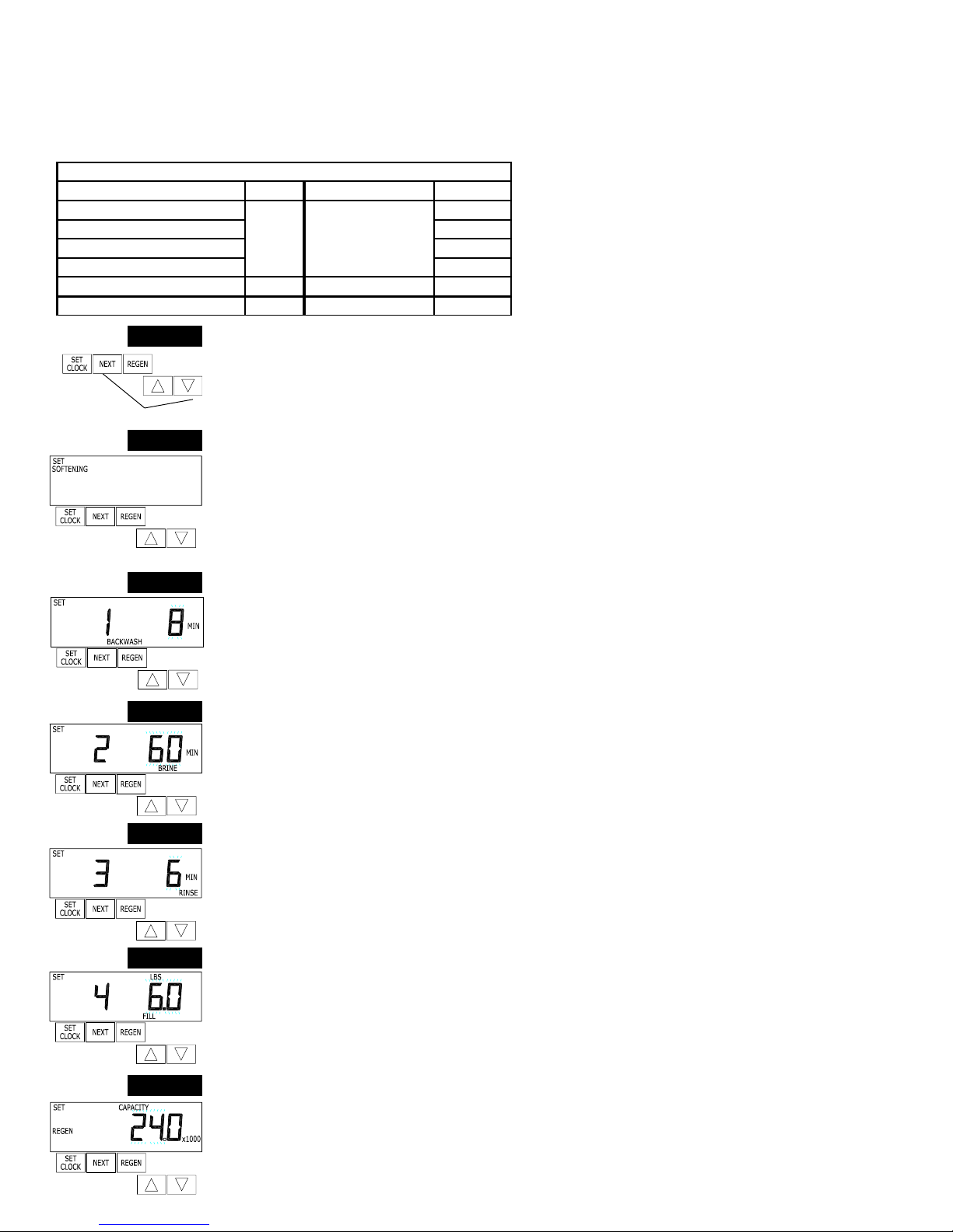
STEP 1S
Step 1S – Press NEXT and simultaneously for 3 seconds and release. If screen in
Step 2S does not appear in 5 seconds the lock on the valve is activated. To unlock press
, NEXT, ∆, and SET CLOCK in sequence, then press NEXT and ∆ simultaneously for 3
ß
STEP 2S
ß
STEP 3S
ß ßß
STEP 4S
STEP 5S
seconds and release.
Step 2S – Choose SOFTENING using the or ∆ button.
Press NEXT to go to Step 3S.
Press REGEN if you want to exit SOFTENER SYSTEM SETUP.
Step 3S – Select the time for the first cycle (which in this example is BACKWASH) using
the or ∆ button.
Press NEXT to go to Step 4S.
Press REGEN if you need to return to previous step.
Step 4S – Select the time for the second cycle (which in this example is dn BRINE) using
the or ∆ button.
Press NEXT to go to Step 5S.
Press REGEN if you need to return to previous step.
NOTE: The display will flash between cycle number and time, and brine direction (dn or
UP).
Step 5S – Select the time for the third cycle (which in this example is RINSE) using the
or ∆ button.
Press NEXT to go to Step 6S.
Press REGEN if you need to return to the previous step.
Step 6S – Select the Lbs. for the fourth cycle (which in this example is FILL) using the
or ∆ button. Press NEXT to go to Step 7S. Press REGEN if you need to return to the
previous step.
STEP 6S
Step 7S – Set Grains Capacity using the or ∆ button. The ion exchange capacity is in
grains of hardness as calcium carbonate for the system based on the pounds of salt that
will be used. Calculate the pounds of salt using the fill time previously selected. The
allowable grains capacity range varies from 5000 to 200,000 grains. The increment in-
ß
crease is 500 for the range from 5000 to 30,000, 1000 for the range of 30,000 to 100,000,
and 2000 for the range of 100,000 to 200,000. Grains capacity is affected by the fill time.
The grains capacity for the selected fill time should be confirmed by testing. The capacity
STEP 7S
and hardness levels entered are used to automatically calculate reserve capacity when
gallon capacity is set to AUTO. Press NEXT to go to Step 8S.
Press REGEN if you need to to return to previous step.
ß
page 4

w
a
c
c
w
g
a
SOFTENER SETUP DETAIL TABLE
This table is to be used as a guide or shortcut to the settings made in Step 3I, 8S, and 9S. For quick programming
use the recommended settings shown in row 3 below in bold italic type.
Gallons
Capacity
AUTO NORMAL oFF
AUTO NORMAL
Any
number
oFF NORMAL Any number
Any
number
AUTO On O oFF
Any
number
Regeneration
Time Option
NORMAL oF F
NORMAL Any number
On O oF F
Day Override
Any number
or 14 day
default
Result
Reserve capacity automatically estimated.
Regeneration occurs when gallons capacity falls below the reserve capacity at the
Time.
Reserve capacity automatically estimated.
Regeneration occurs at the next Regen Set Time when gallons capacity falls belo
capacity...
or the specified number of days between regenerations is reached.
Reserve capacity not automatically estimated. Regeneration occurs at the next Re
when gallons capacity reaches 0
Reserve capacity not automatically estimated.
Regeneration occurs at the next Regen Set Time when the specified number of d
regenerations is reached.
Reserve capacity not automatically estimated.
Regeneration occurs at the next Regen Set Time when gallons capacity reaches 0
number of days between regenerations is reached.
Reserve capacity automatically estimated.
Regeneration occurs immediately when gallons capacity reaches 0.
Time of regeneration is not allowed to be set because regeneration will always oc
gallons capacity reaches 0.
Reserve capacity not automatically estimated.
Regeneration occurs immediately when gallons capacity reaches 0.
Time of regeneration is not allowed to be set because regeneration will always oc
AUTO NORMAL on 0 oFF
AUTO NORMAL on 0 Any number
Any
number
NORMAL on 0 Any number
Reserve capacity automatically estimated.
Regeneration occurs when gallons capacity falls below the reserve capacity at the
Time or regeneration occurs immediately after 10 minutes of no water usage whe
reaches 0.
Reserve capacity automatically estimated.
Regeneration occurs at the next Regen Set Time when gallons capacity falls belo
capacity or the specified number of days between regenerations is reached, or re
immediately after 10 minutes of no water usage when gallon capacity reaches 0.
Reserve capacity not automatically estimated.
Regeneration occurs at the next Regen Set Time when the specified number of d
regenerations is reached, or regeneration occurs immediately after 10 minutes of
when gallon capacity reaches 0.
page 5
SOFTENER SYSTEM SETUP
STEP 8S
ß
STEP 9S
ß
ß
RETURN TO
NORMAL MODE
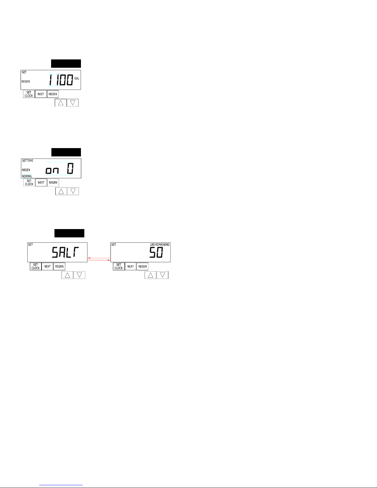
STEP 10S
Step 8S – Set Gallons Capacity using the or ∆ button. If value is set to:
• “AUTO” ...the gallon capacity will be automatically calculated and reserve capacity will be
automatically estimated.
• “oFF”...the regeneration will be based on the day override set
(see Installer Settings Step 3I).
• a specific number (allowable range 20 to 50,000)...the regeneration initiation will be based
on the value specified. The settable increment is 20 for the range 20 to 1000, 50 for the
range of 1000 to 10,000 and 100 for the range of 10,000 to 50,000.
If “oFF” or a specific number is used, hardness display will not be allowed to be set in
Installer Displays Step 2I. Press NEXT to go to Step 9S.
Press REGEN if you need to return to the previous step.
Step 9S – Set Regeneration Time Options using the or ∆ button. If value is set to:
• “NORMAL”...the regeneration will occur at the preset time.
• “on O”...the regeneration will occur immediately when the gallons capacity reaches 0
(zero).
• “NORMAL + on 0”...the regeneration will occur at one of the following:
— the preset time when the gallons capacity falls below the reserve or the specified
number of days between regenerations is reached whichever comes first; or,
— immediately after 10 minutes of no water usage when the gallon capacity reaches 0
(zero).
Press NEXT to go to Step 10S. Press REGEN if you need to return to the previous step.
Step 10S – Set Low Salt Warning using the or ∆ button. If the value is set to:
• “oFF”...no low salt level warning will appear for the user.
• a specific value...“FILL SALT” will flash on the display when
the calculated remaining pounds of salt falls below that level.
Allowable values range form 10 to 400 pounds in 10 pound
increments.
Press NEXT to exit SOFTENER SYSTEM SETUP.
Press REGEN if you ned to return to the previous step.
page 6
BYPASS VALVE
The bypass valve is typically used to isolate the control valve from the plumbing system’s water pressure in order to perform control valve
repairs or maintenance. The 1" full flow bypass valve incorporates four positions including a diagnostic position that allows a service
technician to have pressure to test a system while providing untreated bypass water to the building.
The bypass body and rotors are glass filled Noryl and the nuts and caps are glass filled polypropylene. All seals are self-lubricating EPDM
to help prevent valve seizing after long periods of non-use. Internal o-rings can easily be replaced if service is required.
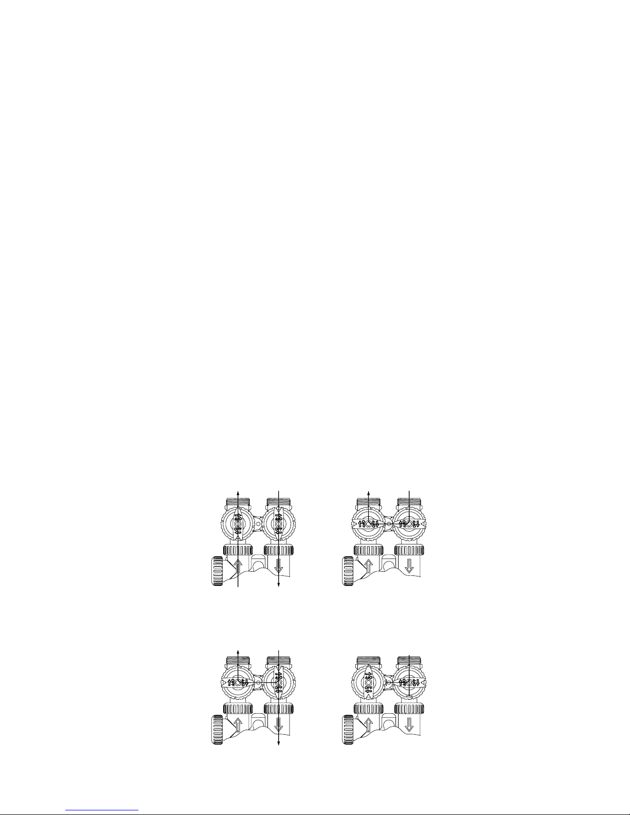
The bypass consists of two interchangeable plug valves that are operated independently by red arrow shaped handles.
The handles identify the direction of flow. The plug valves enable the bypass valve to operate in four positions.
1. Normal Operation Position: The inlet and outlet handles point in the direction of flow indicated by the engraved arrows on the
control valve. Water flows through the control valve for normal operation of a water softener or filter. During the regeneration
cycle this position provides regeneration water to the unit, while also providing untreated water to the distribution system.
(See Figure 1)
2. Bypass Position: The inlet and outlet handles point to the center of the bypass.
The system is isolated from the water pressure in the plumbing system.
Untreated water is supplied to the building. (See Figure 2)
3. Diagnostic Position: The inlet handle points toward the control valve and the outlet handle points to the center of bypass valve.
Untreated supply water is allowed to flow to the system and to the building, while not allowing water to exit from the system to
the building (See Figure 3).
This allows the service technician to draw brine and perform other tests without the test water going to the building.
NOTE: The system must be rinsed before returning the bypass valve to the normal position.
4. Shut Off Position: The inlet handle points to the center of the bypass valve and the outlet handle points away from the control
valve. The water is shut off to the building.
The water treatment system will depressurize upon opening a tap in the building. A negative pressure in the building combined
with the softener being in regeneration could cause a siphoning of brine into the building.
If water is available on the outlet side of the softener or filter it is an indication of water bypassing the system (i.e. a plumbing
cross-connection somewhere in the building). (See Figure 4)
Figure 1
Figure 3
NORMAL OPERATION BYPASS OPERATION
“TREATED” WATER
EXITS
DIAGNOSTIC MODE
SUPPLY WATER
EXITS
SUPPLY WATER
ENTERS
SUPPLY WATER
ENTERS
SUPPLY WATER
EXITS
SHUT OFF MODE
NO WATER
EXITS
SUPPLY WATER
ENTERS
SUPPLY WATER IS SHUT OFF
FROM THE HOUSE AND THE VALVE
Figure 2
Figure 4
page 7

 Loading...