

Page 1
INSTALLATION INSTRUCTIONS: PLEASE LEAVE WITH THE HOMEOWNER
LVH 500 / 510 / 610 / 630 / 720
1000 / 1120 / 1200 / 1310
* These faucets also use supplemental installation instructions along with this booklet.
The red circled numbers (ex: ) relate to the supplemental instructions.
3
* *
*
READ ALL INSTRUCTIONS COMPLETELY BEFORE PROCEEDING WITH
INSTALLATION. INCORRECT INSTALLATION VOIDS THE WARRANTY.
If service is required, rst disconnect power cord and shut off water supply to the EvErHot.
Then call Water, Inc. Service Department at 1-800-322-9283 ext.112 or 115 [Local 310-885-4400 ext.112 or 115].
Removal of the EvErHot without approval may VOID the warranty.
ELECTRICAL REQUIREMENTS:
DO NOT, UNDER ANY CIRCUMSTANCES,
REMOVE THE POWER SUPPLY CORD GROUNDING PRONG!!
For your safety, this appliance must be grounded.
This appliance must be plugged into a mating 3 prong grounding type wall receptacle.
A 15 or 20 Amp circuit is acceptable. This unit requires a constant power supply. It must not be plugged
into the same outlet as the garbage disposal. Water, Inc. offers a dual-plug Air Switch, which is a great
solution for operating an EverHot and garbage disposal. Call our ofce for details. If a properly
grounded outlet is not available, it is the personal responsibility of the customer to have one installed by
a licensed electrician. Outlet must be available in cabinet containing the EvErHot heating tank.
WARNING: An extension cord is not recommended for use with this appliance.
Such use may result in re, electric shock or other personal injury.
INSTALLATION WARNINGS:
NOTE: Warranty DOES NOT COVER problems due to improper installation.
CAUTION: Plumbing connections must comply with all sanitary, safety and local plumbing codes.
1
Do not remove clear plastic tube from inside the faucet spout.
CAUTION: HEATING TANK MUST BE FILLED WITH WATER and the
thermostat turned to the off position before electrical power is connected.
FAILURE TO DO SO WILL CAUSE PERMANENT DAMAGE TO THE UNIT.
Damage to the unit due to “dry start” is NOT covered under the Warranty.
CAUTION: Do not use pipe sealing compounds. These compounds will cause an
unpleasant taste or odor to the water. These compounds are not needed with the
special ENCLOSED ttings used with this product.
SAVE THESE INSTALLATION INSTRUCTIONS
ater Inc
800-322-9283 • waterinc.com
M - F 8 AM - 5 PM (PST)
Please make sure you review #13 (After-Installation EverHot Tips on page 3)
AND LEAVE WITH THE HOMEOWNER.
to ensure proper long-term care of your new EverHot system.
EverHot mark is used under license from Bradford White Corp. • Body Glove is a registered trademark of Body Glove International, LLC. • Teon is a registered trademark of E.I. Dupont de Nemours & CO. Willmington, DE 19898 U.S.A.
1
Page 2
PARTS LIST
1-USERS’ GUIDE AND WARRANTY INFORMATION SHEET
1- EvErHot Faucet with bag containing: Escutcheon, Vinyl Gasket & Flat Metal Washer (Fig. 1) - or - C-Shaped Metal Washer (Fig. 1A),
Spacer, Lock Washer, Nut, and Mounting Nut Wrench.
1- EvErHot Tank Assembly
1- FITTING PACKAGE CONTAINING: 1- Mounting Bracket, 2- Screws for Mounting Bracket, 1- Allen Wrench,
and 1- 3/8” X 5/16” Quick Connect Reducing Union
2
INSTALLATION INSTRUCTIONS
* These faucets also use supplemental installation instructions along with this booklet.The red circled numbers (ex: ) relate to the supplemental instructions.
*****************************************************************************************************************************
Please note that additional 1/4” tubing and other ttings may be needed for the installation and are not
provided with the product. Do not use pipe dope or Teon® tape on any tting for this installation.
If service is required, rst disconnect the power cord and shut off water supply to the EvErHot. Then call Water, Inc.
READ THESE INSTRUCTIONS CAREFULLY BEFORE PROCEEDING WITH
INSTALLATION. CALL WATER, INC. SERVICE DEPARTMENT IF YOU HAVE ANY
1.
DO NOT PLUG IN TANK OR TURN ON THE THERMOSTAT CONTROL KNOB
FOR MODELS LVH 500 / 510 / 610 / 630 / 720*/ 1000 / 1120*/ 1200*/ 1310
3
Call the Water, Inc. Service Department at 1-800-322-9283 [Local 310-885-4400 ext. 112 or 115]
if you need assistance with this installation or service.
Removal of the EvErHot without prior approval may void the warranty.
QUESTIONS REGARDING THE INSTALLATION OF THIS PRODUCT.
UNTIL YOU ARE TOLD TO DO SO IN THESE INSTRUCTIONS.
2. A 1 1/4” hole in your sink is needed, (or 1 3/8” if installing optional reverse osmosis airgap module) If you need
to drill a hole in your sink we suggest you consult a qualied installer. Try to position the EvErHot faucet so that
your existing/new sink faucet does not interfere with the EvErHot faucet.
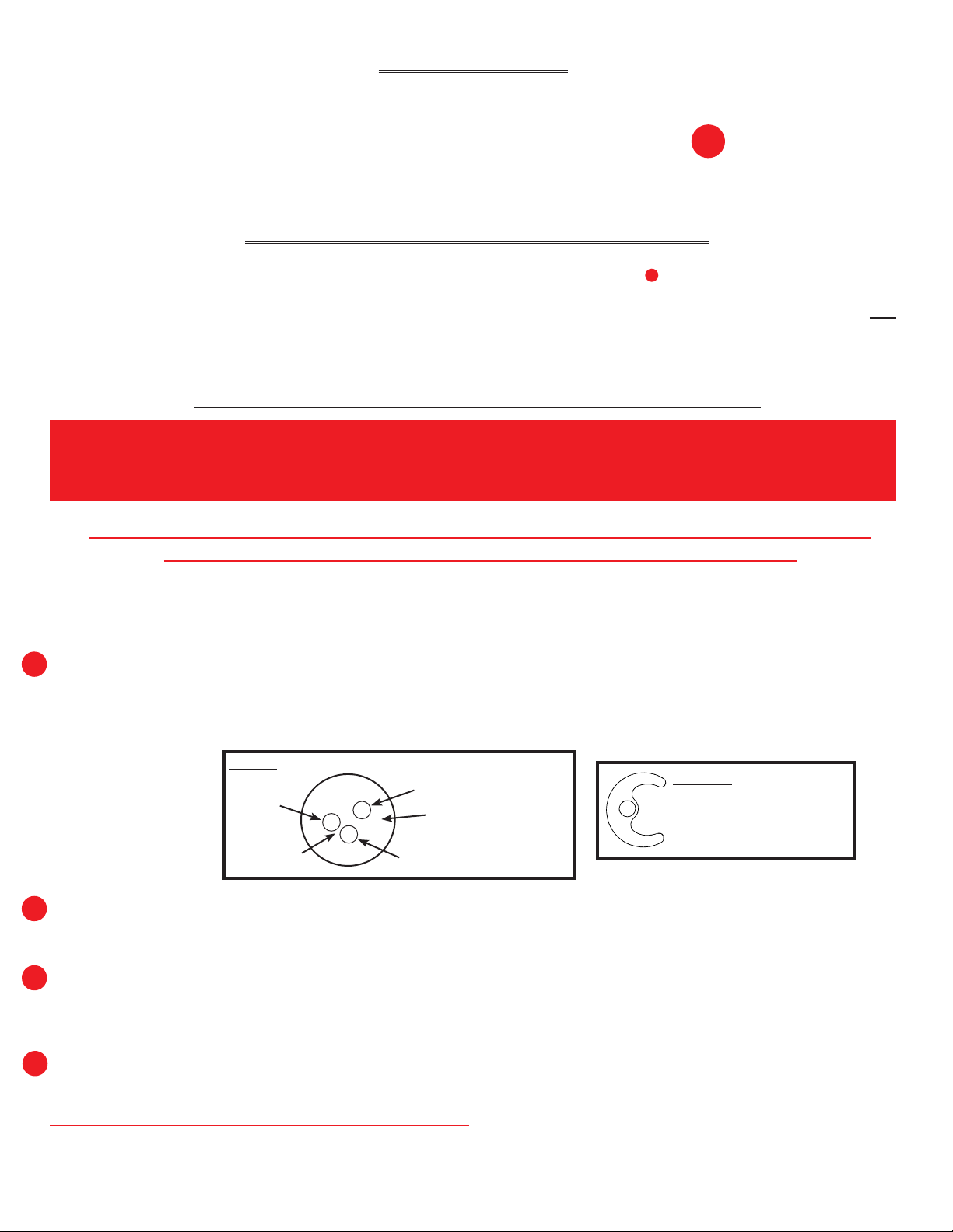
3. If you have a Vinyl Gasket and a Flat Metal Washer (Fig.1): Assemble escutcheon and vinyl gasket over the
3
threaded faucet shank and insert assembly into sink hole. See Fig.1 for tube placement in gasket holes. Vinyl
gasket must be used. DO NOT USE plumber’s putty.
If you have a C-Shaped Metal Washer (see Fig.1A to conrm that you have the C-Shaped Washer): Assemble
escutcheon that has a built-in gasket over the threaded faucet shank and insert assembly into sink hole. DO NOT
USE plumber’s putty.
FIG. 1 if you have a Vinyl Gasket and Flat Metal Washer
RED
(Note closely
spaced holes)
BLUE
This is the vinyl
escutcheon gasket,
and this is how you place
the tubes through it
CLEAR/WHITE
FIG. 1A
This is the C-Shaped Washer.
If you have the C-Shaped Washer,
then you also have a built-in
escutcheon gasket.
4. From underneath the sink install the Flat Metal Washer OR the C-Shaped Metal Washer, spacer*, friction ring*,
4
lock washer, and nut onto the 5/16” clear/white Teon® tube and tighten nut on threaded shank.
*spacer & friction ring are only included with models LVH 500, 510, 610, and 1310
5. Loosen set screw at the rear of the faucet body using the allen wrench provided. (LVH 500, 510,
5
610 & 630 dual lever faucets only). Adjust spout to the desired position and tighten set screw. (DO NOT OVER-
TIGHTEN) Do not move or adjust the spout after tightening the set screw, as any movement of the spout after
installation could cause a leak or damage to the unit.
6. Position the heating tank assembly vertically beneath the faucet so that the 5/16” Teon® tube
6
from the spout reaches the center stainless steel tube on the tank and the tank touches the wall.
With a pencil, mark the wall at the top of the tank. Set the tank to one side. Mark a second line 2 1/4”
below the rst line. Install the bracket with bottom of the bracket even with the lower line. Hang tank on bracket.
DO NOT PLUG THE TANK ELECTRIC CORD IN YET!
7. Connect red tube that originates beneath the hot lever to the 1/4” integral push-to-connect tting at the top right
rear corner of the tank. See Fig.2 for tting tips, and see SCHEMATIC on PAGE 4 for undersink layout.
page 2
Page 3

FIG. 2 The ease and simplicity of using enclosed ttings. Collets and O-rings are readily replaceable - a useful feature in cases
of misuse or accidental damage. DO NOT USE A TUBE INSERT WITH THESE FITTINGS.
Simply push-in-tube to attach
Note: Tube must be cut squarely
and pushed straight in.
Tube is secured in position.
Push in and hold collet
while gently pulling tube to release.
8. Connect the blue tube that originates beneath the cold handle to the cold water supply. Do not use
a brass compression ferrule on plastic tubing (Use plastic ferrule). Brass ferrules can cut plastic tube and
cause ooding. DO NOT turn on water yet!
9. A quality Drinking Water System, such as a Body Glove Water Filter System, will prolong the life of this
appliance and increase the enjoyment of the water being dispensed to the EvErHot owner. Should a chiller,
such as the EvErCold®, be used with the EvErHot, the undersink chiller should be installed in the line after
the drinking water system and before the EvErHot faucet connection (blue tube). SEE SCHEMATIC PAGE 4.
Note: Chiller is not applicable if installing the models 500H, 510H, 610H, and 630H (HOT ONLY).
10. Connect 5/16” Teon
®
tubing from faucet to top center outlet tube on the tank using the
5/16” x 3/8” reducing union provided. Reducing union MUST be used. DO NOT insert Teon® tube directly into tank outlet tube. Tubing should be cut squarely to proper length using a sharp knife or di-
agonal side cutting pliers. DO NOT PULL, PUSH, REMOVE OR OTHERWISE ATTEMPT TO MOVE OR
ADJUST TEFLON TUBE (CLEAR/WHIE PLASTIC TUBE INSIDE THE FAUCET SPOUT AND THROUGH
BODY). If tube is too short to reach tank, an extension tube and special coupling is available from the
Water, Inc. Service Department (800) 322-9283. Insert end of tubing fully into blue collet of special tting.
IT IS IMPERATIVE THAT THE TEFLON TUBING IS NOT LEFT IN A KINKED POSITION. WATER FLOWING INTO HEATING TANK WITH TUBE KINKED OR OTHERWISE OBSTRUCTED WILL CAUSE PERMANENT DAMAGE TO INTERNAL TANK PARTS AND VOIDS PRODUCT WARRANTY . Positioning tank directly
beneath faucet and cutting tube to proper length will help avoid kinks in Teon tubing. Note: If needed,
a special 90°adaptor tting is available from the Water, Inc. Service Department for a nominal charge.
11. Turn on water supply and ip up or open valve on the HOT (red dot) lever on the EvErHot faucet. NOTE:
The tank can
only be lled by operating the hot (red dot) lever. Do not operate both levers to ll tank. This allows the
heating tank to ll with water. When water ows from faucet into the sink, ip lever off or close valve and
inspect for leaks now that faucet is pressurized. Tighten any leaking ttings.
NOTE: FAILURE TO COMPLETELY FILL HEATING TANK WITH WATER BEFORE CONNECTING POWER
CORD TO OUTLET WILL CAUSE PERMANENT DAMAGE TO HEATING ELEMENT AND TANK SEALS
(VOIDING WARRANTY) AS WELL AS CAUSE AN UNPLEASANT TASTE AND BLACK SPECKS IN THE
7
WATER.
11A. SPECIAL NOTE: When installing EvErHot with a new reverse osmosis (R.O.) type water
lter, several hours of R.O. system operation may be needed to produce enough water to ensure
adequate lling of the EvErHot tank.
12. Plug power supply cord into a properly grounded 115V wall outlet. Turn thermostat knob clockwise to the
highest setting. Maximum temperature will be reached in about 10-15 minutes and dispenser will be ready for
use. Lower the temperature setting slightly if you ever notice excessive vapor or boiling noise during
the heating cycle. The thermostat knob controls the water temperature, not the water delivery. To raise or lower
the water temperature, adjust the thermostat knob accordingly.
Some dripping from the spout during the heating cycle, especially upon initial start-up, is normal and is due
to the expansion of water in the heating tank.
13. After-Installation EverHot Tips for Long-Term Care:
• If EvErHot system will be unused for more then 5 consecutive days, turn thermostat knob to
off position, or unplug tank to prevent damage due to excessive evaporation of water.
• If you shut off the water supply to your EvErHot tank, for example to change your water lter,
turn water supply back on SLOWLY, do not “rush” the water back into your EvErHot tank.
• Read the Decorative Faucet Finish Care sheet to learn how to clean and care for your EvErHot faucet.
3
Page 4

WATER FILTRATION SYSTEM:
BODY GLOVE™ ANY MODEL
page 4
800-322-9283 • waterinc.com
(NOT DRAWN TO SCALE)
WALL RECEPTACLE
GROUNDING TYPE
REQUIRED.
PROVIDED WITH THE EVERHOT
3/8”X 5/16” REDUCING UNION
3 PRONG
CARTRIDGE AND CABINET
FLOOR FOR CARTRIDGE
CHANGE
EVERCOLD
(NOT INCLUDED WITH EVERHOT)
®
CHILLER:
WIC-400S OPTIONAL
INSTALLATION SCHEMATIC
2” REQUIRED BETWEEN
BOTTOM OF FILTRATION
EVERHOT
THE WATER SUPPLY FOR THE
ENTIRE SYSTEM IS FROM
THIS COLD WATER RISER
FILTER
INLET
FILTER
OUTLET
WATER
CHILLER
INLET
COLD WATER GOES FROM FILTER
DIRECT TO EvErHot FAUCET
NOTE: IF WATER CHILLER
IS NOT USED, INCOMING
OTHER WATER USING APPLIANCES LIKE
ICE MAKERS, COFFEE MAKERS, ETC.
CONNECT TO THIS LINE BY USING
Water Inc
(BLUE TUBE)
1/4” TEE(S)
CHILLED WATER SUPPLY LINE
RECOMMEND INSULATING
BLUE PLASTIC TUBE*
AND FITTINGS MAY BE REQUIRED
ADDITIONAL 1/4” O.D. TUBING
** IF CLEAR PLASTIC TUBE IS
PULLED OUT OF FAUCET BODY
EVEN PARTIALLY, DAMAGE WILL
OCCUR CAUSING WATER LEAK.
PLEASE NOTE THAT DAMAGE TO
UNIT IS NOT COVERED UNDER
PRODUCT WARRANTY.
LEAVE SPACE FOR AIR
CIRCULATION AROUND CHILLER
(ALL SIDES)
NOT USE BRASS FERRULE ON
PLASTIC TUBE AS LEAK OR
FLOODING MAY RESULT. DO NOT
USE A TUBE INSERT.
WATER CHILLER
OUTLET
TO STAINLESS STEEL TANK TOP
CENTER TUBE USING REDUCTION
FITTING (PROVIDED)
DO NOT KINK
OFF/ON THERMOSTAT
IMPORTANT:
* USE ONLY DELRIN (PLASTIC)
FERRULE OR PUSH-TO-CONNECT
FITTING ON PLASTIC TUBE. DO
CONTROL KNOB
TEFLON TUBING
TO WATER SUPPLY
HOT WATER LEVER
COLD WATER LEVER
TEFLON (CLEAR PLASTIC) TUBE**
RED PLASTIC TUBE*
TO 1/4 INTEGRAL FITTING ON TANK
(your tank may be a different shape)
(LVH-500 FAUCET PICTURED ABOVE)
INSTANT HOT:
EvErHot tank
W-192 (Rev. 7/2014)
 Loading...