

Page 1
HOUSEPURE HP01 & HP02
®
Installation, Startup and
Troubleshooting Guide
Page 2

Table of Contents
Assembly
Equipment Overview ....................................................................................................... 1
Installation Overview ....................................................................................................... 2
Assembling the Filter - basic connections .................................................................3 & 4
Start-Up and Programming
Filter Start-Up - programming .......................................................................................... 5
Filter Start-Up - tank fill and initial flush .....................................................................6 & 7
Filter Start-Up - final steps. .............................................................................................. 8
Page 3
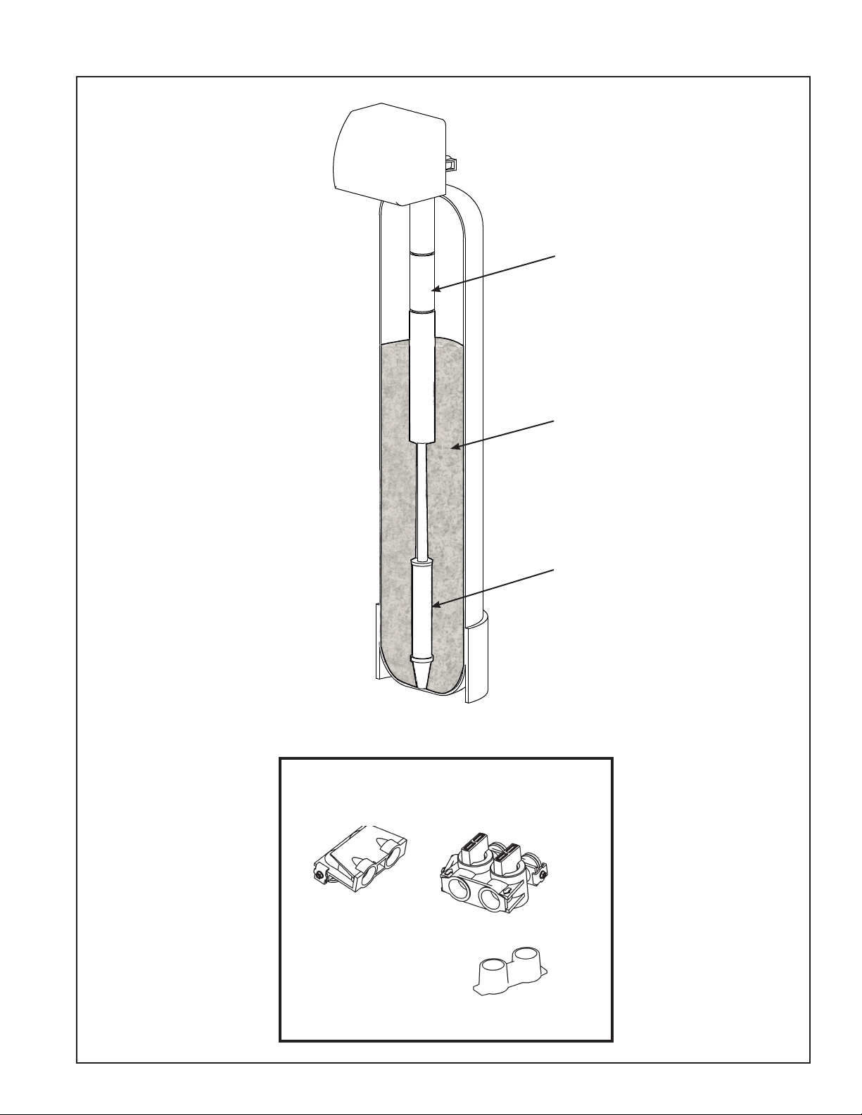
Equipment Overview
Installation Manual Page 1
KDF MediaGuard
Removes Chlorine
and extends the
life of the Activated
Carbon.
Premium Granular
Activated Carbon
Removes taste, odors
and THM’s.
Installation Parts
Bypass Elbow
ScaleFree Water
Conditioner
Reduces Hard
Water Scaling.
Bypass Valve
Plastic Yoke
Page 4

Installation Overview
Installation Manual Page 2
Connection Overview
Outlet: 1” NPT (To water heater and prefilter inlet)
Inlet: 1” NPT (From domestic water source)
Drain: 1/2” hose (To indirect drain (4 gpm))
62”
Electrical Requirements
Power supply
110VAC, 60HZ, 2A
Plumbing Requirements
Inlet connection
Inlet pressure
Max Temperature
Outlet connection
Drain connection
Drain flow
1” NPT
20 psi min., 125 psi max.
110°F
1” sweat
1/2” ID hose
4 gpm max.
Filter Specifications
Control valve
Media tank
Media volume
Fleck HP2510 SE
10” diameter x 54” tall
1.5 cubic foot per tank
10.0”
Page 5

Assembling the Filter - basic connections
Installation Manual Page 3
1
a. Remove the tank from the box.
b. Place the tank on a level surface near the
nal installation position.
c. Place the tank within 8 feet of a 110VAC
outlet and within 10 feet of a drain..
2
Bypass Valve
a. Remove the package of components, parts
and tubing from the box.
b. Install the bypass valve onto the control
valve assembly as shown above.
3
Plastic Yoke
a. Attach the plastic yoke to the bypass valve.
b. Connect the pipes to the 1” male NPT t-
tings on the plastic yoke.
4
Secure pipes to wall so that
their weight is fully supported.
Install a barb fitting into
the drain port (1/2” NPT).
a. Secure the piping to the wall or other
structure. The valve must not be used to
support the weight of the pipes.
b. Install a barb tting in the drain port. Con-
nect a 1/2” ID hose to the barb tting and
run it to the drain. Provide an airgap where
the drain line connects to the drain. Secure
the drain line connection.
Page 6

Filter Start-Up - programming
Installation Manual Page 4
13 14
a
b
a. Connect bell, thermostat or sprinkler wire,
(2 conductor, solid) to the screw terminals
on the transformer.
b. Connect the wire from the transformer
to the blue wire and white wire (located
behind the electronic control panel, using
wire nuts or crimp connectors.
Connect wire to the
screw terminals on
the transformer.
Connect the
transformer to
the blue wire and
white wire found
behind this panel.
Plug the transformer into an unswitched
110VAC outlet. Secure the transformer to the
outlet with the screw provided.
15
When powered up, the controller display will
display the Time Of Day. To Set the time:
a. Press the UP or DOWN arrow button to
change the time displayed.
16
NOTE:
The valve is fully programmed at the
factory for backwash frequency, duration and time of day. The system is now
ready to be filled with water and backwashed.
!
CAUTION:
Read the following instructions carefully
first. The start-up procedure must be followed correctly to ensure the best performance from the system and to prevent
any possible problems.
DO NOT OPEN THE INLET WATER
SUPPLY VALVE UNTIL INSTRUCTED TO DO SO!
b. When the correct time is reached, release
the UP or DOWN arrow button.
Page 7

Filter Start-Up - Tank Fill and Initial BackWash
Installation Manual Page 5
17
Bypass Valve in
Bypass Position
Put the Bypass Valve in the Bypass Position:
18
CYCLE button
Cycle the valve to Cycle 3, Rapid Rinse.
a. Press and Hold the Cycle button for about
5 seconds until the valve activates. The
Valve will stop at Cycle 1 (Backwash)
b. Press the Cycle button to advance to Cycle
3, Rapid Rinse.
19 20
a
b
Inlet Valve
a. Slowly open the main water supply valve.
Flush the piping for a few minutes.
b. After ushing the pipes, slowly open the
inlet valve on the bypass valve. Allow the
tank to ll slowly. Continue lling slowly
until a clear, steady stream comes out of
the drain line then close the inlet valve on
the bypass.
a. Press the Cycle button once to return to the
b. Let the system stand for 15 to 20 minutes
15:00
Service position.
to allow the media to absorb the water.
Page 8

Filter Start-Up - Tank Fill and Initial BackWash
Installation Manual Page 6
21 22
Inlet Valve
Open
a. Open the Inlet Valve on the Bypass.
b. Press and hold the Cycle button to put the
valve into Backwash.
a. Allow the system to backwash until the
b. Press the Cycle button to advance the valve
a
b
drain runs clear or until the end of the
backwash cycle, whichever comes rst.
to the Rapid Rinse position. (The valve will
advance automatically after 9 minutes of
Backwash.)
23 24
Note Air-Gap
a
b
a. Monitor the water owing to drain dur-
ing Rapid Rinse. You want to be sure that
the water is clear. Capture some water in a
glass and inspect it to ensure that there are
no black particles.
a. If the water is not clear at the end of the
a
Rapid Rinse cycle, put the system in Backwash again by pressing and holding the
cycle button. Repeat steps 21 and 22 until
the water runs clear during Rapid Rinse.
b. Once the water is clear, you can advance
the valve to the service position.
Page 9

Filter Start-Up - final steps
25 26
Installation Manual Page 7
a. Cycle valve to the Service Position
a. Open the Outlet Valve on the Bypass.
(The illustration above show the bypass
valve in the Service Position with both
valves open.)
27 28
a. The system is now in service.
b. Go into the home and open cold water
taps throughout the home to ush out
any air bubbles and ll the pipes with
treated water.
a. Check the system for leaks. Correct if
necessary.
 Loading...