

Water Heater Innovations 196284-001 User Manual
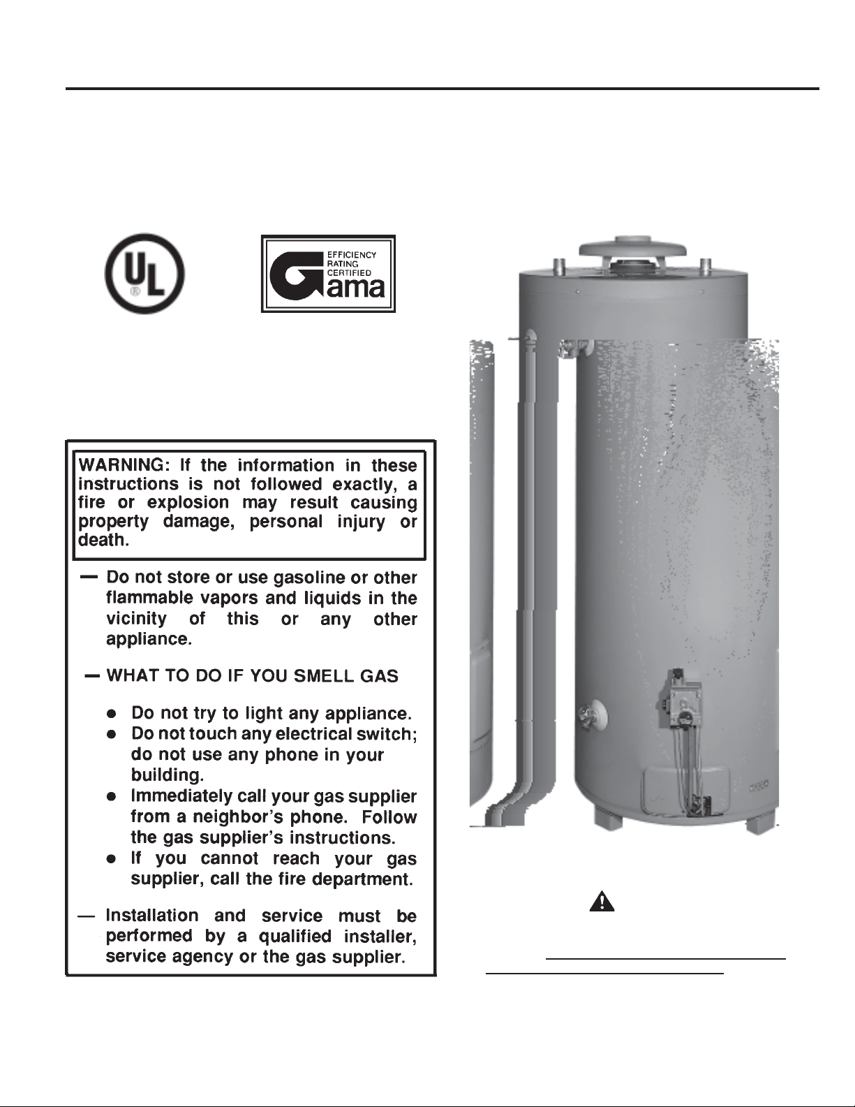
COMMERCIAL GAS W ATER HEATER
Glass-Lined Tank-Type Water Heater
• INSTALLATION • OPERATION • SERVICE • MAINTENANCE
Thank you for buying this energy efficient water heater. We
appreciate your confidence in our products.
PRINTED IN U.S.A. 1004
CAUTION
TEXT IN BLACK BOLD TYPE OR UNDERLINED
CONTAINS INFORMATION RELATIVE TO YOUR
SAFETY. PLEASE READ THOROUGHLY BEFORE
INST ALLING AND USING THIS APPLIANCE.
PLACE THESE INSTRUCTIONS ADJACENT TO HEA TER
AND NOTIFY OWNER TO KEEP FOR FUTURE REFERENCE.
PART NO. 196284-001
1
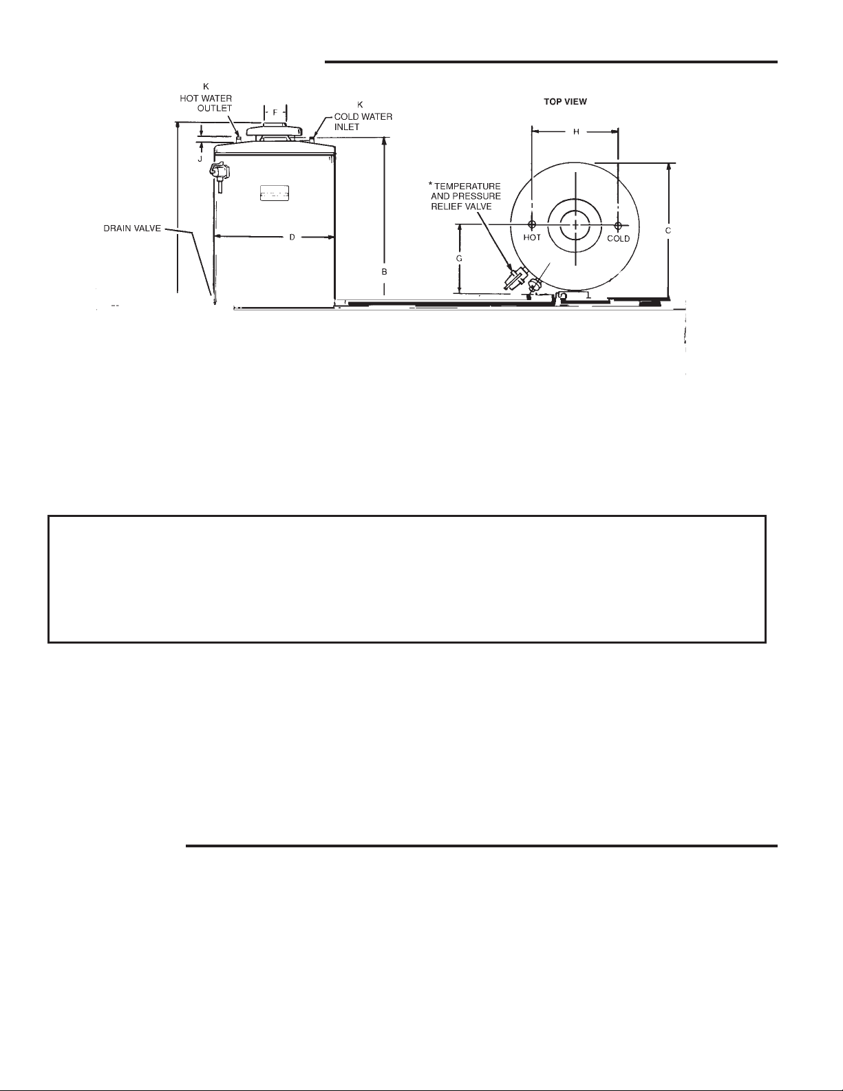
ROUGH-IN DIMENSIONS
FIGURE 1
UNDERSTANDING YOUR MODEL
Model Designator : Sample ***75 75 NE
*** = Letter Designator
75 = Gallons (Capacity of Unit)
75 = kBTU (Approx. Rating of Unit)
N = Gas Type (Natural)
E = 3 Year Warranty
DIMENSIONS
Model Units A B C D E F G H J K L M
75 Inches 61 1/8 58 1/2 29 11/16 26 1/2 15 3/16 4 14 1/2 16 1 1/4 1 1/2 11 15/16
Natural & LP C M 155.25 148.6 75.4 67.3 38.6 10.2 39.4 40.6 3.2 NPT NPT 30.3
100 Inches 69 3/4 66 1/2 29 11/16 26 1/2 15 3/16 4 14 1/2 16 1 1/4 1 1/4 1/2 11 15/16
Natural C M 177.2 168.9 75.4 67.3 38.6 10.2 39.4 40.6 3.2 NPT NPT 30.3
100 Inches 68 5/8 66 1/2 30 15/16 27 3/4 15 3/16 4 15 3/4 16 1 1/4 1 1/4 1 /2 11 15/16
LP CM 174.3 168.9 78.59 70.5 38.6 10.2 40.0 40.6 3.2 NPT NPT 30.3
FOREWORD
The design of models ***-75 and 100 comply with the latest version
of ANSI Z21.10.3-CSA 4.3 as automatic storage or automatic
circulating tank type water heaters.
local area where the installation is to be made. These shall be
carefully followed in all cases. Authorities having jurisdiction
should be consulted before installations are made.
Installation diagrams are found in this manual. These diagrams
will serve to provide the installer with a reference for the materials
and method of piping necessary. It is highly essential that all
water and gas piping be installed as shown on the diagrams.
In addition to these instructions, the equipment shall be installed
in accordance with those installation regulations in force in the
The installation must conform to these instructions and the local
code authority having jurisdiction. In the absence of local codes,
the installation must comply with the latest editions of the National
Fuel Gas Code, ANSI Z223.1/NFPA 54. This publication is available
from the Canadian Standards Association, 8501 East Pleasant
V alley Road, Cleveland, OH 44131, or the National Fire Protection
Association, 1 Batterymarch Park, Quincy, MA 02269.
2

TABLE OF CONTENTS
Page
ROUGH-IN DIMENSIONS ................................................................. 2
FOREWORD.................................................................................... 2
GENERAL SAFETY INFORMA TION ................................................ 3-4
Precautions................................................................................. 3
Chemical Vapor Corrosion ......................................................... 3
Improper Combustion.................................................................. 3
Liquid Petroleum Models ............................................................. 3-4
Extended Non-use Periods ........................................................ 4
Insulation Blankets...................................................................... 4
Circulating Pump ......................................................................... 4
INSTALLA TION INSTRUCTIONS ...................................................... 4-9
Required Ability........................................................................... 4
Locating The Heater ................................................................... 4-5
High Altitude Installations ........................................................... 5
Clearances ................................................................................. 5
Hard Water ................................................................................. 5
Air Requirements........................................................................ 5-6
Water (Potable) Heating and Space Heating ............................. 6
Venting........................................................................................ 6-7
Thermometers (Not Supplied) .................................................... 7
Relief Valve ................................................................................. 7
Gas Piping................................................................................... 7-8
Gas Pressure Regulator ............................................................ 9
OPERA TION..................................................................................... 9-13
Page
To Operate The Water Heater .................................................... 9
Purging ........................................................................................ 9
Lighting Instructions ................................................................... 10-11
T emperature Regulation ............................................................. 12
Check Venting ............................................................................ 12-13
High Temperature Limit Switch................................................... 13
SERVICE INFORMA TION ................................................................. 13-14
Pilot and Main Burner.................................................................. 13
Checking Gas Input .................................................................... 13-14
Vent System ............................................................................... 14
Relief Valve ................................................................................. 14
Hot Water Odor .......................................................................... 14
Anode Rod Inspection ................................................................ 14
Winter Protection ........................................................................ 14
Replacement Parts ..................................................................... 14
PREVENTIVE MAINTENANCE ......................................................... 15-16
Recommended Procedure For Periodic Removal Of Lime
Deposits From Tank Type Commercial Water Heaters .............. 15
Deliming Solvents ....................................................................... 15
Tank Cleanout Procedure ........................................................... 15-16
CHECKLIST ..................................................................................... 16-17
NOTES ............................................................................................ 18
LIMITED WARRANTY...................................................................... INSERT
GENERAL SAFETY
INFORMATION
PRECAUTIONS
DO NOT USE THIS APPLIANCE IF ANY P ART HAS BEEN UNDER
WATER. Immediately call a qualified service technician to inspect
the appliance and to replace any part of the control system and any
gas control which has been under water.
IF THE UNIT IS EXPOSED TO THE FOLLOWING, DO NOT
OPERATE HEA TER UNTIL ALL CORRECTIVE STEPS HA VE BEEN
MADE BY A QUALIFIED SERVICEMAN.
1. EXTERNAL FIRE.
2. DAMAGE.
3. FIRING WITHOUT WA TER.
4. SOOTING
CHEMICAL VAPOR CORROSION
WARNING
CORROSION OF THE FLUEWA YS AND VENT SYSTEM MA Y OCCUR
IF AIR FOR COMBUSTION CONT AINS CERTAIN CHEMICAL V APORS.
SUCH CORROSION MAY RESULT IN FAILURE AND RISK OF
ASPHYXIA TION.
Spray can propellants, cleaning solvents, refrigerator and air
conditioning refrigerants, swimming pool chemicals, calcium and
sodium chloride (water softener salt), waxes, and process
chemicals are typical compounds which are potentially corrosive.
Do not store products of this sort near the heater . Also, air which is
brought in contact with the heater should not contain any of these
chemicals. If necessary, uncontaminated air should be obtained
from remote or outside sources. The limited warranty is voided
when failure of water heater is due to a corrosive atmosphere.
(Refer to the limited warranty for complete terms and conditions.)
IMPROPER COMBUSTION
WARNING
ATTIC AND/OR EXHAUST FANS OPERATING ON THE PREMISES
WITH A WATER HEA TER CAN RESUL T IN CARBON MONOXIDE
POISONING AND DEATH.
OPERA TION OF THESE FANS CAN PRODUCE A NEGA TIVE DRAFT
IN THE AREA OF THE WATER HEATER PREVENTING THE
PRODUCTS OF COMBUSTION FROM EXHAUSTING THROUGH
THE CHIMNEY OR VENT PIPE.
The venting of the water heater should be inspected by a qualified
service technician at the time of installation and periodically
thereafter to ensure a down-draft condition does not exist.
DO NOT OBSTRUCT THE FLOW OF COMBUSTION AND
VENTILATING AIR. ADEQUATE AIR FOR COMBUSTION AND
VENTILATION MUST BE PROVIDED FOR SAFE OPERA TION.
LIQUID PETROLEUM MODELS
Water heaters for propane or liquefied petroleum gas (LPG) are
different from natural gas models. A natural gas heater will not
function safely on LP gas and no attempt should be made to
convert a heater from natural gas to LP gas.
LP gas must be used with great caution. It is highly explosive
and heavier than air . It collects first in the low areas making it s
odor difficult to detect at nose level. If LP gas is present or even
suspected, do not attempt to find the cause yourself. Go to a
neighbor's house, leaving your doors open to ventilate the house,
then call your gas supplier or service agent. Keep area clear
until a service call has been made.
At times you may not be able to smell an LP gas leak. One cause
is odor fade, which is a loss of the chemical odorant that gives
LP gas its distinctive smell. Another cause can be your physical
condition, such as having a cold or diminishing sense of smell
with age. For these reasons, the use of a propane gas detector
is recommended.
3

IF YOU EXPERIENCE AN OUT -OF-GAS SITUATION, DO NOT TR Y TO
RELIGHT APPLIANCES YOURSELF, ask your LP delivery person to
relight pilots for you. Only trained LP professionals should conduct
the required safety checks in accordance with industry standards.
EXTENDED NON-USE PERIODS
WARNING
HYDROGEN GAS CAN BE PRODUCED IN A HOT W A TER SYSTEM
SERVED BY THIS HEA TER THAT HAS NOT BEEN USED FOR A LONG
PERIOD OF TIME (GENERALLY TWO WEEKS OR MORE).
HYDROGEN GAS IS EXTREMEL Y FLAMMABLE. T o reduce the risk
of injury under these conditions, it is recommended that the hot
water faucet be opened for several minutes at the kitchen sink
before using any electrical appliance connected to the hot water
system. If hydrogen is present, there will probably be an unusual
sound such as air escaping through the pipe as the water begins
to flow. THERE SHOULD BE NO SMOKING OR OPEN FLAME NEAR
THE FAUCET AT THE TIME IT IS OPEN.
INSULATION BLANKETS
Insulation blankets available to the general public for external use
on gas water heaters are not approved for use on your commercial
water heater. The purpose of an insulation blanket is to reduce the
standby heat loss encountered with storage tank water heaters.
Your commercial water heater meets or exceeds the ASHRAE/IES
90.1b-1999 standards with respect to insulation and standby loss
requirement making an insulation blanket unnecessary.
WARNING
Should you choose to apply an insulation blanket to this heater,
you should follow these instructions. Failure to follow these
instructions can result in fire, asphyxiation , serious personal
injury or death.
• Do not apply insulation to the top of the water heater , as this
will interfere with safe operation of the draft hood.
• Do not cover the outer door, thermostat or temperature &
pressure relief valve.
• Do not allow insulation to come within 2" (5cm) of the floor to
prevent blockage of combustion air flow to the burner.
• Do not cover the instruction manual. Keep it on the side of
the water heater or nearby for future reference.
• Do obtain new warning and instruction labels from your
commercial water heater company for placement on the
blanket directly over the existing labels.
• Do inspect the insulation blanket frequently to make certain
it does not sag, thereby obstructing combustion air flow.
CIRCULATING PUMP
A circulating pump is used when a system requires a circulating
loop or there is a storage tank used in conjunction with the heater.
Install the system in accordance with the latest version of the
National Electric Code ANSI/NFPA No. 70.
4

Drain pans suitable for these heaters are available from your
distributor or Apcom Inc., 125 Southwest Parkway, Franklin,
TN 37065 or contact them by phone, 615-794-5574 or fax
615-791-0660.
Water heater life depends upon water quality, water pressure and
the environment in which the water heater is installed. Water heaters are sometimes installed in locations where leakage may result in property damage, even with the use of a drain pan piped to
a drain. However, unanticipated damage can be reduced or prevented by a leak detector or water shutoff device used in conjunction with a piped drain pan. These devices are available from
some plumbing supply wholesalers and retailers, and detect and
react to leakage in various ways:
• Sensors mounted in the drain pan that trigger an alarm or turn
off the incoming water to the water heater when leakage is
detected.
• Sensors mounted in the drain pan that turn off the water supply
to the entire home when water is detected in the drain pan.
• Water supply shutoff devices that activate based on the water
pressure differential between the cold water and hot water pipes
connected to the water heater.
• Devices that will turn off the gas supply to a gas water heater
while at the same time shutting off its water supply.
For appliance installation locations with elevations above 2000
feet (610 meters), refer to HIGH AL TITUDE INST ALLA TIONS section
of this manual for input reduction procedure.
HIGH AL TITUDE INST ALLATIONS
WARNING
INSTALLATIONS ABOVE 2000 FEET (610 METERS) REQUIRE
REPLACEMENT OF THE BURNER ORIFICE IN ACCORDANCE WITH
SECTION 8.1.2 OF THE NA TIONAL FUEL GAS CODE (ANSI Z223.1).
FAILURE T O REPLACE THE ORIFICE WILL RESUL T IN IMPROPER
AND INEFFICIENT OPERATION OF THE APPLIANCE RESULTING IN
THE PRODUCTION OF INCREASED LEVELS OF CARBON MONOXIDE
GAS IN EXCESS OF SAFE LIMITS WHICH COULD RESULT IN
SERIOUS PERSONAL INJURY OR DEATH.
You should contact your gas supplier for any specific changes
which may be required in your area.
As elevation above sea level is increased, there is less oxygen per
cubic foot of air. Therefore, the heater input rate should be reduced
at high altitudes for satisfactory operation with the reduced oxygen
supply. Failure to make this reduction would result in an overfiring
of the heater causing sooting, poor combustion and/or
unsatisfactory heater performance.
Ratings specified by manufacturers for most appliances apply for
elevations up to 2000 feet (610m). For elevations above 2000 feet
(610m), ratings must be reduced at the rate of 4% for each 1000
feet (305m) above sea level. For example, if a heater is rated at
75,100 Btu/Hr (22.0 kW) at sea level, to rate the heater at 4000 feet
(1219m), you subtract 4 (once for each thousand feet) x 0.04 (4%
input reduction) x 75,100 Btu/Hr (original rating) from the original
rating. Therefore, to calculate the input rating at 4000 feet (1219m):
4 x 0.04 x 75,100 Btu/Hr = 12,016 Btu/Hr (3.5 kW); 75,100 Btu/Hr
(22.0 kW) - 12,016 Btu/Hr (3.5 kW) = 63,084 Btu/Hr (18.5 kW). At
6000 feet (1829m) the correct input rating should be 57,076 Btu/Hr
(16.7 kW).
The input reduction is primarily achieved by reducing the size
of the main burner orifices. To do this, the main burner
orifices require replacement with orifices sized for the particular
installation elevation. Correct orifice sizing and parts may be
obtained from Apcom Inc., 125 Southwest Parkway, Franklin, TN
37065 or contact them by phone, 615-794-5574 or fax
615-791-0660. When ordering, be sure to state the model number
and the altitude of the location where the water heater is being
installed.
Upon completion of derating of the heater, adjustment to the gas
pressure regulator may be required. See CHECKING THE INPUT
section in this manual for inlet and manifold pressure
requirements.
Also due to the input rating reduction required at high altitudes, the
recovery rating of the appliance is also reduced and should be
compensated for in the sizing of the equipment for application.
CLEARANCES
These heaters are approved for installation on combustible flooring
in a closet having a ceiling 12" (30.5cm) above top cover and with
clearances to combustible construction of 6" (15.2cm) from flue or
vent connector, 0" (0cm) at the sides and rear and 4" (10.1cm) to
front to prevent a possible fire hazard condition. A minimum of 4"
(10.1cm) shall be allowed for installation of serviceable parts.
HARD WATER
Where hard water conditions exist, water softening or the threshold
type of water treatment is recommended. This will protect the
dishwashers, coffee urns, water heaters, water piping and other
equipment.
See PREVENTIVE MAINTENANCE section for details of tank
cleanout procedure.
AIR REQUIREMENTS
REFER TO THE LATEST EDITION OF THE "NATIONAL FUEL GAS
CODE" ANSI Z223.1/NFPA 54.
KEEP APPLIANCE AREA CLEAR AND FREE OF COMBUSTIBLE
MA TERIALS, GASOLINE AND OTHER FLAMMABLES, V APORS AND
LIQUIDS.
DO NOT OBSTRUCT THE FLOW OF COMBUSTION OR VENTILA TING
AIR.
WARNING
FOR SAFE OPERATION PROVIDE ADEQUATE AIR FOR
COMBUSTION AND VENTILA TION. AN INSUFFICIENT SUPPL Y OF
AIR WILL CAUSE RECIRCULA TION OF COMBUSTION PRODUCTS
RESUL TING IN AIR CONT AMINA TION THAT MA Y BE HAZARDOUS
TO LIFE. SUCH A CONDITION OFTEN WILL RESULT IN A YELLOW ,
LUMINOUS BURNER FLAME, CAUSING CARBONING OR SOOTING
OF THE COMBUSTION CHAMBER, BURNERS AND FLUE TUBES
AND CREA TES A RISK OF ASPHYXIATION.
Where an exhaust fan is supplied in the same room with a heater,
sufficient openings for air must be provided in the walls.
UNDERSIZED OPENINGS WILL CAUSE AIR TO BE DRA WN INTO
THE ROOM THROUGH THE CHIMNEY, CAUSING POOR
COMBUSTION. SOOTING MA Y RESUL T IN SERIOUS DAMAGE TO
THE HEA TER AND RISK OF FIRE OR EXPLOSION.
UNCONFINED SPACE
In buildings of conventional frame, brick, or stone construction,
unconfined spaces may provide adequate air for combustion,
ventilation and draft hood dilution.
5
If the unconfined space is within a building of tight construction
(buildings using the following construction: weather stripping, heavy
insulation, caulking, vapor barrier, etc.), air for combustion,
ventilation and draft hood dilution must be obtained from outdoors.
The installation instructions for confined spaces in tightly
constructed buildings must be followed to ensure adequate air
supply.
CONFINED SPACE
When drawing combustion and dilution air from inside a
conventionally constructed building to a confined space, such a
space shall be provided with two permanent openings, ONE IN
OR WITHIN 12 INCHES (305mm) OF THE ENCLOSURE TOP AND
ONE IN OR WITHIN 12 INCHES (305mm) OF THE ENCLOSURE
BOTTOM. Each opening shall have a free area of at least one
square inch per 1000 Btu/Hr (2203mm
appliances in the enclosure, but not less than 100 square inches
(645cm
2
).
2
/kW) of the total input of all
If the confined space is within a building of tight construction, air for
combustion, ventilation, and draft hood dilution must be obtained
from outdoors. When directly communicating with the outdoors or
communicating with the outdoors through vertical ducts, two
permanent openings, located in the above manner, shall be
provided. Each opening shall have a free area of not less than one
square inch per 4000 Btu/Hr (551mm
2
/kW) of the total input of all
appliances in the enclosure. If horizontal ducts are used, each
opening shall have a free area of not less than one square inch
per 2000 Btu/Hr (1102mm
2
/kW) of the total input of all appliances
in the enclosure.
OF FLUE GASES. SUCH CONDITIONS CAUSE SOOTING OR RISKS
OF FIRE AND ASPHYXIA TION.
Heater must be protected from freezing downdrafts.
Remove all soot or other obstructions from the chimney that will
retard a free draft.
Type B venting is recommended with these heaters.
This water heater must be vented in compliance with all local
codes, the current edition of the National Fuel Gas Code
(ANSI-Z223.1) and with the Category I Venting Tables.
If any part of the vent system is exposed to ambient temperatures
below 35 degrees F (2 degrees C) it must be insulated to prevent
condensation.
• Do not connect the heater to a common vent or chimney with
any oil-fired or solid fuel burning equipment. This practice is
prohibited by many local building codes as is the practice of
venting gas fired equipment to the duct work of ventilation
systems.
WATER (POTABLE) HEATING AND SPACE
HEATING
1. All piping components connected to this unit for space heating
applications shall be suitable for use with potable water.
2. Toxic chemicals, such as those used for boiler treatment, shall
NEVER be introduced into this system.
3. This unit may NEVER be connected to any existing heating
system or component(s) previously used with a non-potable
water heating appliance.
4. When the system requires water for space heating at
temperatures higher than required for domestic water
purposes, a tempering valve must be installed. see Figure 4.
CAUTION
A closed system will exist if a check valve (without bypass),
pressure reducing valve (without bypass), or a water meter
(without bypass) is installed in the cold water line between the
water heater and street main (or well).
Excessive pressure may develop in such closed systems,
causing premature tank failure or intermittent relief valve
operation.
a similar device is required in the inlet supply line between the
appliance and the meter or valve to compensate for the thermal
expansion of the water .
SYSTEM CONNECTIONS
The system installation must conform to these instructions and to
the local code authority having jurisdiction. Good practice requires
that all heavy piping be supported.
This is not a warranty failure. An expansion tank or
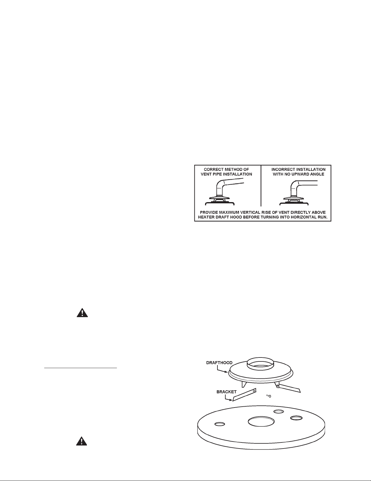
FIGURE 2
DRAFT HOOD
The draft hood furnished with this heater must be installed without
alteration. Provision must be made if it is installed in confined
space or a small room to accommodate draft hood spillage and
avoid risks described in previous steps. The upper air opening
called for in the AIR REQUIREMENTS section of this manual is for
this purpose.
Locate the 3 brackets and 6 screws in the installation instruction
bag. Secure each bracket to the draft hood leg with the screws
furnished. Place the draft hood on the water heater so that legs of
the draft hood fit into the slots on the jacket top, see figure 3. Once
the draft hood (with brackets attached) is in place, drill a small pilot
hole through bracket hole into the jacket top. WARNING, DO NOT
PENETRA TE THE JACKET TOP BY MORE THAN 1/4" (6.4 mm).
Secure the brackets to the jacket top with the screws furnished,
see Figure 3.
VENTING
WARNING
THE INSTRUCTIONS IN THIS SECTION ON VENTING MUST BE
FOLLOWED TO A VOID CHOKED COMBUSTION OR RECIRCULATION
FIGURE 3.
6
 Loading...