

WaterGroup E50TFC-3NSF, E75TFC-3NSF Installation, Operation And Service Manual

Economy Reverse Osmosis
Drinking Water System
Installation, Operation and Service Manual
#90016 8/08
Models E50TFC-3NSF and E75TFC-3NSF
are tested and certified by WQA against
NSF/ANSI 58 for the reduction of TDS.

IMPORTANT WARNING - PLEASE READ
System Flushing: This reverse osmosis system contains a preservative solution to prevent
microbiological growth and freezing which if ingested may cause irritation of the gastrointestinal tract,
colic, diarrhea or other symptoms. Therefore, approximately 5 gallons of water must be drawn from the
tap to flush out the preservative solution before using the system. This volume of water represents
approximately two days of production. The water flushed should be disposed of to the drain.
Feed Water Quality: This reverse osmosis drinking water system is not intended to be used for the
treatment of water that is microbiologically unsafe or of unknown quality. If the feed water quality is
unsafe or unknown, have a sample of the water tested by a qualified laboratory or agency and implement
the necessary measures to ensure a safe water supply.

TABLE OF CONTENTS
Introduction ............................................................................................................................................1
Models and System Configuration.........................................................................................................2
Parts List and Drawing ..........................................................................................................................3
Functional Description ...........................................................................................................................4
Your New Reverse Osmosis System (supplied items checklist) ...........................................................4
Installation Requirements ......................................................................................................................5
Installation of Feed Water Assembly ........................................................................................7
Installation of Drain Saddle Assembly ......................................................................................7
Installation of Ball Valve Assembly ...........................................................................................8
Drilling Sink Hole ......................................................................................................................8
Installation of Non-Air Gap Faucet ...........................................................................................8
Installation of Wall Mounted Airgap™.......................................................................................9
Installation of Filters ................................................................................................................10
Installation of Membrane ........................................................................................................10
Connecting Components ........................................................................................................10
Start-up Procedure...............................................................................................................................11
Maintenance Schedule ........................................................................................................................12
Sanitization Procedure for your Reverse Osmosis System ................................................................13
Maintenance Record............................................................................................................................16
Reverse Osmosis Drinking Water System Flow Diagram (all models) ...............................................17
Troubleshooting Guide.........................................................................................................................18
Warranty Information and Addresses ..................................................................................................19

1
INTRODUCTION
Congratulations, on the purchase of your new Economy Reverse Osmosis Drinking Water System. Treated with care and
regular maintenance, your new system will provide many years of service delivering purified water to the tap.
By now, you have probably already opened the box to survey the contents. Please take a few moments to review this
manual before proceeding with the installation and use of the system. Some important items to review are as follows:
• Check all components for any damage caused in shipment. Also, take a quick inventory of all items supplied
to ensure none are missing. A checklist in the next section will assist you with identifying these items.
• Ensure that the reverse osmosis system and storage tank will easily fit into the desired location. This
reverse osmosis system and tank needs to be removed for regular maintenance, so good accessibility is
an important tip to keep in mind.
• Read all warnings contained within this manual.
Although this product is described as a ‘Drinking Water System’, the purified water produced by the reverse osmosis (RO)
process can be used for many purposes around the home.
• Drinking Water - keep container of RO water in the fridge to be able to enjoy the clean, fresh taste.
Alternatively, take it directly from the tap.
• Ice Cubes - use RO water to fill ice cube trays. Ice cubes made from RO water are typically
clearer and better tasting than ice made from plain tap water.
• Automatic Ice Makers - a water line from the RO system can be plumbed to refrigerators with automatic
icemakers. Additional accessories required to complete this connection are not included. Please consult the
refrigerator’s owner’s manual on this installation.
• Kettles and Coffee Makers - plain tap water eventually causes films and scale in these devices that is
difficult to clean. RO water is very low in dissolved minerals content, greatly reducing the chance of scale
buildup.
• Cooking - use RO water for boiling pasta, rice or any other recipe that calls for water in the instructions.
• Washing Fresh Fruit & Vegetables - prevent tap water minerals from being deposited onto food to
maintain freshness.
• Family Pets - Allow your dog or cat to enjoy the same purified water you do.
• Irons and Steamers - prevent mineral buildup in household appliances that use water and eventually build
up with scale when using plain tap water.
Now you can relax and enjoy the benefits of great tasting water supplied by your reverse osmosis drinking water system.
Remember that good quality water is important to maintaining a healthy lifestyle. You can also feel good about the money
you have saved by installing your own drinking water system instead of dealing with the expense and hassle of bottled
water delivery.
2
Certified Contaminant Reduction Performance
The following Economy Reverse Osmosis Systems conform to NSF/ANSI 58 for the specific performance claims as verfied and substantiated by
test data.
NOTES:
1. TFC refers to reverse osmosis membranes constructed from a THIN FILM COMPOSITE
2. The daily production rate is the volume of product water produced by the system per day and is determined by testing in accordance with the procedure outlined in NSF/ANSI Standard 58.
3. System’s Efficiency rating as verified by testing in accordance with NSF/ANSI standard 58. Efficiency rating means the percentage of the influent water to the system that is available
to the user as reverse osmosis treated water under operating conditions that approximate typical daily usage.
4. System’s Recovery rating as verified by testing in accordance with NSF/ANSI Standard 58. System’s Recovery rating means the percentage of the influent water to the membrane
portion of the system that is available to the user as reverse osmosis treated water when the system is operated without a storage tank or when the storage tank is bypassed.
5. PRESSURE REGULATOR IS RECOMMENDED FOR FEED WATER PRESSURES EXCEEDING 552 kPa (80 psig)
Models & System Configurations
Conditions for Use
Item Model Storage # of Storage Tank Vessel Vessel Vessel Vessel Daily Production Efficiency Recovery
Number Description Tank Vessels Capacity Litres (gal) 1 2 3 4 Rate
(2)
L/day (G/day) Rating
(3)
% Rating
(4)
%
2885 RO,E50TFC-3NSF Plastic 4 6 (1.6) Sediment Filter Carbon Filter TFC
(1)
Membrane Carbon Filter 45.4 (12) 8.5 17.5
2886 RO,E75TFC-3NSF Plastic 4 8.7 (2.3) Sediment Filter Carbon Filter TFC
(1)
Membrane Carbon Filter 100 (26.4) 14.5 25.8
2887 RO,E50TFC-3NSF Metal 4 8.3 (2.2) Sediment Filter Carbon Filter TFC
(1)
Membrane Carbon Filter 45.4 (12) 8.5 17.5
2888 RO,E75TFC-3NSF Metal 4 8.7 (2.3) Sediment Filter Carbon Filter TFC
(1)
Membrane Carbon Filter 100 (26.4) 14.5 25.8
Source Water Supply Profile
Chemical Parameters
Max mg/L
Community/Private Chlorinated/Non-Chlorinated Hardness (CaCO
3
) <350 (< 20 gpg)
Feed Water Pressure
(5)
242 – 690 kPa (35 – 100 psig) Iron (Fe) <0.1
Temperature 4° – 38°C (40° – 100°F) Manganese (Mn) <0.05
pH Range 3.0 – 11.0 Hydrogen Sulfide (H2S) 0.00
Maximum TDS Level 2000 mg/L Residual Chlorine (Cl2) <2.0
Turbidity** <1.0 NTU **Nephelometric Turbidity Unit
Maximum SDI*** <4.0 ***Silt Density Index: Value stated in SDI units.
Models E50TFC-3NSF and E75TFC-3NSF
are tested and certified by WQA against
NSF/ANSI 58 for the reduction of TDS.
3
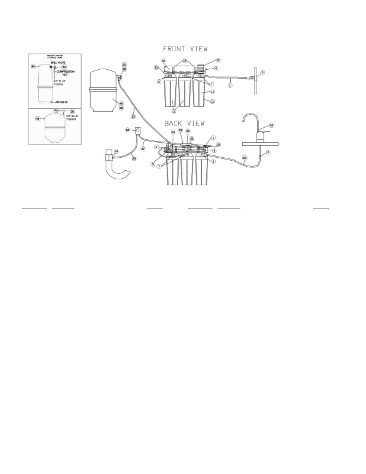
Drawing No.
Description Item No.
1.......... Tubing, 1/4" OD, poly, natural 92600
2A......... Valve, 3/8", Shut Off 80704
2B......... Ball valve, 3/8" 33503601
3.......... Connector, faucet, 3/8", QC 92601
4A......... Tank, storage, RO, 3800, white, c/w shut off 92313
4B......... Tank, storage, RO, 4.0 gal., metal 42600029
5.......... Valve, inlet, saddle, self-priming, 3/8"-1/2" pipe 92276
6.......... Elbow, 1/4" QC x 1/8" mnpt 92603
7.......... Elbow, 1/4" QC x 1/4" mnpt 92604
8.......... Elbow, 3/8" QC x 1/4” mnpt 92605
9.......... Tee, 3/8", QC 92606
10......... Membrane, RO
50 GPD, TFC 92607
75 GPD, TFC 92608
11......... Housing, cartridge, white/black 92026
12......... Cartridge, pre-filter, 5 micron 26091
13......... Cartridge, carbon 26081
14......... Saddle, drain, set, RO, 3/8" 92160
15......... Clip, pipe, 2", set 92162
16......... Faucet, standard 92609
17......... Vessel, membrane 92211
18......... Valve, shut-off, auto 92223
19......... Control, flow
300 ml/min, RO 50 GPD 92610
400 ml/min, RO 75 GPD 92611
20......... Valve, check, product water 92612
21......... Bracket, RO, 3 housing 92279
22......... Bracket, Shut Off, Auto 92224
23......... Tubing, 3/8" OD, poly, natural 92613
24......... Reducer 1/4" x 3/8" Stem x QC 92614
25......... Tubing, 3/8" OD, poly, blue 92615
26......... Tubing, 3/8" OD, poly, red 87604
27......... Tubing, 1/4" OD, poly, red 115201
28......... Airgap, RO, Remote, Plastic 44403001
Drawing No.
Description Item No.
Membranes and Filters
10......... Reverse Osmosis TFC Membrane
50 GPD, TFC 92607
75 GPD, TFC 92608
12......... Cartridge, pre-filter, 5 micron 26091
13......... Cartridge, carbon (2 each) 26081
Flow Control
19......... Control, Flow, 300ml, RO 50 GPD 92610
19......... Control, Flow, 400 ml, RO 75 GPD 92611
Product Water Faucet
16......... Faucet, Standard 92609
Product Water Tank*
4A......... Tank, Storage, Plastic 92313
4B......... Tank, Storage, Metal 42600029
Installation Kit
Complete Kit – – –
14......... Saddle, Drain, 3/8" 92160
5.......... Valve, Inlet, Saddle, Self Piercing, 3/8"-1/2" Pipe 92276
3.......... Connector, Faucet, 3/8", QC 92601
1.......... Tubing, 1/4" OD, poly, natural 92600
23......... Tubing, 3/8" OD, poly, natural 92613
24......... Reducer, 1/4" x 3/8" Stem x QC 92614
25......... Tubing, 3/8" OD, poly, blue 92615
26......... Tubing, 3/8" OD, poly, red 87604
27......... Tubing, 1/4" OD, poly, red 115201
28......... Airgap, RO, Remote Plastic 44403001
Owners Guide 90016
Performance Sheet 90019
* Replacement parts can be obtained from your local dealer. Refer to your local
dealer stamp at the back page of this performance data sheet.
Parts List and Drawing - Models E(50 & 75) TFC-3NSF
Note: There may be some parts listed, which are not included with this model.
Component and Interconnection Locators*
4
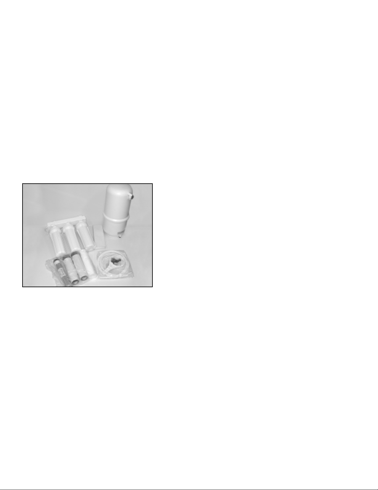
Supplied Item Checklist
Out of the box, your new R.O. System should be supplied with the following items. If any items appear to be missing,
please contact the distributor who sold the system.
1. Pressure tank & right angle shut-off valve with compression nut
2. Reverse Osmosis System
3. Reverse Osmosis membrane element, 5 micron pre-filter, precarbon filter, carbon filter (in individual sealed protective bags)
4. Filter sump wrench, drain line saddle assembly, tubing bundle,
feed water saddle piercing valve, quick connect fitting; 3/8" tube x
1/8" FNPT
5. Faucet assembly
6. Airgap™ Kit
Figure 1 - Supplied items for 3 sump models
Functional Description
Feed water enters the 5-micron pre-filter, which filters out suspended particles such as dirt or sediment. The filtered water
then enters the pre-carbon filter (3 sump models only), which contains granular activated carbon, which removes any
chlorine from the water.
The water then enters the reverse osmosis membrane. The membrane will allow only permeate (product water) to pass
through. The brine (waste water) goes to the drain.
Permeate then flows through a hydraulic shut-off valve to the storage tank. When the tank fills and the tank pressure
reaches approximately 2/3 of the inlet feed water pressure, the shut-off valve closes, which turns the system off.
When water is drawn from the faucet, permeate flows from the storage tank through the post carbon filter. This filter
contains granulated activated carbon, removing any taste and odor that has accumulated while stored in the tank. When
the tank empties, the shut-off valve opens, turning the unit on.

5
Installation Requirements
READ THIS ENTIRE INSTALLATION AND SERVICE GUIDE BEFORE BEGINNING INSTALLATION.
The Economy Reverse Osmosis (RO) Drinking Water Treatment Systems have been designed for ease of installation and
serviceability and are constructed with the finest materials available. Using these instructions and paying close attention
to the parameters outlined within "CONDITIONS FOR USE" detailed on Page 2 will ensure a successful installation.
To ensure a system continues to operate at its optimum level, it is necessary to have a routine maintenance and
replacement schedule (page 16). Frequency at which filters must be changed will depend on quality of feed water supply
and level of system usage.
These RO systems contain a replaceable treatment component critical to the efficiency of the system.
Replacement of the reverse osmosis component should be with one of identical specification, as defined by
WaterGroup to assure the same efficiency. Product water shall be tested periodically to verify the system is
performing properly.
DO NOT USE WITH WATER THAT IS MICROBIOLOGICALLY UNSAFE OR OF UNKNOWN QUALITY
WITHOUT ADEQUATE DISINFECTION BEFORE OR AFTER THE SYSTEM.
All State/Provincial and local government codes regarding installation of these devices must be observed.
Verify Water Supply is Potable
The water supply must meet provincial/state and/or national standards for potable drinking water. Water samples should
be sent to a certified laboratory for analysis.
Placement of Components
Placement of the various components of the system will vary from installation to installation. The main objective is to place
the components so that they are accessible for servicing and ease of installation.
Do not place module where it will be exposed to freezing and/or direct sunlight.
Spigot
Proper faucet placement should ensure a no-splash waterfall pattern into the sink. The spigot handle should be positioned
to either the left or right as one faces the sink.
Storage Tank
The storage tank should be placed so that it can be easily removed from under the sink. Avoid placing the storage tank
in out-of-the-way cabinets or dead spaces. There are two reasons for this: 1) the difficulty of installation increases
significantly and 2) when the storage tank is located further away from the faucet, the flow rate diminishes.
Module Assembly
The module assembly should be hung on a sink cabinet side-wall with the two wood screws.
Quick Connect Fittings
All connections are quick connect fittings except for the compression fitting at the inlet sadle valve, drain saddle valve and
storage tank shutoff valve.
 Loading...