

WaterGroup Aqua Flo Installation, Operation And Instruction Manual
Reverse Osmosis
Drinking Water System
Installation, Operation and Service Manual


IMPORTANT WARNING - PLEASE READ
System Flushing: This reverse osmosis system contains a preservative solution to prevent
microbiological growth and freezing which if ingested may cause irritation of the
gastrointestinal tract, colic, diarrhea or other symptoms. Therefore, approximately 5
gallons of water must be drawn from the tap to flush out the preservative solution before
using the system. This volume of water represents approximately two days of production.
The water flushed should be disposed of to the drain.
Feed Water Quality: This reverse osmosis drinking water system is not intended to be
used for the treatment of water that is microbiologically unsafe or of unknown quality. If
the feed water quality is unsafe or unknown, have a sample of the water tested by a
qualified laboratory or agency and implement the necessary measures to ensure a safe
water supply.

TABLE OF CONTENTS
Introduction ............................................................................................................................................1
Product Specifications & Application Guidelines ...................................................................................2
Functional Description ...........................................................................................................................2
Your New Reverse Osmosis System (supplied items checklist) ...........................................................3
Installation..............................................................................................................................................4
Startup and Operation............................................................................................................................9
Maintenance ........................................................................................................................................10
Sanitization Procedures .......................................................................................................................11
Maintenance Schedule ........................................................................................................................14
Part List and Drawing for D75TFC-3 ...................................................................................................15
Parts List and Drawing for E75TFC-3 / E50TFC-3 / E24TFC-3..........................................................16
Parts List and Drawing for E50TFC-2SF .............................................................................................17
Reverse Osmosis Drinking Water System Flow Diagram (all models) ...............................................18
Troubleshooting Guide.........................................................................................................................19
Warranty Information & Addresses......................................................................................................20

1
INTRODUCTION
Congratulations, on the purchase of your new Reverse Osmosis Drinking Water System. Treated with care
and regular maintenance, your new system will provide many years of service delivering purified water to
the tap.
By now, you have probably already opened the box to survey the contents. Please take a few moments to
review this manual before proceeding with the installation and use of the system. Some important items
to review are as follows:
• Check all components for any damage caused in shipment. Also, take a quick inventory of
all items supplied to ensure none are missing. A checklist in the next section will assist you
with identifying these items.
• Ensure that the reverse osmosis system and storage tank will easily fit into
the desired location. This reverse osmosis system and tank needs to be removed for
regular maintenance, so good accessibility is an important tip to keep in mind.
• Read all warnings contained within this manual.
Although this product is described as a ‘Drinking Water System’, the purified water produced by the
reverse osmosis (RO) process can be used for many purposes around the home.
• Drinking Water - keep container of RO water in the fridge to be able to enjoy the clean,
fresh taste. Alternatively, take it directly from the tap.
• Ice Cubes - use RO water to fill ice cube trays. Ice cubes made from RO water are typically
clearer and better tasting than ice made from plain tap water.
• Automatic Ice Makers - a water line from the RO system can be plumbed to refrigerators
with automatic icemakers. Additional accessories required to complete this connection are
not included. Please consult the refrigerator’s owner’s manual on this installation.
• Kettles and Coffee Makers - plain tap water eventually causes films and scale in these
devices that is difficult to clean. RO water is very low in dissolved minerals content, greatly
reducing the chance of scale buildup.
• Cooking - use RO water for boiling pasta, rice or any other recipe that calls for water in
the instructions.
• Washing Fresh Fruit & Vegetables - prevent tap water minerals from being deposited
onto food to maintain freshness.
• Family Pets - Allow you dog or cat to enjoy the same purified water you do.
• Irons, Steamers & Humidifiers - prevent mineral buildup in household appliances that use
water and eventually build up with scale when using plain tap water.
Now you can relax and enjoy the benefits of great tasting water supplied by your reverse osmosis drinking
water system. Remember that good quality water is important to maintaining a healthy lifestyle. You can
also feel good about the money you have saved by installing your own drinking water system instead of
dealing with the expense and hassle of bottled water delivery.
2
Application Guidelines
(1)
Nominal product water ratings are based on the following conditions: Supply TDS of 250 ppm softened tap water, 50 psi (0.36 Mpa), 77oF (25oC), pH
8 and 15% recovery with outlet to atmosphere.
(2)
Rejection percentages are dependent on the supply conditions and the substance being measured.
Notes:
The performance of a reverse osmosis membrane is highly dependent upon pressure, temperature and TDS. The actual volume of product
water and rejection percentage will vary with differences from the test conditions that membrane ratings are based upon.
These drinking water systems are not intended to be used for the treatment of water that is microbiologically unsafe or of unknown quality..
Functional Description
Feed water enters the 5-micron pre-filter (combination 5 micron/carbon filter in 2 sump models), which
filters out suspended particles such as dirt or sediment. The filtered water then enters the pre-carbon filter
( in 3 sump models only), which contains granular activated carbon, which removes any chlorine from the
water. The two sump models utilize a combination 5-micron/carbon filter to filter fine particles and remove
chlorine.
Model D75TFC-3 only: Water from the pre-carbon filter enters the scale inhibitor filter. This filter inhibits
the formation of scaling deposits on the surface of the membrane, providing better protection and longer
membrane life.
The water then enters the reverse osmosis membrane. The membrane will allow only permeate (pure
water) to pass through. The brine (waste water) goes to the drain.
Permeate then flows through a hydraulic shut-off valve to the storage tank. When the tank fills and the tank
pressure reaches 2/3 of the inlet feed water pressure, the shut-off valve closes, which turns the system
off.
When water is drawn from the faucet, permeate flows from the storage tank through the post carbon
filter. This filter contains granulated activated carbon, removing any taste and odor that has accumulated
while stored in the tank. When the tank empties, the shut-off valve opens, turning the unit on.
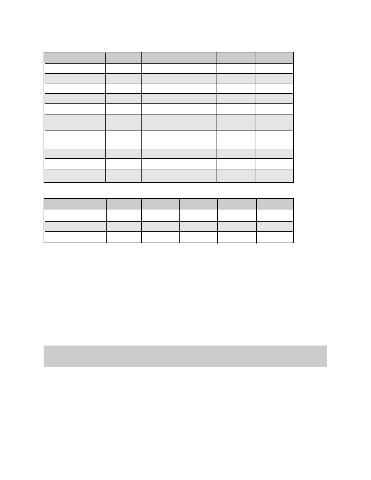
Model Number D75TFC-3 E75TFC-3 E50TFC-3 E24TFC-3 E50TFC-2SF
Membrane Type TFC TFC TFC TFC TFC
Max. Feed Water Salinity 2000 ppm 2000 ppm 2000 ppm 2000 ppm 2000 ppm
Feed Water Temperature 40-110°F 40-110°F 40-110°F 40-110°F 40-110°F
Feed Water Pressure 50-100 psi 50-100 psi 50-100 psi 50-100 psi 50-100 psi
Feed Water pH 2.0-11.0 2.0-11.0 2.0-11.0 2.0-11.0 2.0-11.0
Feed Water Supply Chlorinated Chlorinated Chlorinated Chlorinated Chlorinated
Unchlorinated Unchlorinated Unchlorinated Unchlorinated Unchlorinated
Feed Water Hydrogen
Sulphide
None None None None None
Feed Water Manganese <0.05 ppm <0.05 ppm <0.05 ppm <0.05 ppm <0.05 ppm
Feed Water Iron <0.1 ppm <0.1 ppm <0.1 ppm <0.1 ppm <0.1 ppm
Feed Water Hardness <10 gpg <10 gpg <10 gpg <10 gpg <10 gpg
Specifications
Model Number D75TFC-3 E75TFC-3 E50TFC-3 E24TFC-3 E50TFC-2SF
Membrane Production Rate
(1)
75 USGPD 75 USGPD 50 USGPD 24 USGPD 50 USGPD
Rejection
(1)
up to 99% up to 99% up to 99% up to 99% up to 99%
Storage Tank Capacity US Gal
4.0 4.0 4.0 4.0 4.0
3
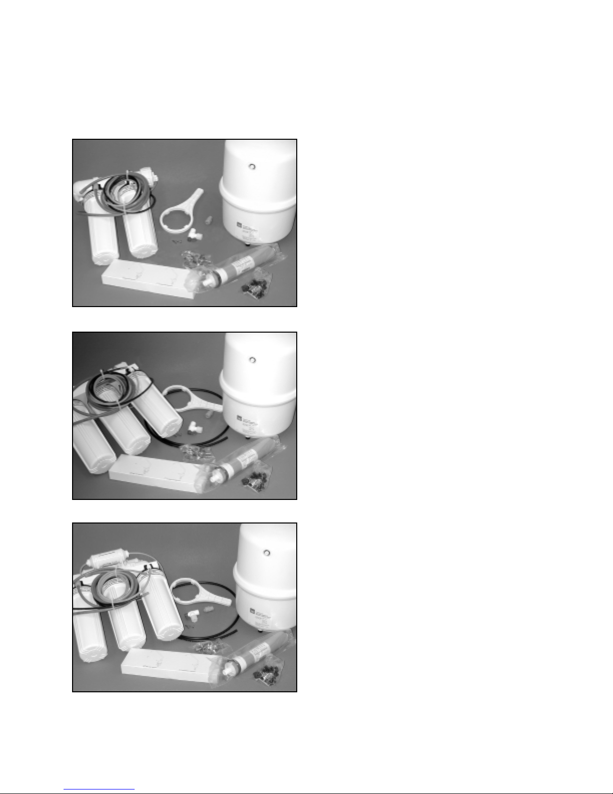
Supplied Item Checklist
Out of the box, your new R.O. System should be supplied with the following items. If any items appear to
be missing, please contact the distributor who sold the system.
1. Pressure Tank
2. Reverse Osmosis System, complete with
tubing bundle
3. Reverse Osmosis membrane element (in
sealed protective bag)
4. Filter Sump Wrench
5. Length of black tubing
6. Drain line saddle assembly
7. Feed Water saddle valve assembly
8. Mounting screws, two (2)
9. Quick connect fitting; 3/8” tube x 1/8” FNPT
10. Faucet assembly
11. Right angle shut off valve with compression
nut
Figure 1 - Supplied items for 2 sump models
Figure 2 - Supplied items for 3 sump models
Figure 3 - Supplied items for 3 sump “D” models
4
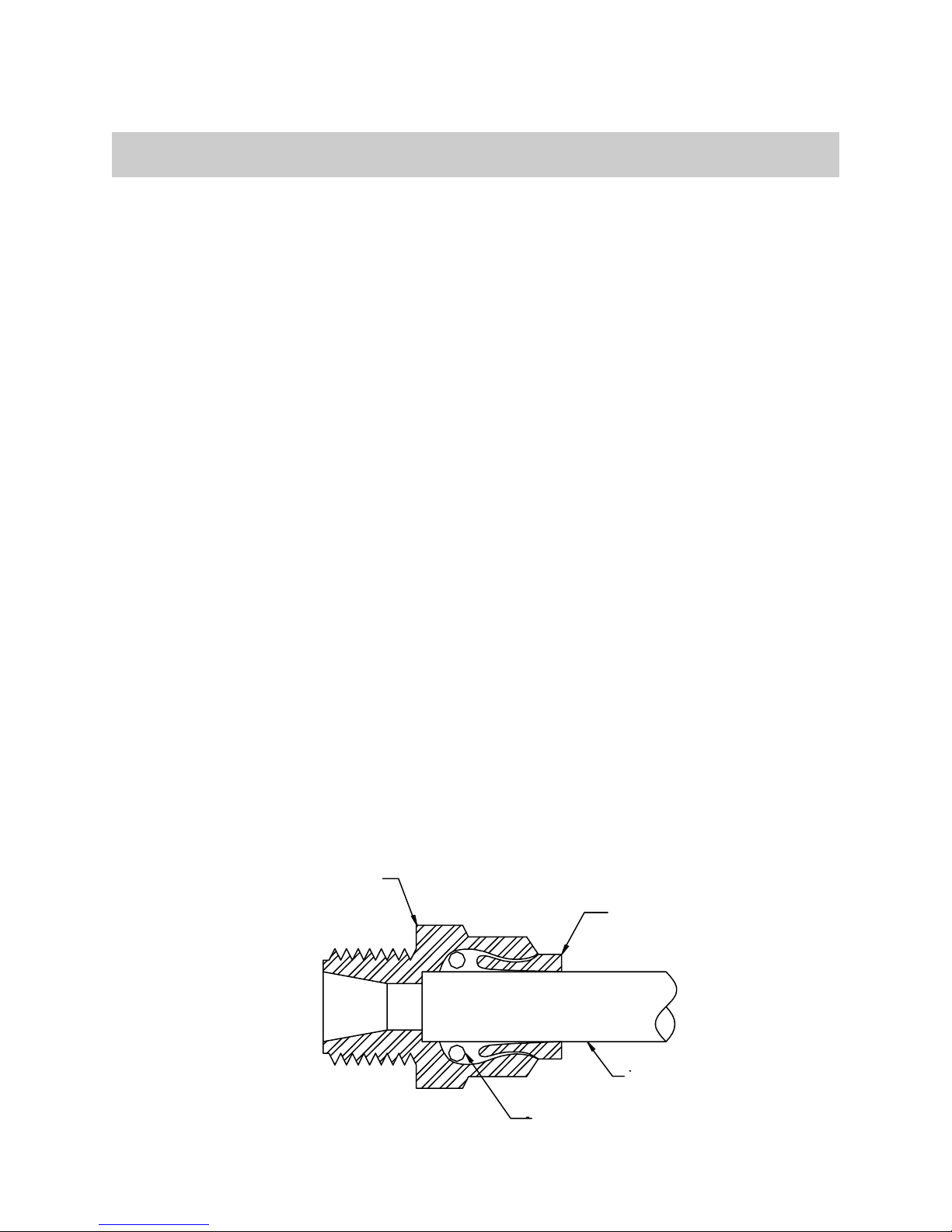
Collet
Body
Tube
O-Ring
Installation
All State/Provincial and local government codes regarding installation of these devices must be
observed.
Verify Water Supply is Potable
The water supply must meet provincial/state and/or national standards for potable drinking water. Water
samples should be sent to a certified laboratory for analysis.
Placement of Components
Placement of the various components of the system will vary from installation to installation. The main
objective is to place the components so that they are accessible for servicing and ease of installation.
Spigot
Proper spigot placement should ensure a no-splash waterfall pattern into the sink. The spigot handle
should be positioned to either the left or right as one faces the sink.
Storage Tank
The storage tank should be placed so that it can be easily removed from under the sink. Avoid placing
the storage tank in out-of-the-way cabinets or dead spaces. There are two reasons for this: 1) the
difficulty of installation increases significantly and 2) when the storage tank is located further away from
the spigot, the flow rate diminishes.
Module Assembly
The module assembly should be hung on a sink cabinet side-wall with the two wood screws provided.
Quick Connect Fittings
All connections are quick connect fittings except for the two slip-on barbed tubing connections on the air
gap spigot (optional).
To Prepare Tubing
•
Cut the tube squarely and remove any burrs.
•
Mark from the end of the tube the length of insertion. (1/4" O.D. - 11/16", 3/8" O.D. - 3/4")
To Insert Tubing into Fitting
•
Insert tube straight into fitting until it bottoms out on interior shoulder and insertion mark is no longer
visible.
To Release Tubing
•
Push collet toward body and pull on tubing to release tube. To re-use fitting, begin assembly over
again.
Figure 4 - Quick Connect Fitting
 Loading...