

WaterGroup 4VTFC09G-PB, 4VTFC25G-PB, 4VTFC50G-PB, 4VTFC75G-PB Owner's Manual
OWNER’S GUIDE
ADVANCED REVERSE OSMOSIS
WATER TREATMENT SYSTEMS
WQA Tested and Certified against
CSA B483.1:
4VTFC09G-PB 4VTFC50G-PB
4VTFC25G-PB 4VTFC75G-PB
These models are tested and certified by
WQA against NSF/ANSI 58 for the
reduction of TDS. Tested and Certified by
WQA against ORD0902 for “lead free”
compliance.
4VTFC09G-PB 4VTFC50G-PB
4VTFC25G-PB 4VTFC75G-PB

Please fill in the following information and retain for reference:
Unit Model Number: _________________________________
Serial Number: _____________________________________
Date Purchased: ____________________________________
Date Installed: ______________________________________

I
INTRODUCTION
Congratu lations, on the purc hase of your new Advanced Reverse Osmosis Water Treatment System. Treated with care and
regu lar maintenance, your new system will provide many years of service deliv er ing great tasting water to the tap .
By now, you have probably a lready opened the box to survey the contents. Please take a few moments to review this
manual before proceeding with the installation an d use of the system. So me important ite ms to review are as follows:
o Check all components for any da mage caused in shipment. Also, take a qu i ck inventory of all items suppl ied
to ensure none are missing. A che cklist in the next section wi l l assist you with ide ntifying these items.
o Ensure that the reverse osmosis system and storage tank wil l easily fit into th e desired lo cation. Th is reverse
osmosis system and tank needs to be re moved for regular ma intenanc e, so good a c cessibi l ity is an i mportant
tip to keep in mind.
o Read all CAUTIONS and NOTES c ontained within this manual. They prov ide valua b l e installation tips and
advice on how to properly install and maintain your Reverse Osmosis Drinking Water System.
o For installation in Massachusetts, the Massachusetts Plumbing Code 248 CMR shall be adhered to.
Consult your licensed plumber for installation of this system. The use of saddle (piercing) valves is not
permitted.
The water produced by the reverse osmosis (RO) process can b e used for many purposes arou nd the home.
o Drinking Water - keep a container of RO water in th e fridge to be able to enjoy the c leaner, fresher taste.
Alternat ive ly, take it directly from the tap.
o Ice Cubes - use RO water to fill ice cube trays. Ice cubes made from RO water are typ ically c learer and
better tasting than i c e made from tap water.
o Automatic Ice Makers - a water line from th e RO system can be plumb ed to refrigerators with automati c
icemakers. Addit ional ac cessories required to co mp lete this connection are no t inc l u ded. Please c onsult
the refrig erator’s owner’s manual on this installat ion.
o Kettles and Coffee Makers - tap water eventual ly causes fil ms and scale in these dev i c es that is d iffic u lt
to c lean. RO water is very low in d issolved minerals c ontent, greatly reducing the cha n c e of scale
buildup.
o Cooking - use RO water for boiling pasta, rice or any other re c ipe that calls for water.
o Washing Fresh Fruit & Vegetables - prevent tap water m inerals from being de posited onto food to
ma i ntain freshness.
o Family Pets – A l l ow your pets to enjoy the same gre at tasting water you do.
o Irons & Steamers - preve nt minera l bu i ldup in h ousehold applianc es that use water and eventually bui l d
up with scale when using tap water.
Now you can enjoy all the benefits of great tasting water supplied by your reverse osmosis drinkin g water system.
II
CERTIFIED CONTAMINANT REDUCTION PERFORMANCE
The following 12403 Series Reverse Osmosis Systems conform to NSF/ANSI 58 for the specific performance claims as verified and substantiated
by test data.
MODELS AND SYSTEM CONFIGURATIONS
Table 1
Model
Description
Storage
Tank
# of
Vessels
Storage
Tank
Capacity
Litres (gal)
Vessel
1
Vessel 2 Vessel
3
Vessel
4
Daily
Production
Rate
(2)
L/day
(G/day)
Efficiency
Rating
(3)
%
Recovery
Rating
(4)
%
Monitor
(6)
4VTFC09G-PB
Plastic/Metal
4
6.81 (1.8)
Sediment
Filter
Carbon
Filter
TFC
(1)
Membrane
Carbon
Filter
15.5 (4.1)
12.8
35
4VTFC25G-PB
Plastic/Metal
4
7.19 (1.9)
Sediment
Filter
Carbon
Filter
TFC
(1)
Membrane
Carbon
Filter
29.1 (7.7)
8.2
18
4VTFC50G-PB
Plastic/Metal
4
6.81 (1.8)
Sediment
Filter
Carbon
Filter
TFC
(1)
Membrane
Carbon
Filter
34.44 (9.1)
4.8
16.7
4VTFC75G-PB
Plastic/Metal
4
7.19 (1.9)
Sediment
Filter
Carbon
Filter
TFC
(1)
Membrane
Carbon
Filter
49.58 (13.1)
5.7
15.3
Smartap®
Push
Button
CONDITIONS FOR USE
Table 2
Source Water Supply Profile
Chemical Parameters
Max mg/L
Community/Private
Chlorinated/Non-Chlorinated
Hardness (CaCO3 )
<170 (10 gpg)
Feed Water Pressure
(5)
242-690 kPa (35-100 psig)
Iron (Fe )
<0.1
Temperature
4°-38° C (40°-100° F)
Manganese (Mn)
<0.05
pH Range
3.0 - 11.0
Hydrogen Sulfide (H2S )
0.00
Maximum TDS Level
2000 mg/L
Residual Chlorine (Cl2)
<2.0
Turbidity**
<1.0 NTU
Maximum SDI*** <4.0
** Nephelometric Turbidity Unit
*** Silt Density Index: Value stated in SDI units.
NOTES:
1. TFC refers to reverse osmosis membranes constructed from a THIN FILM COMPOSITE
2. The daily production rate is the volume of product water produced by the system per day and is determined by testing in accordance with the procedure
outlined in NSF/ANSI Standard 58.
3. System’s Efficiency rating as verified by testing in accordance with NSF/ANSI standard 58. Efficiency rating means the percentage of the influent water to
the system that is available to the user as reverse osmosis treated water under operating conditions that approximate typical daily usage.
4. System’s Recovery rating as verified by testing in accordance with NSF/ANSI Standard 58. System’s Recovery rating means the percentage of the
influent water to the membrane portion of the system that is available to the user as reverse osmosis treated water when the system is operated without a
storage tank or when the storage tank is bypassed.
5. PRESSURE REGULATOR IS RECOMMENDED FOR FEED WATER PRESSURES EXCEEDING 552 kPa (80 psig)
6. SMARTAP® PUSH BUTTON MONITOR. Indicator lights located on the module cover report system status.
OPTIONS AND ACCESSORIES
PRODUCT WATER FAUCETS
BOOSTER PUMP
Faucets will be supplied as Air Gap.
A booster pump may be used if system pressure is below 242 kPa (35 psi).
Pump should be placed near RO Module and installed in feed water line just
before it enters Module.
Models 4VTFC09G-PB, 4VTFC25G-PB, 4VTFC50G-PB
and 4VTFC75G-PB are tested and certified by WQA
against NSF/ANSI 58 for the reduction of TDS.
Tested and Certified by WQA against ORD0902 for
“lead free” compliance.
WQA Tested and
Certified against
CSA B483.1
III
GENERAL INFORMATION
This Owner’s Guide covers all components that may be included with a system. Information relating to any component that is NOT included with
your system may be disregarded.
SYSTEMS WITH AIR GAP FAUCET, MODEL 12403
n/s - not shown
REVERSE OSMOSIS SYSTEM
Item
Description
Part No.
1
4 Vessel Module, With Quality Monitor
Fig 8
MEMBRANE AND FILTERS
2
3
4
5
Reverse Osmosis TFC Membrane
9 GPD, Yellow Casing, Red Tape
25 GPD, Yellow Casing, Black Tape
50 GPD, Yellow Casing, White Tape
75 GPD, Yellow Casing, Blue Tape
Sediment Filter
Carbon Pre-Filter
Carbon Post Filter
33001071
33001068
33001033
33001056
41400008
41400009
41400009
FLOW RESTRICTOR TUBING
6
Flow Restrictor Tubing
9 GPD
25 GPD
50 GPD
75 GPD
40600034
40600040
40600041
40600042
PRODUCT WATER FAUCETS
Item
Description
Part No.
7 8 Chrome-Plated Metal, Air Gap
Connector, Faucet 3/8” x 7/16”
92192, Fig 7
92407
INSTALLATION KIT
9
10
11
12
13
14
n/s
n/s
n/s
Complete Kit
Supply Valve, Saddle-Tapping
Drain Clamp, Saddle Clamp, Air Gap, 3/8”
Tubing, 3/8”, Red
Tubing, 3/8”, Blue
Tubing, 3/8”, White
Tubing, 1/4", White
Screw, Mounting Bracket (2 each)
Elbow, Stem, 3/8” (2 each)
Elbow, Stem ¼” (2 each)
92276
92160
87604
87600
115207
115200
32701006
33501071
33501064
n/s
n/s
n/s
n/s
Owner’s Guide
Kit, O-Rings, Collets, QC ¼” & 3/8”
Safety Clip 1/4”
Safety Clip 3/8”
36101291
92166
96345
92346
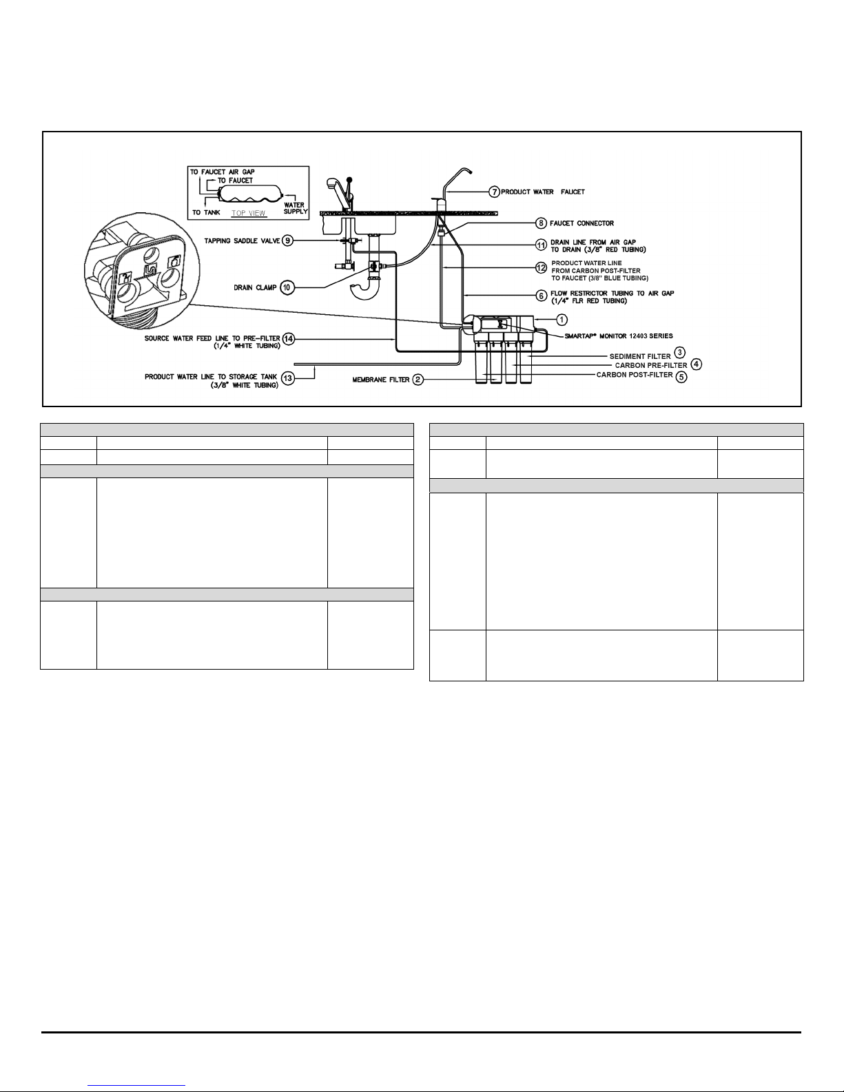
Figure 1.A: Component* and Interconnection Locators, Model 12403.
*Replacement parts can be obtained from your local dealer. Refer to your local dealer stamp at the back page of this manual.
IV
GENERAL INFORMATION
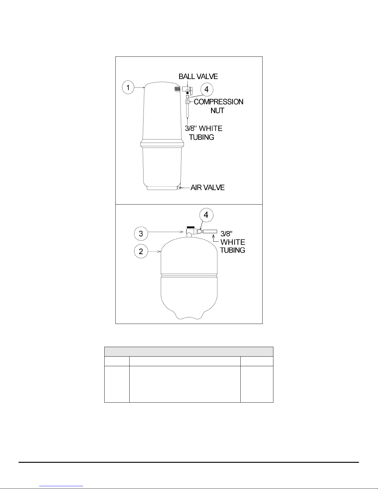
PRODUCT WATER STORAGE TANKS
PRODUCT WATER STORAGE TANKS - ALL SYSTEMS
Item
Description
Part No.
1
2
3
4
Storage Tank Assembly, Polymer
Storage Tank Assembly, Metal
Ball Valve, 3/8”, Steel Tank
Ball Valve, 3/8”, Plastic Tank
Insert, 3/8”
92313
92342/92294
33503601
80704
92329
Figure 1.B: Product Water Storage Tanks.
 Loading...