

Waterford JSAL210F, JSAL210E, JSAL210D, JSAL180F, JSAL180E Owner's Manual
...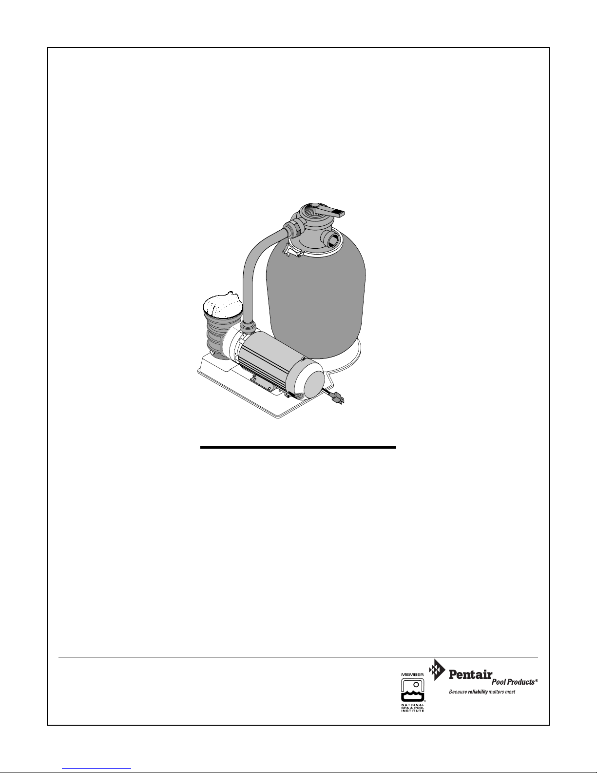
WATERFORD SYSTEMS
HIGH RATE SAND FILTER SYSTEM
For Above Ground Swimming Pools
O W N E R ’ S M A N U A L
INSTALLATION, OPERATION & PARTS
Sta-Rite Pool/Spa Group
293 Wright Street, Delavan, WI 53115
International: 262-728-5551, FAX: 262-728-7550
www.starite.com
Union City, TN • Delavan, WI • Mississauga, ON
© 2006,Sta-Rite Industries
S260 (Rev. 4/26/06)
839 0494
Models
15" Tank 18" Tank 21" Tank
3/4 HP JSAL15D JSAL180D JSAL210D
1 HP JSAL15E JSAL180E JSAL210E
1 HP (2-Speed) JSAL180E JSAL210E
1-1/2 HP JSAL180F JSAL210F
This manual should be furnished to the end user
of this system; its use will reduce service calls and
chance of injury and will lengthen system life.
oducts,
entair P
P
1620 Ha
Sanf
Tel 919-774-4151 • Fax 919-774-4841
ool Pr
wkins Ave.
ord, NC 27330
Inc.
B 6/28/06)
.
S260 (Re
v
2
HIGH-RATE SAND FILTER SYSTEM
To avoid unneeded service calls, prevent possible injuries, and get the most out
of your filter, READ THIS MANUAL CAREFULLY!
The High Rate Sand Filter System:
• Is designed to circulate and filter water in above ground swimming pools.
• Offers quiet, efficient performance and is durable, reliable.
• With a 3’ cord or no cord, use with permanently installed pools ONLY
(see CAUTION #7, below).
• With a 25’ cord, use with storable pools ONLY (see CAUTION #8, below).
Table of Contents
Safety Instructions.......................................................................................................3
Specifications/Dimensional Data...............................................................................4
General Information..................................................................................................5
Installation.............................................................................................................5-7
Filter Mount/Piping ................................................................................................5
Filter Set-up ...........................................................................................................6
Loading Sand Media ..............................................................................................6
Valve Installation................................................................................................6-7
Electrical ..................................................................................................................7
Startup/Operation/Backwash..................................................................................8-9
Maintenance.............................................................................................................9
Storage/Winterizing ................................................................................................10
Multi-Port Valve Service .........................................................................................11
Valve Removal .......................................................................................................11
Pump Service ....................................................................................................11-12
Troubleshooting Guide ...........................................................................................13
Repair Parts List .................................................................................................14-17
Warranty ................................................................................................................18
IMPORTANT SAFETY INSTRUCTIONS
When installing and using electrical equipment, basic safety precautions should always be followed,
including the following:
SAVE THESE INSTRUCTIONS
1. READ AND FOLLOW ALL SAFETY INSTRUCTIONS.
2. To reduce the risk of injury, do not permit
children to use this product unless they are closely supervised at all times.
3. Risk of electrical shock. Connect only to a
grounding type receptacle protected by a ground-fault circuit-interrupter(GFCI). Contact a qualified electrician if you
cannot verify that the receptacle is protected by a GFCI.
4. Do not bury cord. Locate cord to minimize abuse from
lawn mowers, hedge trimmers, and other equipment.
5. To reduce the risk of electrical shock,
replace a damaged cord immediately.
6.
To reduce the risk of electrical shock, do
not use an extension cord to connect unit to electrical supply; provide a properly located outlet.
7. Permanent pumps are for use with permanently installed pools and may also be used with hot tubs
and spas if so marked. Do not use with storable pools. A
permanently installed pool is constructed in or on the
ground or in a building such that it cannot be readily disassembled for storage. A storable pool is constructed so that
it may bereadily disassembled for storage and reassembled
to its original integrity.
8. Storable pool pumps are for use with
storable pools only. Do not use with permanently installed
pools. A storable pool is constructed so that it is capable
of being readily disassembled for storage and reassembled
to its original integrity. A permanently installed pool is
constructed in or on the ground, or in a building, such that
it cannot be readily disassembled for storage.
3
This is the safety-alert symbol. When you see
this symbol on your valve or in this manual, look
for one of the following signal words and be alert to
the potential for personal injury.
warns about hazards that will cause se-
rious personal injury, death or major property damage
if ignored.
warns about hazards that can cause seri-
ous personal injury, death or major property damage
if ignored.
warns about hazards that will or can
cause minor personal injury or property damage if
ignored.
The label NOTICE indicates special instructions
which are important but not related to hazards.
Carefully read and follow all safety instructions in
this manual and on system.
Keep safety labels in good condition.
Replace missing or damaged safety labels.
Incorrectly installed or tested equipment may fail, causing severe injury or
property damage. Read and follow in-
structions in owner's manual when installing and operating equipment. Have a trained pool professional
perform all pressure tests.
1. Do not connect system to a high pressure or city
water system.
2
. Use equipment only in a pool or spa installation.
3. Trapped air in system can cause explosion. BE
SURE all air is out of system before operating or
testing equipment.
Before pressure testing, make the following safety
checks:
• Check all clamps, bolts, lids, and system accessories
before testing.
• BE SURE all air is out of system before testing.
• Tighten Sta-Rite trap lids to 30 ft. lbs. (4.1 kg-cm)
torque for testing.
• Water pressure for test must be less than 25 PSI
(172 kPa).
• Water temperature for test must be less than 95˚ F.
(35˚ C).
• Limit test to 24 hours. After test, visually check system to be sure it is ready for operation. Remove trap
lid and retighten hand tight only.
NOTICE: These parameters apply to Sta-Rite equipment only. For non-Sta-Rite equipment, consult
manufacturer.
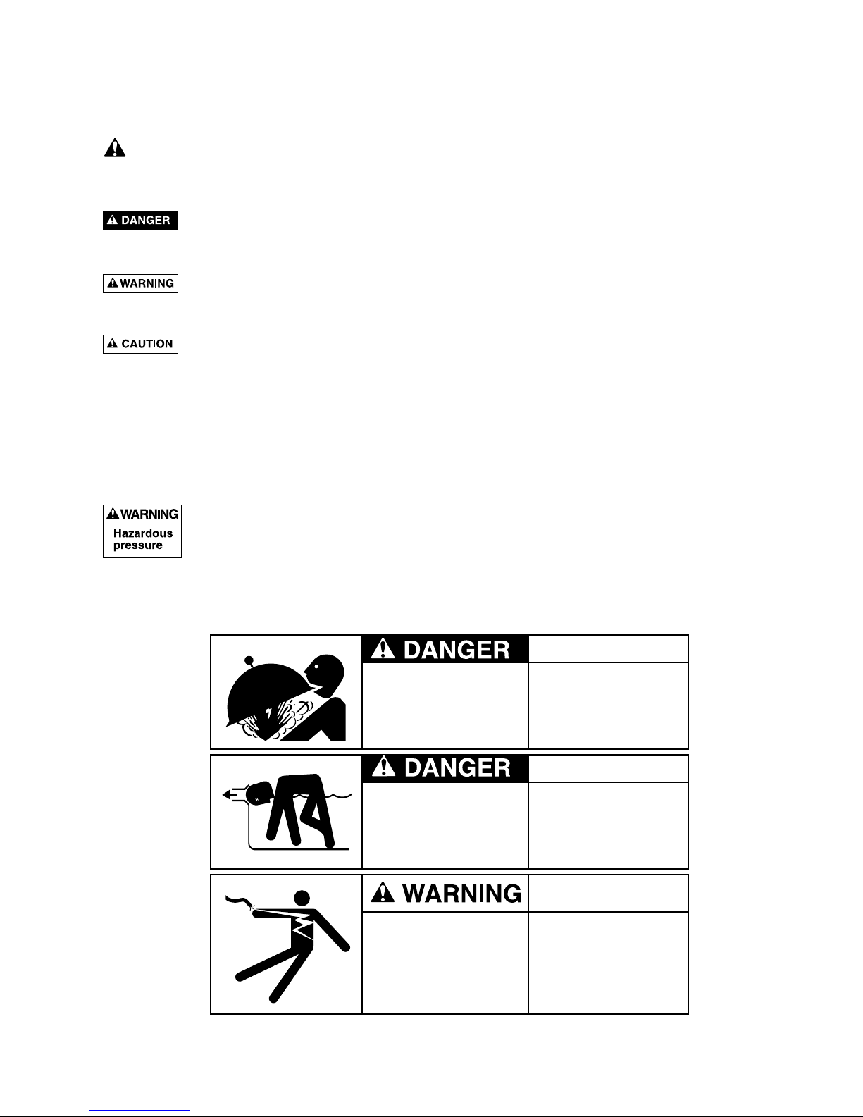
Hazardous Pressure!
Can cause tank
explosion.
WHEN USING SYSTEM:
Do not test with
compressed air
or operate above
rated pressure.
Hazardous voltage.
Can shock, burn,
or cause death.
BEFORE WORKING
ON PUMP OR MOTOR:
Unplug pump motor.
Hazardous suction.
Can trap or tear
hair or body parts,
causing severe injury
or death.
WHEN USING SYSTEM:
Do not block pump
suction or pool main
drain.
READ AND FOLLOW SAFETY INSTRUCTIONS!
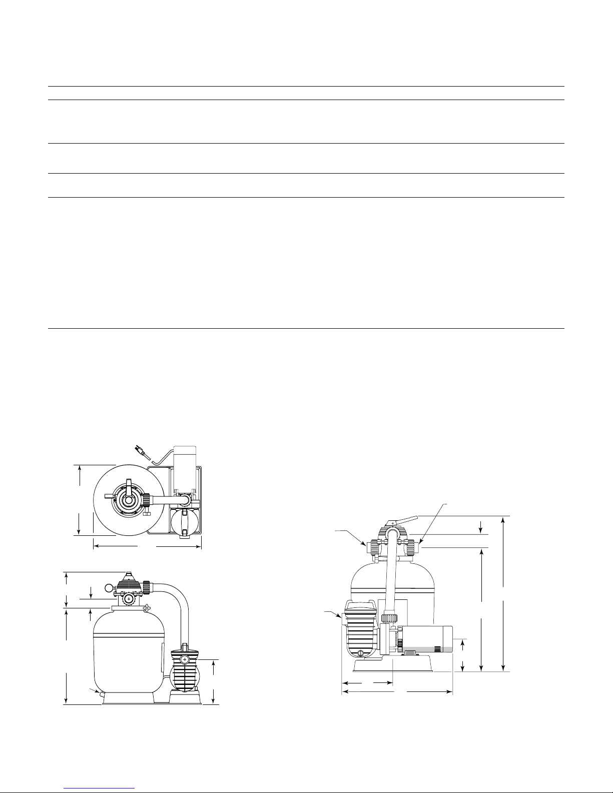
1-1/2" NPT
Return to Pool
(Union Connection)
1-1/2" NPT
Suction
Connection
1-1/2" NPT
Waste Outlet
(Union Connection)
23
2-13/16
A
B
7
11
1278 0994
Drain
(To Tank
Flange)
D
2-5/16
9-1/16
11-1/4
Tank
Dia.
C
E
1279 0994
4
TABLE I - OUTLINE DIMENSIONS IN INCHES (mm)
Filter Model A B C D E
15”(406mm) Filters 24 (610) 30-7/8 (784) 15-3/4 (400) 21-11/16 (551) 26-1/16 (662)
18”(457mm) Filters 26-9/16 (675) 33-5/16 (846) 17-3/4 (451) 24-1/4 (616) 27-1/16 (692)
21” (508mm) Filters 28-11/16 (729) 34-7/16 (875) 20-3/4 (527) 26-3/8 (670) 28-9/16 (725)
TABLE ll - FILTER SPECIFICATIONS AND OPERATING INFORMATION
FILTER MODEL: 15” 18” 21”
(JSAL15 Series) (JSAL180 Series) (JSAL210 Series)
Effective Filter Area 1.26 Ft.2(.117M2) 1.57 Ft.2(.223M2) 2.18 Ft.2(.203M2)
Max. Flow Rate 25.2 GPM(95 L/m) 31.5 GPM(123 L/m) 43.6 GPM(165 L/m)
Max. Operating Pressure 50 PSI(345 kPa) 50 PSI(345 kPa) 50 PSI(345 kPa)
M
ax. Operating Temperature 95° F(35°C) 95° F(35°C) 95° F(35°C)
Turnover in Hours:
6 Hours 9,070 Gal.(34 330 liters) 11,340 Gal.(42 922 liters) 15,700 Gal.(59 424 liters)
8 Hours 12,100 Gal.(45 799 liters) 15,120 Gal.(57 229 liters) 20,930 Gal.(79 220 liters)
10 Hours 15,120 Gal.(57 229 liters) 18,900 Gal.(71 536 liters) 26,160 Gal.(99 016 liters)
12 Hours 18,144 Gal.(68 675 liters) 22,680 Gal.(85 844 liters) 31,390 Gal.(118 811 liters)
Qty. of Media Required:
Cu. Ft. (cm
3
) 1(28 320cm3) 1.5(42 255cm3) 2(56 923cm3)
Weight in lbs.(kg) 100(45,4 kg) 150(68 kg) 200(90,7 kg)
NOTE: 1 cubic foot (28 320 cm3) of sand weighs approximately 100 lbs. (45,4kg). DO NOT use a finer grade of sand than recommended.
RECOMMENDED SAND GRADES:
Use only: #20 Silica Sand, Size Range .40-.55mm., Uniformity Coefficient less than 1.75.
NOTICE: Use of other sands will reduce filter performance, may damage pump, and will void warranty.
Recommended:
1. Wedron Silica/Best Sand Co., Sand Grade: Wedron .45-.55mm., Effective Size .46mm, Uniformity Coefficient 1.22.
2. U.S. Silica - Silurian Filter Sand, Sand Grade.45-.55 mm., Effective Size .48mm, Uniformity Coefficient 1.18.
Figure 1: Dimensions

5
GENERAL INFORMATION
• Clean a new pool as well as possible before filling
pool and operating filter. Excess dirt and large particles
of foreign matter in the system can cause serious damage to the filter and pump.
NEVER test this filter with compressed air.
Do not operate filter at water temperatures above
95°F (35°C).
NEVER operate this filter system at more than 50
pounds per square inch (50 PSI/345 kPa) pressure!
Plug system into electrically isolated, Ground Fault
Circuit Interrupter protected circuit ONLY!
• Clean a new pool as well as possible before filling
pool and operating filter. Excess dirt and large particles
of foreign matter in the system can cause serious damage to the filter and pump.
• Keep pool water pH at recommended level (7.2 to 7.6)
to avoid irritation to eyes and skin.
• The Hi-Rate Sand Filter System is designed for use
with above ground swimming pools only.
• Use only #20 Silica sand with a screen mesh of .45
to .55mm. Use of other sands will reduce filter
performance.
To reduce risk of electric shock, install
pump at least 10 feet from the inside wall of the pool.
Do not use an extension cord.
INSTALLATION
Trap to Pump Assembly:
Using four 5/16” cap screws, flat washers and lockwashers,
mount trap to pump body; be sure to install gasket between
trap and pump body. Tighten cap screws to 80 inch-lbs
(92 cm-kg) torque; do not overtighten.
Filter Mount Must:
• Provide weather and freezing protection.
• Provide space and lighting for easy access for routine
maintenance. (See Table I and Figure 1, Page 4, for
space requirements.)
• Be on a reasonably level surface and provide adequate
drainage.
• Be as close to pool as possible to reduce line loss from
pipe friction.
• Be solid – level– rigid – vibration free.
• Be installed so that trap suction inlet is below pool
water level at all times. This allows pump to prime.
• Have adequate ventilation to prevent motor
overheating.
Piping:
• Use teflon tape or Plasto-Joint Stik1on all male con-
nections of plastic pipe and fittings except unions. DO
NOT use pipe compounds on plastic pipe; it will
cause the pipe to crack. Do not use sealant or tape on
u
nions – assemble them dry and hand tight.
• Do not damage union sealing surfaces and “O” Rings.
• Support pipe independently to prevent strains on filter
and valve.
• Use 1-1/2 or 2" pipe to reduce pressure losses as much
as possible. If flex hose is used, use the type with
smooth internal walls.
• Fittings restrict flow; for best efficiency use fewest possible fittings.
• Keep piping tight and free of leaks: pump suction line
leaks may cause trapped air in filter tank or loss of
prime at pump; pump discharge line leaks may show
up as dampness or jets of water.
• When unions are provided, use as follows for leak free
connections:
1. O-Ring and sealing surfaces must be clean.
2. Assemble hand tight only (no wrenches).
3. No pipe compound or teflon tape on unions.
Valves:
• For servicing filter system and for cleaning pump trap,
install ball or gate valves
A. Between pump trap and pool skimmer, and
B. Between selector valve and return pipe to pool.
• A check valve installed between filter and heater will
prevent hot water from backing up into filter and deforming internal components.
• Use care before assembly not to damage union sealing
surfaces or O Ring.
Wastewater:
• Be sure all provisions for waste water disposal meet
applicable local, state or national codes. 100 gallons
(379 liters) or more of pool water will be discharged
during filter backwashing. Do not discharge where
water will cause flooding or damage.
1
Lake Chemical Co., Chicago, IL
6
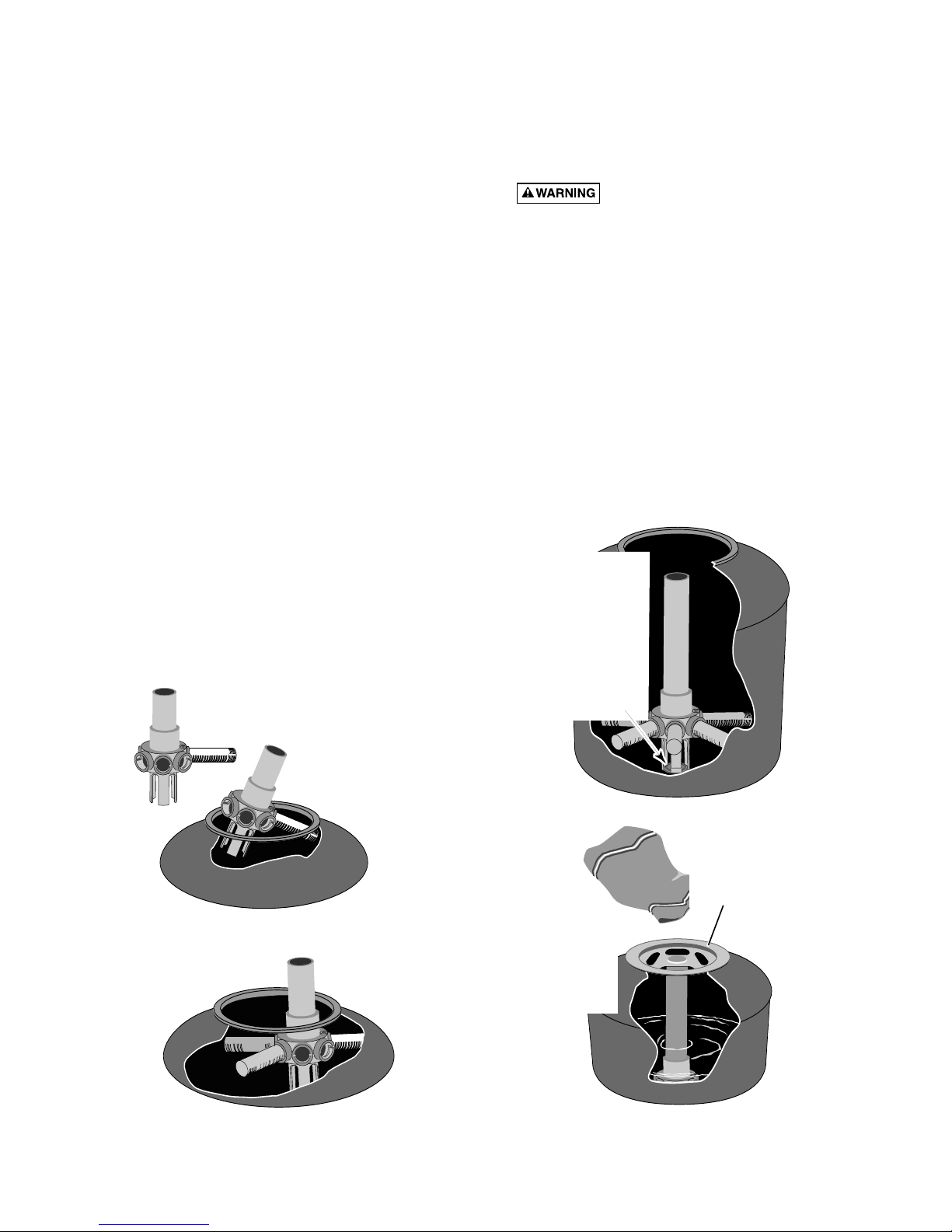
Filter Setup
Assembly: See Figures 2 through 5 for filter assembly.
Loading Sand Media
1. To keep sand out of collector assembly, place plastic
s
and shield over top of collector tube before pouring
sand into filter (See Figure 5).
2. To support laterals and prevent lateral breakage during loading, fill tank about half full of water before
loading sand.
3. Pour sand into filter tank. See “Recommended Sand
Grades”, Page 4, for correct type and quantity of sand
to use.
NOTICE: Make sure gasket area on top of tank is free
of sand before installing valve and clamp.
4. Before installing valve, double-check that correct
quantity of sand has been loaded (see Page 4).
5. Remove plastic sand loading shield and keep for future use.
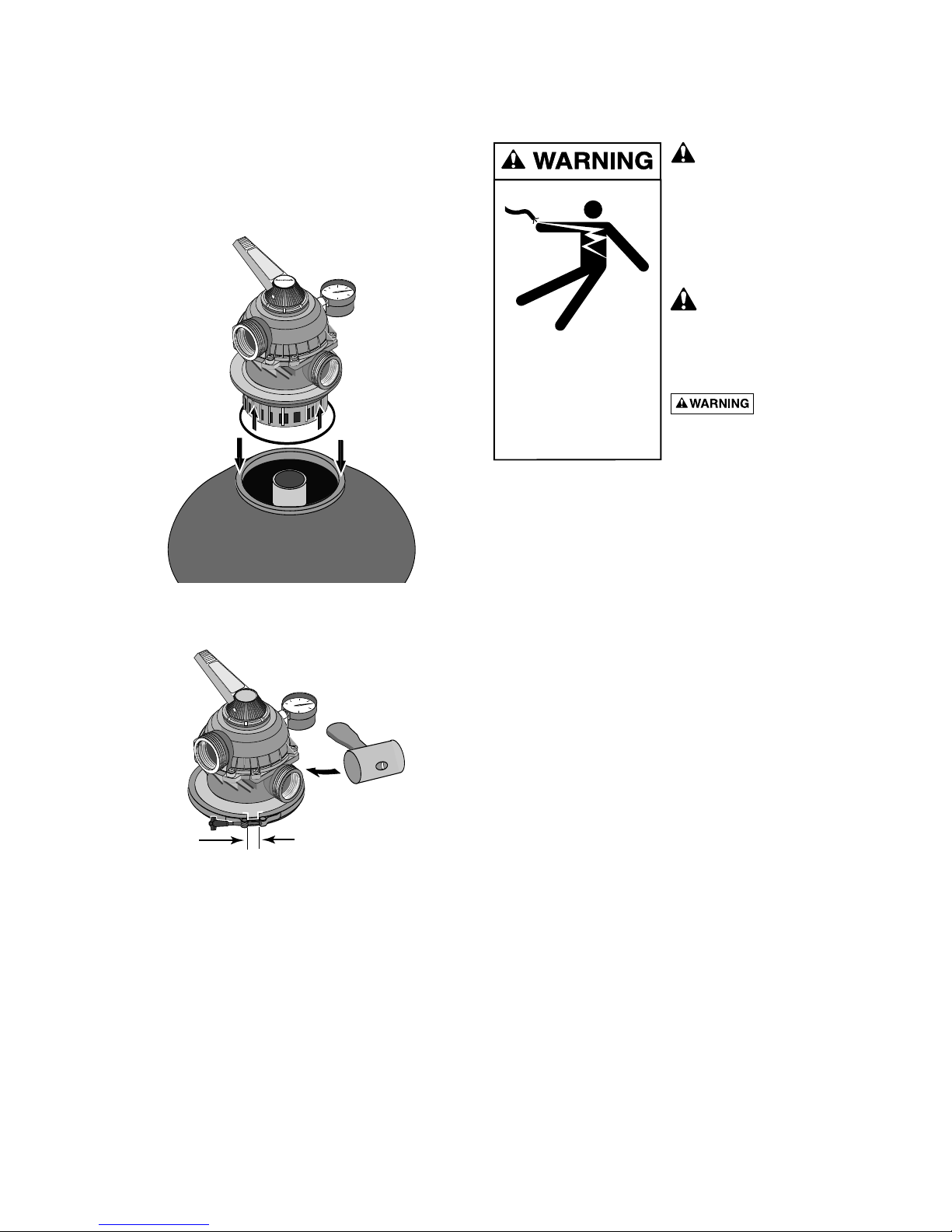
Valve Installation:
See Figures 6, 7, and 8
1. Install O-Ring on valve flange; make sure O-Ring is
clean, dry, and has no nicks, tears, or scrapes.
2. Make sure tank and valve flanges are clean and free of
sand; put valve on top of tank. Vertical pipe of collector assembly inserts into base of valve.
3. Install clamp; make sure knob is positioned for easy
access for filter maintenance. Valve port labeled
“
PUMP” should point toward pump.
4
. Tighten clamp knob until clamp ends (under bolt) are
1/4" (6mm) apart. Tap around outside of clamp with a
mallet to help seat clamp.
Hazardous pressure. Clamp will not
hold unless it is seated properly! DO NOT START
PUMP until clamp ends are 1/4" (6mm) apart or less.
5. If clamp will not pull up to 1/4" (6mm) gap, wait
15-30 minutes and retighten. Tap clamp gently with
mallet to help seat clamp.
6. Connect pipe from pump discharge to valve port labeled “PUMP”; use union half provided. Assemble
union as follows for leakfree operation:
A. O-Ring and sealing surfaces must be clean.
B. Assemble hand tight only (no wrenches).
C. NO pipe compound or teflon tape on unions.
7. Complete all plumbing connections (see Page 5 for
piping requirements).
A. Pipe from valve RETURN port to pool return.
B. Pipe from valve WASTE port to waste.
C. Suction piping from pool to trap inlet on pump.
B. Insert assembly
into top of
filter tank.
A. Insert first lateral into socket;
twist clockwise 1/4 turn
to lock lateral into hub.
Lateral is correctly installed
when slots face down.
731 0294
C. Hold assembly up
near top of tank and
add remaining
laterals.
732 0294
D. After all
laterals are
securely in
sockets,
position
assembly on
centering
boss in
bottom of
tank.
733 0294
S
A
N
D
::::
::::
::::
::::
::::
::::
::::
::::
::::
::::
::::
::::
::::
::::
::::
::::
::::
::::
::::
::::
::::
::::
::::
::::
::::
::::
::::
::::
::::
::::
::::
::::
::::
::::
::::
::::
::::
::::
::::
::::
::::
::::
::::
::::
::::
::::
::::
::::
::::
::::
::::
::::
::::
::::
::::
::::
::::
::::
::::
::::
::::
::::
::::
::::
::::
::::
::::
::::
::::
::::
::::
::::
::::
::::
::::
::::
::::
::::
::::
::::
::::
::::
::::
::::
::::
::::
::::
::::
::::
::::
::::
::::
::::
::::
::::
::::
::::
::::
::::
::::
::::
::::
::::
::::
::::
::::
::::
::::
::::
::::
::::
::::
::::
::::
::::
::::
::::
::::
::::
::::
::::
::::
::::
::::
::::
::::
::::
::::
::::
::::
::::
::::
::::
::::
::::
::::
::::
::::
::::
::::
::::
::::
::::
::::
::::
::::
::::
::::
::::
::::
::::
::::
::::
::::
::::
::::
::::
::::
::::
::::
::::
::::
::::
::::
::::
::::
::::
::::
::::
::::
::::
::::
::::
::::
::::
::::
::::
::::
::::
::::
::::
::::
::::
Fill tank
about
half full
of water
before
adding
sand.
Sand Shield
keeps collector
hub assembly
clean when
loading filter.
734 0294
Figure 2
Figure 3
Figure 4
Figure 5
7
8. System is ready for startup.
NOTICE: If there are leaks from beneath valve/clamp
area, STOP PUMP, release all pressure, remove clamp
and valve and clean sealing surfaces.
Follow directions under “Valve Installation”, Page 6,
when reinstalling valve. See Figures 6 and 7.
ELECTRICAL
Risk of electrical shock.
Plug pump into a
grounded, GFCI-protected 115
Volt circuit only. Incorrect voltage can cause fire or seriously
damage motor and voids warranty. Protect cord from water
and physical damage.
GFCI tripping indicates
an electrical problem. If
GFCI trips and will not reset,
have a qualified electrician inspect and repair electrical system.
Risk of electrical
shock. Unplug motor before
servicing or repairing pump or
motor.
Wiring:
Install a Ground Fault Circuit Interrupter (GFCI) in circuit; it will sense a short-circuit to ground and disconnect power before it becomes dangerous to pool users.
For size of GFCI required and test procedures for GFCI,
see manufacturer’s instruction.
In case of power outage, check GFCI for tripping (which
will prevent normal water circulation). Reset if necessary.
Match circuit breaker size to Table III, Page 8.
• Do not modify cord, plug, or receptacle. If an existing
circuit must be used and the receptacle and plug do
not match exactly, consult a licensed electrician.
• Do not use an extension or drop cord with this system;
it could cause a fire hazard or low voltage problems.
Wet cords cause shock hazards. Extension cords can
easily become cut or frayed and dangerous when
placed across yard areas or walkways.
Voltage:
Voltage at motor must be not more than 10% above or
below motor nameplate rated voltage or motor may
overheat, causing overload tripping and reduced component life. If voltage is less than 90% or more than 110%
of rated voltage when motor is running at full load, consult power company.
RR
EE
CC
II
R
R
C
C
U
U
L
L
AA
TT
EE
BB
AA
CC
KK
W
W
A
A
SS
H
H
EE
WW
A
A
S
S
T
T
E
E
FF
I
I
LL
TT
EE
R
R
1. Install O-Ring
on valve flange.
2. Install valve on tank.
Tank flange must
be clean; insert
collector pipe
into bottom
of valve.
Delavan, WI.
53115
USA
1/4" Max.
Port labeled
"PUMP" should
point toward
pump.
Install clamp
and tighten
until clamp
ends (under
bolt) are 1/4"
apart.
If unable to
close gap
to 1/4" or less,
wait 15-30
minutes and
retighten.
Tap around
clamp while
tightening to
help seat
clamp.
.WATERFORD, WI.
53185
U
SA
736 0294
R
R
EE
CC
I
I
RR
C
C
U
U
LL
AA
TT
EE
B
B
AA
C
C
KK
W
W
AA
SS
H
H
EE
WW
AA
S
S
TT
E
E
FF
I
I
LL
T
T
EE
R
R
Figure 6
Figure 7
Hazardous voltage.
Can shock, burn,
or cause death.
Disconnect power
before working
on pump or motor.
8
Table III–Recommended Fusing Data, 115 Volt 60 Hz Motors.
B
ranch
Pump Motor Full Load Circuit Breaker
M
odel No. H.P. Amps Rating (Amps)
JWPA5DC-2A3 3/4 9.4 15
JWPA5EC-2A3 1 11.9 15
J
WPS5FC-2A3 1-1/2SPL 11.9 15
1
7290-J1002 (2-Speed) 1 – 1/6 11.6/3.3 15
NOTICE: Values given are for pump motor only. Do not put
any other accessories on this circuit.
Table IV–Recommended Fusing Data, 115 Volt 60 Hz Single
Speed Motors.
Branch
Pump Motor Full Load Circuit Breaker
Model No. H.P. Amps Rating (Amps)
ABGS4EL-A2 1SPL 9.0 15
JWPA5DL-2A1, -2A2 3/4 9.0 15
JWPS5EL-A2 1SPL 9.0 15
JWPA5EL-2A1, -2A2 1 12.0 15
JWPAS5F-2A4U 1-1/2 SPL 12.0 15
JWPS5FL-A2 1-1/2 SPL 12.0 15
JWPA5FL-2A1, -2A2 1-1/2 16.0 20
Table V–Recommended Fusing Data, 230 Volt 60 Hz Motors.
Branch
Pump Motor Full Load Circuit Breaker
Model No. H.P. Amps Rating (Amps)
JWPA5E-230A2 1 6.1 15
Table VI–Recommended Fusing Data, 115 Volt 60 Hz 2-Speed
Motors.
Branch
Pump Motor Full Load Circuit Breaker
Model No. H.P. Amps Rating (Amps)
JWPA5YEL 1 / 1/8 11.7/3.39 15
JWPA5YFL 1-1/2 / 1/6 16.6/3.6 25
NOTICE Values given are for pump motor only. Do not put any
other accessories on this circuit.
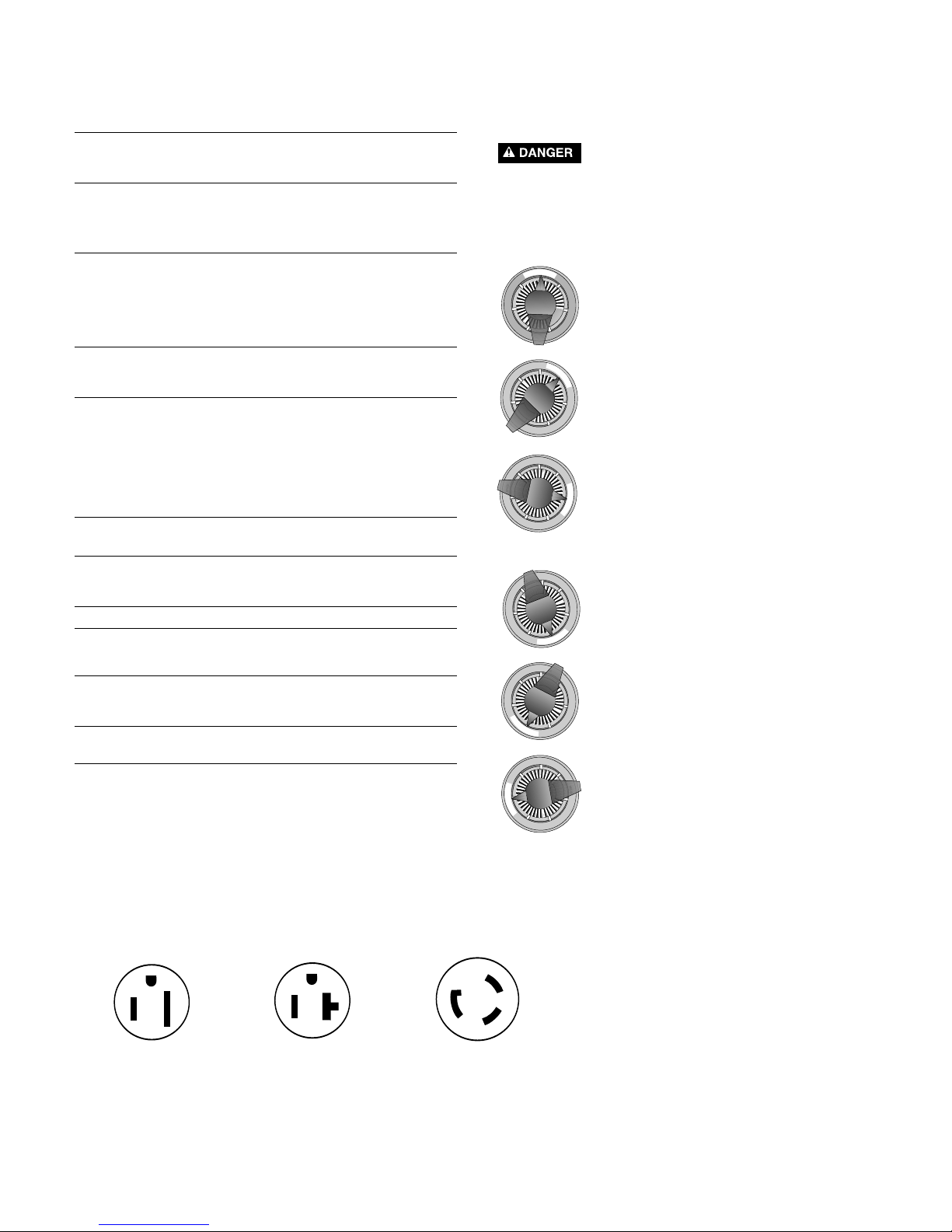
Startup/Operation
(
See Figure 9)
Hazardous suction. Can trap and tear hair
or body parts and can cause drowning. Do not block
pump suction. Small children using pool must ALWAYS
h
ave close adult supervision.
R
E
C
I
R
C
U
L
A
T
E
B
A
C
K
W
A
S
H
C
L
O
S
E
D
W
I
N
T
E
R
I
Z
E
W
A
S
T
E
F
I
L
T
E
R
R
I
N
S
E
Valve Setting
P
urpose/Flow
FILTER
Normal filtration and
v
acuuming; water goes
t
hrough filter to pool.
RINSE
F
or initial startup cleaning
and sand bed leveling
after backwash; water goes
through filter to waste.
RECIRCULATE
Circulates pool water;
bypasses filter.
R
E
C
I
R
C
U
L
A
T
E
B
A
C
K
W
A
S
H
C
L
O
S
E
D
W
I
N
T
E
R
I
Z
E
W
A
S
T
E
F
I
L
T
E
R
R
I
N
S
E
R
E
C
I
R
C
U
L
A
T
E
B
A
C
K
W
A
S
H
C
L
O
S
E
D
W
I
N
T
E
R
I
Z
E
W
A
S
T
E
F
I
L
T
E
R
R
I
N
S
E
737 0294
BACKWASH
Reverses flow for
cleaning; water
goes through filter
to waste.
CLOSED
Shuts off all flow to
filter and pool.
WINTERIZE
Leaves all valve ports
partially open for
winter storage.
R
E
C
I
R
C
U
L
A
T
E
B
A
C
K
W
A
S
H
C
L
O
S
E
D
W
I
N
T
E
R
I
Z
E
W
A
S
T
E
F
I
L
T
E
R
R
I
N
S
E
Valve Setting
Purpose/Flow
R
E
C
I
R
C
U
L
A
T
E
B
A
C
K
W
A
S
H
C
L
O
S
E
D
W
I
N
T
E
R
I
Z
E
W
A
S
T
E
F
I
L
T
E
R
R
I
N
S
E
R
E
C
I
R
C
U
L
A
T
E
B
A
C
K
W
A
S
H
C
L
O
S
E
D
W
I
N
T
E
R
I
Z
E
W
A
S
T
E
F
I
L
T
E
R
R
I
N
S
E
738 0294
Figure 8
3/4 and 1 HP Models with
–A2 suffix use15-amp
straight outlet, above.
1-1/2 HP Models with
–2A2 suffix use 20-amp
straight outlet, above.
All models with –A1 or
–2A1 suffix use 20-amp
twist-lock outlet, above.
NOTICE: Determine circuit breaker rating from Table III, above.
Determine correct outlet required from illustration below.
“ABG” and “JWP” 3/4 and 1 HP
Models with A2,
-2A2 and -A2U suffix and
1-1/2 HP Models with -2A4U
suffix use 15-amp straight
outlet, above.
“ABG” and “JWP” 1-1/2 HP
Models with A2,
-2A2 and A2U suffix use
20-amp straight outlet, above.
All “ABG” and “JWP” Models
with A2, -2A1 suffix use 20-amp
twist-lock outlet, above.
9
Hazardous pressure. To avoid explosion
a
nd possible severe or fatal injury, filter system pressure
m
ust not exceed 50 PSI (345 kPa) under any circumstances. NEVER test this filter system with compressed
air; never operate system with water temperature above
95° F (35° C).
To prevent equipment damage and possible
injury, turn pump OFF before changing valve position.
NOTICE: Do not add chemicals directly into the pool
skimmer. Adding undiluted chemicals may damage
equipment and void warranty.
1. Open system valves and make sure pump is filled
with water.
Make sure pool water level is above skimmer or the
suction outlet.
2. With pump OFF, set valve to ‘BACKWASH’ position.
3. Start pump, circulating water backwards through filter to waste.
4. Backwash until water runs clear (3-5 minutes).
5. Stop pump; set valve to ‘RINSE’ position.
6. Start pump; run pump for one minute.
7. Stop pump; set valve to ‘FILTER’ position.
8. Filter is now ready for service.
9. Record clean starting filter pressure gage reading as a
reference.
10. When pool is first filled, backwash once a day until
pool water is sparkling clear. After that, backwash
when pressure gage shows 5 to 7 PSI (34.5 to 48
kPa) higher than starting pressure.
MAINTENANCE
General:
•
Wash outside of filter with a mild detergent and water.
R
inse off with hose.
NOTICE: DO NOT use solvents to clean filter; solvents
may damage plastic components in system.
• Inspect sand bed at least once a year to remove foreign material which has not been backwashed out of
system.
NOTICE: When the sand bed gets hard and crusty on
top, remove all the old sand and replace it with new
sand.
Weekly Pool Equipment Inspection:
1. Check pressure during operation. When pressure is 5
to 7 PSI (34.5 to 48 kPa) higher than initial operating
pressure, backwash filter (see instructions under
“Startup/Operation”).
2. Except during hot weather with heavy swimmer loads,
operating filter 6 to 12 hours per day should be sufficient. Carefully monitor water chemical balance and follow recommendations of your local pool professional.
Water Maintenance
• Keep water level at least two inches above bottom of
skimmer opening when system is not in operation.
Failure to do so can allow air to enter system, causing
pump to lose prime and filter to entrap air.
• Maintain pH at 7.2 to 7.6 in pool.
To prevent damage to system components, keep
water temperature below 95° F (35° C) at all times.
Vacuum Pool:
1. Fill vacuum hose by submerging in water from one
end to the other.
2. To vacuum, insert hose into skimmer suction manifold
or into vacuum line in pool wall. See instructions provided by pool builder or pool manufacturer. Start
pump, making sure it is primed and pumping.
3. After vacuuming, clean pump trap to remove accumu-
lated debris, then check filter pressure gage. If reading
is 5 to 7 PSI (34.5 to 48 kPa) higher than initial operating pressure, backwash filter
Lower or Drain Pool
(See Figure 10, Page 10)
1. Turn pump ‘OFF’; set valve handle to ‘WASTE’.
2. Use vacuum cleaner hose and head.
3. Start pump; run until pool is lowered to desired level.
4. Turn pump ‘OFF’; set valve handle to ‘FILTER’.
5. Start pump.
R
E
C
I
R
C
U
L
A
T
E
B
A
C
K
W
A
S
H
C
L
O
S
E
D
W
I
N
T
E
R
I
Z
E
W
A
S
T
E
F
I
L
T
E
R
R
I
N
S
E
R
E
C
I
R
C
U
L
A
T
E
B
A
C
K
W
A
S
H
C
L
O
S
E
D
W
I
N
T
E
R
I
Z
E
W
A
S
T
E
F
I
L
T
E
R
R
I
N
S
E
R
E
C
I
R
C
U
L
A
T
E
B
A
C
K
W
A
S
H
C
L
O
S
E
D
W
I
N
T
E
R
I
Z
E
W
A
S
T
E
F
I
L
T
E
R
R
I
N
S
E
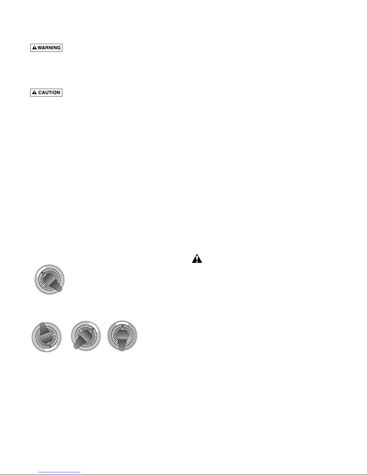
Figure 9: Valve settings for startup. Stop
pump before changing valve position.
WASTE
Lowers pool level or
drains pool; water
bypasses filter,
goes to waste.
Valve Setting
Purpose/Flow
R
E
C
I
R
C
U
L
A
T
E
B
A
C
K
W
A
S
H
C
L
O
S
E
D
W
I
N
T
E
R
I
Z
E
W
A
S
T
E
F
I
L
T
E
R
R
I
N
S
E
743 0294
10
STORAGE/
WINTERIZING
P
ool chemicals may give off corrosive
f
umes. Store chemicals away from system in a well ven-
tilated area.
NOTICE: Allowing water to freeze will damage filter and
void warranty. If antifreeze is needed, use propylene glycol;
it’s plastic compatible and non-toxic. Follow manufacturers
instructions. Do not use ethylene glycol based anti-freeze –
it’s toxic and it may damage plastic components.
1. Open all system valves. Set multiport valve at ‘WINTERIZE’ to allow air passage to all ports (Figure 11).
2. Remove drain plug from filter.
3. Drain filter tank completely and replace drain cap
(Figure 12).
4. Cover with plastic or tarpaulin to protect from
weather.
5. Remove drain plugs from pump.
6. Protect from freezing.
Startup for Winterized Equipment:
1. Remove any temporary weather protection placed
around system for shutdown.
2. See “Startup”, Page 8, for reactivation of the filter.
3. Inspect all electrical wiring to pump for damage or
deterioration over the shutdown period. Have a qualified serviceman repair/replace wiring as needed.
Inspect and tighten all watertight connections.
4. Open all valves in suction and return piping.
5. Remove any winterizing plugs in system.
6. Drain all winterizing chemicals (if used) from system;
flush system.
7. Close all drain valves and replace all drain plugs in
system.
8. Fill pool with water to proper level (see pool maufacturer’s instructions).
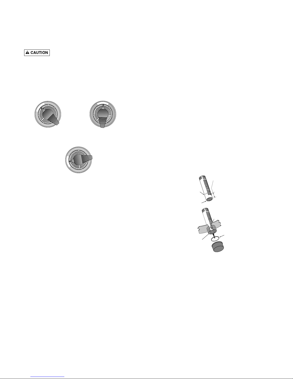
Drain Fitting Installation/Removal
NOTICE: If pool is above height of filter, first close
valves in pump suction and return lines to prevent draining pool. If there are no shutoff valves installed, disconnect suction and return lines and raise ends above pool
w
ater level.
1. Installation: See Figure 12.
2. To Drain Filter:
A. Remove drain cap. Lateral tube should remain in
place inside drain opening to prevent sand from
draining out.
B. Open union coupling on backwash port of Multi-
Port valve. This will allow air into filter and allow
water to drain from filter tank.
C. Replace cap when tank is empty.
3. Removing Sand From Filter:
A. Remove both drain cap and slotted lateral tube (see
Figure 12). Sand and water will drain from tank.
B. To completely flush filter tank of sand, remove top
clamp and multiport valve and flush the inside of
the tank with a hose.
C. Thoroughly clean sand from all parts and from tank
drain opening before reassembling drain fitting.
R
E
C
I
R
C
U
L
A
T
E
B
A
C
K
W
A
S
H
C
L
O
S
E
D
W
I
N
T
E
R
I
Z
E
W
A
S
T
E
F
I
L
T
E
R
R
I
N
S
E
R
E
C
I
R
C
U
L
A
T
E
B
A
C
K
W
A
S
H
C
L
O
S
E
D
W
I
N
T
E
R
I
Z
E
W
A
S
T
E
F
I
L
T
E
R
R
I
N
S
E
Figure 10: Valve settings to lower pool water level.
Stop pump before changing valve position.
R
E
C
I
R
C
U
L
A
T
E
B
A
C
K
W
A
S
H
C
L
O
S
E
D
W
I
N
T
E
R
I
Z
E
W
A
S
T
E
F
I
L
T
E
R
R
I
N
S
E
Figure 11: Valve setting for winter storage.
Stop pump before changing valve position.
About 1"
Small
O-Ring
Open end
of lateral
Seat small
O-Ring
Large
O-Ring
End of lateral is
flush with end of
drain fitting
746 0294
Figure 12: Drain Fitting Assembly. This assembly allows water to drain without losing the sand out of
the filter tank.
Make sure all surfaces are clean and free of sand.
Don’t cross thread cap; don’t overtighten cap.
11
MULTI-PORT VALVE SERVICE
Hazardous pressure. Stop pump and release all pressure from system before working on filter,
valve, or clamp.
NOTICE: If Multi-Port valve is below pool water level,
close suction and discharge valves before disassembly to
prevent draining pool.
Handle Replacement:
1. Stop pump.
2. Place handle in ‘FILTER’ position.
3. Remove pin (Key 1, Figure 13) to disconnect handle. If
it cannot be removed by hand, use a hammer and center punch and lightly tap it out.
4. Remove handle; replace with a new one. Be sure new
handle is in ‘FILTER’ position.
5. Replace pin.
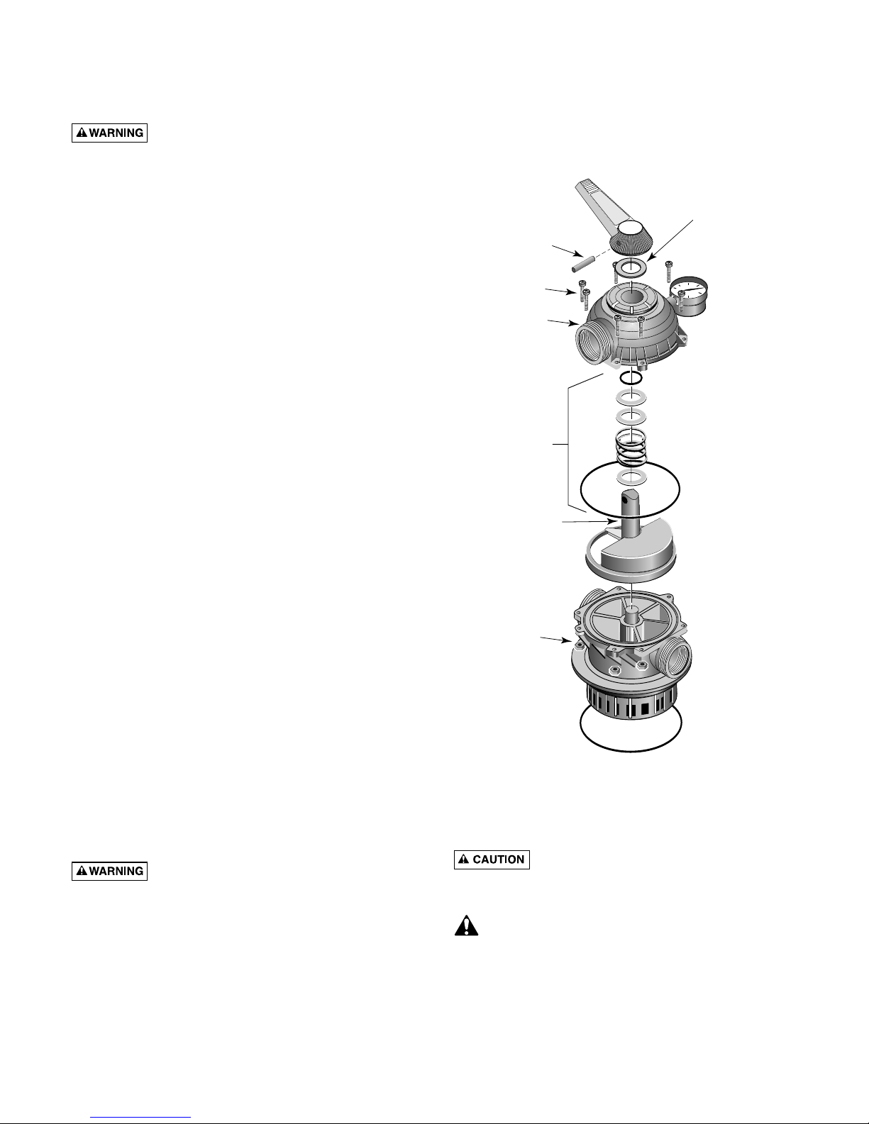
Lid and Plug replacement:
A. Remove Handle (see ‘Handle Replacement’, above).
B. Remove plug:
1. Remove all screws and nuts (Key Nos. 2 and 6,
Figure 13).
2. Remove lid (Key No. 3) by pulling straight up while
holding plug shaft (Key No. 5) down with thumb.
C. Inspect Internal Parts:
Inspect plug and gasket spring, O-Rings, and internal
washers (Key No. 4). Replace if necessary.
D. Reassemble Valve:
1. Replace plug gasket and shaft, mounting spring,
washers, and O-Ring on plug shaft. Lubricate ORing with Amojel.
2. Replace lid; match screw holes in lid and body.
3. Press down on lid to allow screws to engage nuts;
tighten each nut securely.
4. Replace top washer (Key No. 1A) and handle, making sure indexing pin on plug shaft points in same
direction as pointer on handle. Replace handle pin.
5. Tighten all lid screws to 55 inch-lbs. (63.4 kg-cm)
torque.
Valve Removal
Hazardous pressure. Stop pump and release all pressure from system before working on filter,
valve, or clamp.
NOTICE: If multi-Port Valve is below pool water level,
close suction and discharge valves before disassembly to
prevent draining pool.
1. Disconnect piping from pump and pool.
2. Remove clamp.
3
. Remove valve from filter top.
4. To reinstall valve, follow “Valve installation” instruct
ions, Page 6. BE SURE to follow clamp tightening in-
s
tructions.
PUMP SERVICE
To protect against possible electric shock,
use only identical replacement parts when servicing.
System should only be serviced by qualified personnel.
Before removing trap cover:
1. STOP PUMP before proceeding.
2. CLOSE GATE VALVES in suction and discharge pipes.
3. RELEASE ALL PRESSURE from pump and piping
system.
R
E
C
I
R
C
U
L
A
T
E
B
A
C
K
W
A
S
H
C
L
O
S
E
D
W
I
N
T
E
R
I
Z
E
W
A
S
T
E
F
I
L
T
E
R
R
I
N
S
E
1
1A
2
3
4
5
6
Aquatools
.
WATERFORD, WI.
5
3185
U
SA
744 0294
Figure 13: Valve Disassembly
12
To avoid dangerous or fatal electrical shock haza
rd, turn OFF power to motor before working on
p
ump or motor.
Trap needs no lubrication or regular maintenance bey
ond reasonable care and periodic cleaning of strainer
basket.
If shaft seal is worn or damaged, repair as follows:
Pump Disassembly:
1.Unplug motor before servicing or repairing pump or
motor.
2.Close all valves in suction and discharge piping.
3.Remove drain plugs from the bottom of pump and
trap; drain pump completely.
4.Disconnect pipe unions (or clamps) on suction and
discharge piping. Remove hold down bolts and withdraw complete pump/motor/trap assembly.
5.Remove cap screws (Key No. 16, Pages 15 and 16)
from front plate (Key No. 13). Remove front plate
with trap (Key No. 20) attached. Remove and inspect
O-Ring (Key No. 12).
6.Remove end cap (Key No. 2) from motor cover (Key
No. 7). NOTICE: JWP Series pump motors do not
have a motor cover or switch.
7.Hold motor shaft with 7/16” wrench on flats on
motor shaft; unscrew impeller (Key No. 11).
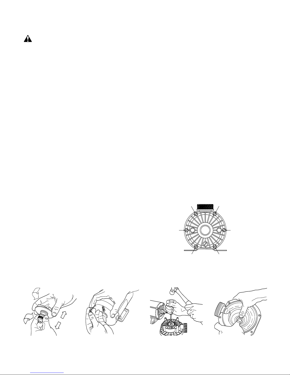
8.Carefully remove rotating half of seal (Key No. 10)
from impeller sleeve. Twist as you pull; make sure
you do not damage surface of sleeve where seal both
seats and seals. See Figure 14.
9.Remove motor throughbolts (see Figure 15). Remove
seal plate (Key No. 9). Tap stationary half of seal out
of seal plate (see Figure 16).
10. If necessary, disconnect electrical wiring from motor
terminal board and remove motor (Key No. 6) from
motor cover (Key No. 7).
Pump Assembly:
1. Examine seal cup and O-Rings. Replace anything that
shows signs of wear or damage.
2. Check the shaft seal (Key No. 10, Pages 15 and 16)
for scoring, scratches, chips, etc., and for any signs of
damage to spring or retainer. Replace if any wear or
damage is visible.
3.Press stationary half of seal into seal plate (Key No. 9)
using finger pressure only (see Figure 17). Make sure
s
eal is firmly and evenly seated.
4.Install rotating half of seal on impeller sleeve. Push it
onto sleeve until it butts against back of impeller.
5.Insert impeller sleeve through center hole in seal
plate (Key No. 9). Thread slinger (Key No. 8) over the
end of the impeller sleeve.
6.If motor has been removed from motor cover, reinstall it now. Set up seal plate (Key No. 9) in front of
motor cover; hold motor shaft with 7/16” wrench on
shaft flats (under cap) and thread impeller through
center hole in seal plate onto shaft). Make sure that
slinger is in place on impeller sleeve – not loose on
shaft.
7.Install motor throughbolts; make sure seal plate butts
firmly against motor endbell. If necessary, install
motor cover and switch.
8.Install wear ring on back of front plate.
NOTICE: Teeth on wear ring interlock with ribs in
front plate.
9.Install front plate (Key No. 13). Tighten cap screws in
sequence as shown in Figure 18; tighten to 30 inchlbs. (34.5 cm-kg.) torque.
10.Reinstall drain plugs; reinstall pump and motor on
base and tighten hold-down bolts.
11. Reconnect unions; tighten hand tight only.
Figure 14 Figure 15 Figure 16 Figure 17
#1
#6
#2
#5 #3
#4
Start
Here
Figure 18: Pump front Plate Torque Sequence.
 Loading...