

Waterford ERIN 90 T/V, ERIN 90 R/V Installation & Operating Instructions
ERIN 90 T/V & R/V
WoodBurning Stove
IMPORTANT
This stove has two U.s. Environmental Protection Agency Temporary labels on the front door. One of the labels
reads; “Heat output 10,200 to 39,900 BTU’s/Hr (5.7 grams per hour) 63% efficiency.” This label shows the performance of the unit when connected to a Rear Exit configuration.
The second label reads; “Heat output 10,500 to 40,900 BTU’s/Hr. (4.2 grams per hour), 63% efficiency. This
label shows the performance of the unit when connected to a Top Exit configuration.
SAFETY NOTICE
Please read this entire manual before you install and use your new room heater. Failure to follow instructions
may result in property damage, bodily injury or even death.
If this stove is not properly installed, a house fire may result. For your safety, follow the installation directions.
Contact local building or fire officials about restrictions and installation inspection requirements in your area.
The stove must be connected to a UL/ULC listed high temperature residential type H.T. and building heat appliance chimney or an approved masonry chimney with flue liner.
MANUFACTURED BY: WATERFORD STANLEY LIMITED,
BILBERRY, WATERFORD, IRELAND.
INSTALLATION & OPERATING INSTRUCTIONS
WATERFORD ERIN 90 WOODBURNING STOVE INSTALLATION
& OPERATING INSTRUCTIONS
GENERAL
When installing, operating and maintaining your
Waterford Erin 90 T/V & R/V Stove respect basic
standards of fire safety. Read these instructions
carefully before commencing the installation.
Failure to do so may result in damage to persons
and property. Consult your local Municipal office
and your insurance representative to determine
what regulations are in force. Save these instructions for future reference.
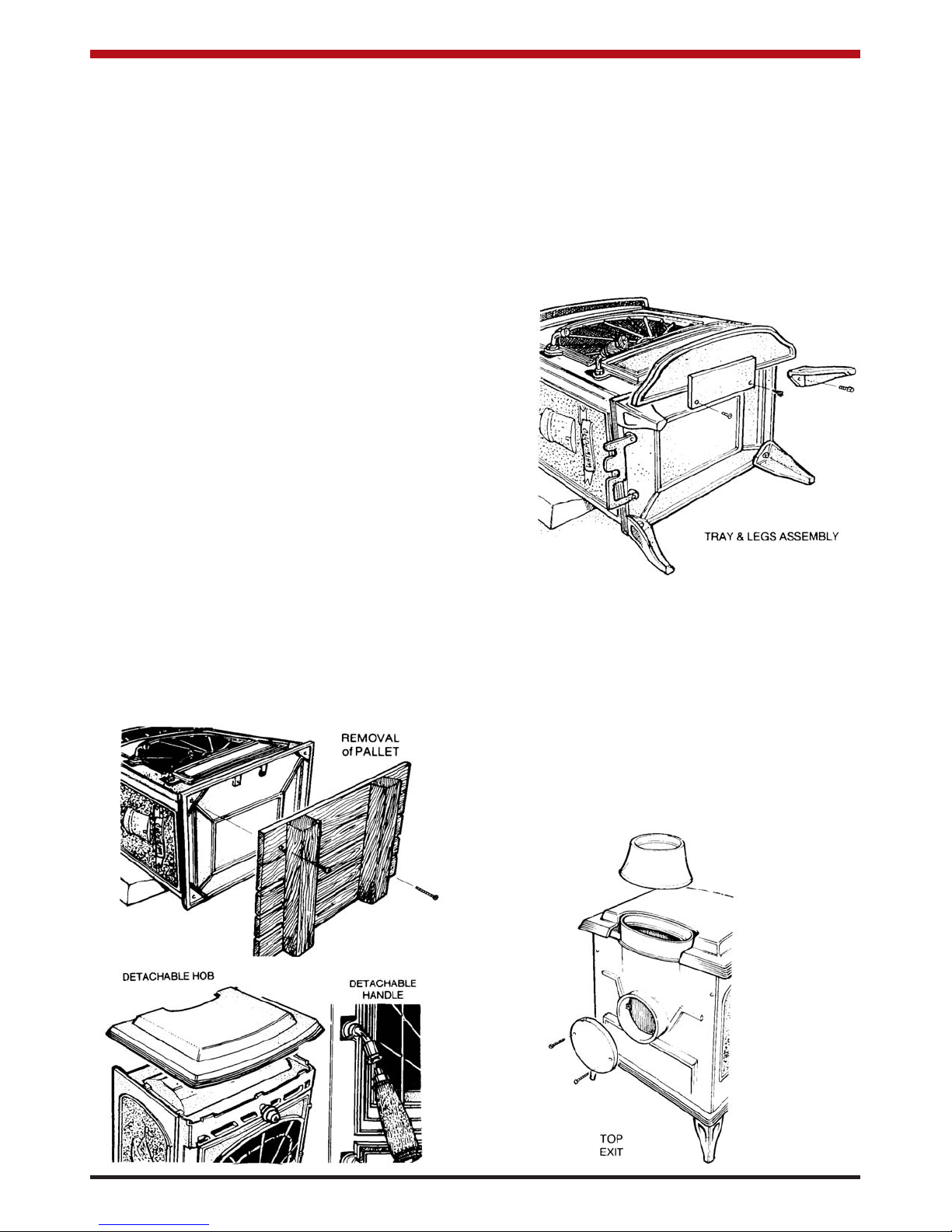
PRE-INSTALLATION ASSEMBLY
(a) After removing the stove from its packing,
open the ashpit door (item 9 in exploded
view) and remove the contents.
(b) Open the firedoor (item 8) using the detach
able handle - found in the ashpan (item 36)
and remove the contents of the firebox, leav
ing the bricks in place.
(c) Remove the ash lip (item 19) from the rear of
the stove if you have not already done so.
Remove the loose fitting hob and place on a
non-abrasive surface.
(d) Place the plastic packing on the ground at
the back of the stove and lay the stove on its
back on top of the packing.
(e) Remove the wooden pallet by taking out the
two retaining screws from the base of the
stove.
(f) Fit the four legs (item 2) to the base (item 1)
of the stove with the four 5/8” x 5/16” screws
provided. Fit the ash lip with the two 3/4” x
1/4” screws provided. Fit the tool carrier to
the left side of the base with the two 3/4” x
1/4” screws provided. Tighten all screws.
Stand the stove upright taking care not to
strain the back leg bolts.
THIS STOVE MAY BE CONNECTED TO EITHER A
TOP OR REAR EXIT.
TOP FLUE EXIT
Take the top flue spigot (item 6). Place a small
amount of fire cement on the inside flange of the flue
outlet (item 18) before fitting it to the stove. Push the
flue spigot (item 6) into place, making sure that it is
fully sealed to the stove. Any excess cement on the
inside of the flue spigot should be removed to prevent any obstruction of the flue passage.
2
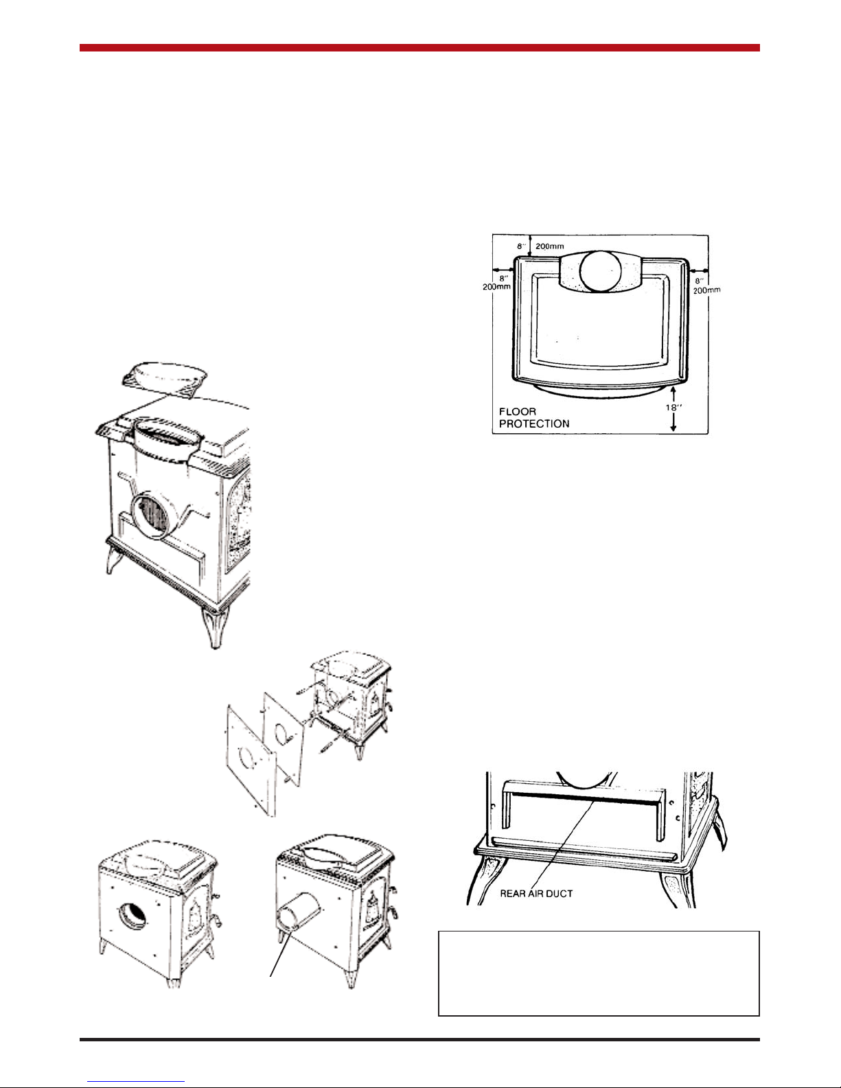
REAR FLUE EXIT
Fit the top cover plate (item 5) to the stove with the
screws holding on the rear exit cover plate (item 68).
Make sure that all the sealing rope is properly
sealed to the stove flue outlet (item 18).
HEAT SHIELD
Fit the rear heat shield as follows: Screw the four 4”
x 1/4” bolts (item 69) to the back plate (item 23). Fit
the four 2” spacers (item 70) over the tie bolts. Fit
the inner heat shield (item 75) without the blanking
plate (item 72) onto the four tie bolts. Now fit the 1”
spacers (item 71) over the tie bolts and fit the outer
heat shield panel (item 76) without the blanking plate
(item 72). Tighten the whole assembly together
using the four 1/4” nuts provided.
FLOOR PROTECTION
When installing this heater on a combustible floor, a
floor protector, consisting of a layer of non-combustible material at least 3/8” thick or 1/4” thick covered with 1/8” sheet metal is required to cover the
area under the heater and to extend to at least 18”
at the front and 8” to the sides, and embers which
may fall out from the door when stoking or fuelling.
LOCATION
There are several conditions to be considered when
selecting a location for your Waterford Erin 90 T/V &
R/V Stove.
(a) Distance from a safe chimney.
(b) Position in the area to be heated - central
locations are usually best.
(c) Allowance for proper clearances to com
bustibles.
(d) Obstruction in the ceiling, upper floor or roof,
for example, ducting plumbing, electrical fit
tings and wiring, overhead fixed furnishings
etc.
WARNING
DO NOT OBSTRUCT FREE AIR SUPPLY TO THE
SECONDARY AIR DUCT AT THE REAR OF THE
STOVE.
3
With rear heatshield fitted
for rear outlet configuration.
Rear heat
shield fitted
complete with
shielded chimney connector
for a rear outlet
configuration.
Chimney connector and pipe
shield not supplied as standard.
1 inch space
REAR
EXIT
FITTING OF REAR HEAT
SHIELD
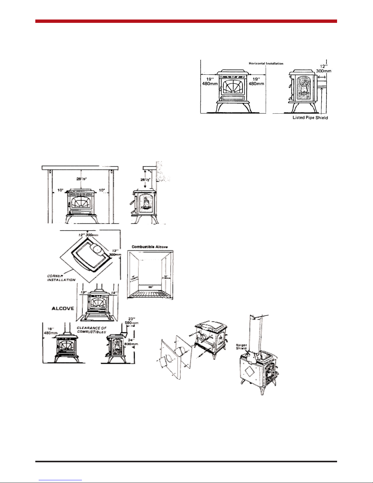
MINIMUM CLEARANCES TO COMBUSTIBLES
From the front of the stove 48” - 1200mm
From back of stove 24” - 600mm
From the side of stove 19” - 480mm
From corner installation 12” - 300mm
From the flue pipe 23” - 580mm
Mantle clearance 26 1/2” - 675mm
Side trim, which extends
less than 2” from the face
of the fireplace 10” - 250mm
MANTLE & TRIM CLEARANCES
If the stove is to be installed using the rear exit
option then the UL/ULC listed Optional rear heat
shield must be fitted together with a listed pipe
shield fitted from the heat shield to the back wall on
the underside of the chimney connector.
(See horizontal installation).
Rear Exit
From back of stove 12” - 300mm
From side of stove 19” - 480mm
plate (item 72) and the double top flue spigot shield
(item 74) over the tie bolts and tighten the whole
assembly together using the four
1/4” nuts provided.
When the Waterford listed heat shields are used
together with a listed pipe shield using the top exit
option the clearances may be reduced to 9
1/2”.
(Pipe shield and heat shields are not supplied as
standard.
4
REDUCED CLEARANCES
Under certain conditions the minimum clearances
may be reduced by means of:
(a) Listed Waterford rear heat shield assembly
installed in accordance with the manufactur
ers instructions.
(b) Shields constructed in accordance with
NFPA211 (USA) Can3-B365 installation
code for solid fuel fired appliances.
(c) Fitting the listed Waterford Heat Shield and
chimney connector pipe shield.
REAR HEAT SHIELD
If the stove e is to be connected to a top flue exit
then the rear heat shield assembly must be fitted as
follows: Screw the four 4” x 1/4” heat shield tie bolts
(item 69) to the back plate (item 23). Fit the four 2”
spacers (item 70) over the heat shield tie bolts. Fit
the inner heat shield (item 75) complete with rear
heat shield blanking plate (item 72) onto the four
heat shield tie bolts. Now fit the four 1” spacers
(item 71) over the tie bolts and fit the outer heat
shield (item 76) complete with heat shield blanking
1 inch spacer
Fitting of listed pipe
shield.
Pipe shield and chimney
connector are not supplied as standard with
the stove
.
Fitting of rear heat
shield
 Loading...