

Waterford 104 MK II Installation And Operating Instructions
104 MK II WOOD-BURNING STOVE
SAFETY NOTICE
PLEASE READ THIS ENTIRE MANUAL BEFORE YOU INSTALL AND USE YOUR NEW ROOM HEATER. FAILURE TO
FOLLOW INSTRUCTIONS MAY RESULT IN PROPERTY DAMAGE, BODILY INJURY OR EVEN DEATH. SAVE THESE
INSTRUCTIONS FOR FUTURE REFERENCE.
IF THIS STOVE IS NOT PROPERLY INSTALLED, A HOUSE FIRE MAY RESULT. FOR YOUR SAFETY, FOLLOW THE
INSTALLATION DIRECTIONS. CONTACT LOCAL BUILDING OR FIRE OFFICIALS ABOUT RESTRICTIONS AND
INSTALLATION IN YOUR AREA.
THIS STOVE MUST BE CONNECTED TO A LISTED HIGH TEMPERATURE RESIDENTIAL TYPE AND BUILDING HEATING APPLIANCE CHIMNEY OR AN APPROVED MASONRY CHIMNEY WITH FLUE LINER.
MANUFACTURED BY: WATERFORD STANLEY (MARKETING) LIMITED
BILBERRY, WATERFORD, IRELAND.
INSTALLATION AND OPERATING INSTRUCTIONS
104 - MKII
PRE-INSTALLATION ASSEMBLY
Step 1:
After removing the stove from the pack, open the fire door
and remove packed contents from the Firebox. Empty
the Jiffy Bag.
Step 2:
Lay the stove on its side. Insert and secure a leg in the
recess at each corner of the base using 25mm x 6mm (1
in. x 1/4 in.) flat head screws and 6mm (1/4 in.) flat washers.
Step 3:
Carefully stand the unit upright on its legs.
Step 4:
Remove the nut and washer from the knob. Place in position, insert the screw in position with spring washer and
nut provided. See Sketch.
104 MK II
GENERAL INSTRUCTIONS
BUILDING CODES
Consult the LOCAL BUILDING CODE in all cases as to
the particular requirements concerning the installation of
SOLID FUEL TYPE ROOM HEATERS. This 104 MK II
WOOD BURNING STOVE is intended to be installed in
accordance with National Fire Protection Associations
Standard for Chimneys, Fireplaces and Vents, NFPA 211-
1977.
This stove has been tested and listed by UNDERWRITERS LABORATORIES INC, and as such carries the U.L.
and U.L.C. LABEL. All building codes which recognise
the value of U.L. Listing will accept applications for and
approve installations of this product.
INSTALLATION INSTRUCTIONS
MUST BE FOLLOWED.
CHIMNEYS
The 104 MK II Wood Stove is a Radiant Room Heater and
must be connected to a CHIMNEY of the proper size and
type.
The complete installation must be done in accordance
with current Standards and Local Codes. It should be
noted that the requirements and these publications may
be superseded during the life of this manual.
The chimney must have a CROSS-SECTIONAL AREA of
at least 182.39 sq. cm. (28.27 square inches). It is best
to connect to a chimney of the same size, as connection
to a larger size may result in somewhat less draught. DO
NOT CONNECT TO A CHIMNEY SERVING ANOTHER
APPLIANCE. Minimum chimney height 4.57 meters (15
ft.) from floor on which stove is installed. An existing
masonry chimney should be inspected, and, if necessary,
repaired by a competent mason or relined, using an
approved relining system.
DO NOT CONNECT TO OR USE IN CONJUNCTION
WITH ANY AIR DISTRIBUTION DUCTWORK UNLESS
SPECIFICALLY APPROVED FOR SUCH INSTALLATION.
Note: Connection to type “B” Gas Vents, approved for
connection to a certain gas burning appliance only, will
result in a fire.
CHIMNEY TYPES - USA ONLY
The stove must be connected to a U.L. 103 Listed
Residential type H.T. and Building Heating Appliance.
Chimney installed in accordance with the manufacturers
instructions or a masonry chimney constructed in accordance with NFPA 211 Chimney vents and Solid Fuel
Burning Appliances.
2
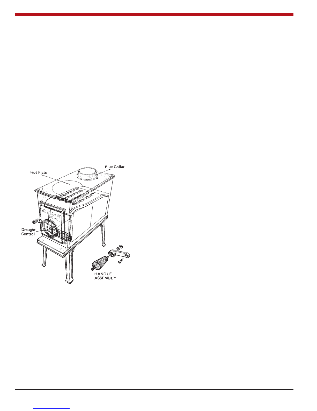
Step 5:
Take the hotplate (WIF 008) and place it in the large
opening on the top. Do not remove the Hot Plate when
the unit is in operation. Remove only for cleaning.
Step 6:
Attach the Spigot, item number 18, in the exploded view
to the hob, item number 16 using the two 1/4” (6mm)
counter sunk screws provided.
Check that all parts are securely fitted before firing the
unit.
The stove is now ready for installation.
Fig.1
CHIMNEY TYPES - CANADA ONLY
The stove must be connected to an Underwriters
Laboratories of Canada Labelled Factory Built 650 C
Chimney, installed in accordance with the manufacturers
instructions or a lined Masonry Chimney, constructed
acceptable to the authority having jurisdiction.
CHIMNEY CONNECTOR
THE CHIMNEY CONNECTOR is a smokepipe used to
connect the 104 MK II Stove to the approved chimney
described above. The CHIMNEY CONNECTOR must be
made of CORROSION RESISTANT STEEL 24 gauge or
heavier (“black or blued” or equivalent treated steel).
SINGLE WALL STOVE PIPE MUST NOT PENETRATE
COMBUSTIBLE WALLS OR CEILINGS.
A 127mm to 153mm (5 to 6 inch) increaser is included in
the Stove kit. When using the 127mm to 153mm ( 5 to 6
inch) increaser, 153mm (6 inch) diameter connector pipe
is used. Be sure to fasten the chimney connectors
together and also to the flue outlet of the stove through
the two holes provided. Use at least two screws for each
joint. Be sure the joints are tight and fully secured.
CHIMNEY CONNECTOR USA ONLY
Connectors should maintain a pitch or rise of at least 1/4”
(6mm) to the foot from the stove to the chimney. It should
be installed so as to avoid sharp turns or other construction features that would create excessive resistance to
the flow of flue gases. It should be securely supported
with joints fastened with sheet-metal screws, rivets, or
other approved means. The entire length of a connector
should be readily accessible for inspection, cleaning and
replacement.
The connector may pass through walls or partitions constructed of combustible materials provided the connector
is either listed for wall pass-through or is routed through a
device listed for wall pass-through and is installed in
accordance with the conditions of the listing, NFPA 211 or
CAN/CSA - B365. Any unexposed metal that is used as
part of a wall pass-through system and is exposed to the
flue gases shall be constructed of stainless steel or other
equivalent material that will resist corrosion, softening, or
cracking from flue gas at temperatures up to 982
o
C
CONNECTING TO MASONRY CHIMNEY
The connector to a masonry chimney must extend
through the wall to the inner face or liner but not
beyond,and must be firmly cemented to masonry.
The connector may pass through walls or partitions constructed of combustible material to a masonry chimney
provided the connector system selected is installed in
accordance with the proper clearances and conditions.
(See figures 2, 3, 4, 5 & 6 pages 3 & 4).
THIMBLES
Thimbles for chimneys or vent connector should be of fire
clay (ASTM C 315, Specifications for Clay Flue Linings)
galvanised steel of minimum thickness of 24 gauge, or
material of equivalent durability. Thimbles should be
installed without damage to the liner. The thimble should
extend through the wall to, but not beyond, the inner face
of the liner and should be firmly cemented to masonry.
Thimbles should be located to provide adequate pitch or
rise of chimney or vent connectors and, where the ceiling
above the appliance is constructed of combustible material, the location of the thimble should provide minimum
clearance required for the connector as specified in
Section under minimum clearances to combustibles.
Insulation material used as part of wall pass-through system should be of non-combustible material and should
have a thermal conductivity of 1.0 Btu.in./ft.F
(4.88kg.cal/hr.m.C) or less. All clearances and thicknesses are minimums; larger clearances and thicknesses are
acceptable. Any material used to close up an opening for
the connector should be of non-combustible material. A
connector to a masonry chimney, except for system 2
(Under heading Chimney Connector Systems, Thimbles
and Clearances), shall extend to piece through the wall
pass-through system and the chimney wall to the inner
face of the flue liner, but not beyond.
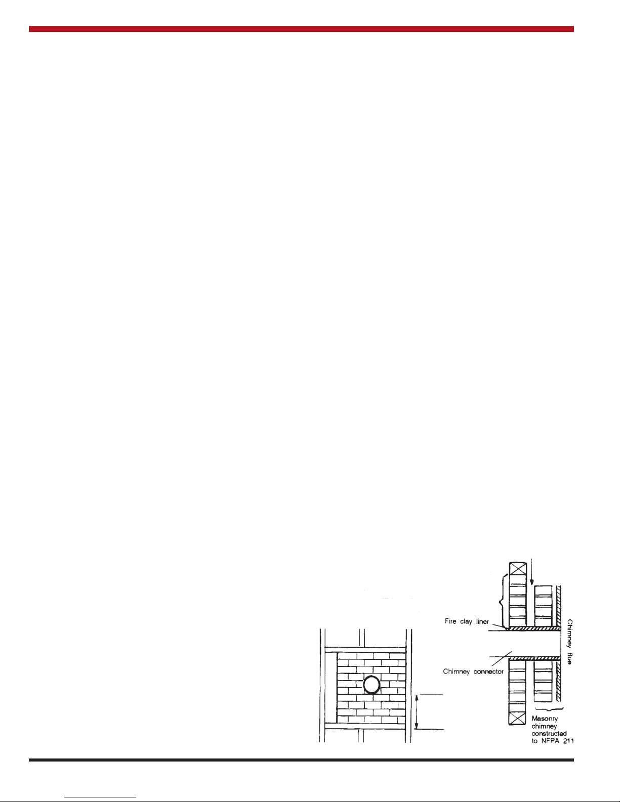
CHIMNEY CONNECTOR SYSTEMS, THIMBLES,
AND CLEARANCES FROM COMBUSTIBLE
WALLS
1. Minimum 3 1/2” (90mm) thick brick masonry wall
framed into combustible wall with a min. of 12”
(305mm) brick separation form clay liner to combustibles. Fire clay liner (ASTM C315 or equiva
lent) min. 5/8” (16mm) wall thickness, should run
from outer surface of brick wall to, but not
beyond, the inner surface of chimney flue liner
and should be firmly cemented in place.
3
Fig.2
Minimum clearance 12” (305mm) of brick
Minimum 12” (305mm)
to combustibles
Minimum chimney clearance
to brick and combustibles 2” (50mm)
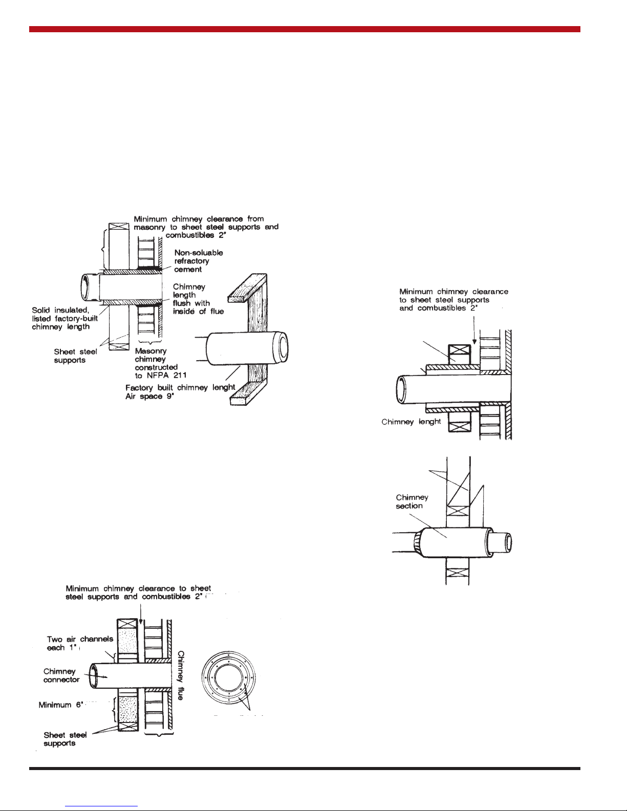
2. Solid insulated listed factory-built chimney length
of the same inside diameter as the chimney
connector and having 1” (25mm) or more of insulation with a min. 9” (229mm) air space between
the outer wall of the chimney length and combustibles. The inner end of the chimney length
shall be flush with the inside of the masonry
chimney flue and shall be sealed to the flue and
to the brick masonry penetration with nonwatersoluble refractory cement. Supports should be
securely fastened to wall surfaces on all sides.
Fasteners between supports and the chimney
length shall not penetrate the chimney liner.
4. Solid insulated listed factory-built chimney length
with an inside diameter 2” (50mm) larger than the
chimney connector and having 1” (25mm) or
more of insulation, serving as a pass-through for
a single wall sheet steel chimney connector of
min. 24 gauge thickness, with a min. 2” (50mm)
air space between the outer wall of chimney section and combustibles. Min. length of chimney
section shall be 12” (305mm). Chimney section
concentric with and spaced 1” (25mm) away from
connector by means of sheet steel support plates
on both ends of chimney section. Opening shall
be covered and chimney section supported on
both sides with sheet steel supports of min. 24
gauge thickness.
Supports should be securely fastened to wall surfaces on
all sides and shall be sized to fit and hold chimney section. Fasteners used to secure chimney sections should
not penetrate chimney flue liner.
3. Sheet steel chimney connector, min. 24 gauge in
thickness, with a ventilated thimble, min 24
gauge in thickness, having two 1” (25mm) air
channels, separated from combustibles by a min.
of 6” (150mm) of glass fibre insulation. Opening
should be covered and thimble supported with a
sheet steel support, min. 24 gauge in thickness.
Supports should be securely fastened to wall surfaces on all sides and should be sized to fit and
hold chimney section. Fasteners used to secure
chimney sections should not penetrate chimney
flue liner.
4
Fig3
Fig.4
Fig.5
Fig.6
(50mm)
(229mm)
minimum
Minimum
clearance 9”
(229mm)
(50mm)
(25mm)
(150mm)
glass fibre insulation
Two ventilated air
channels each 1”
(25mm) constructed of
sheet steel
(50mm)
Minimum clearances 2” (50mm)
1” (25mm)
air space to
chimney
length
Air space 2” (50mm)
 Loading...