

Page 1
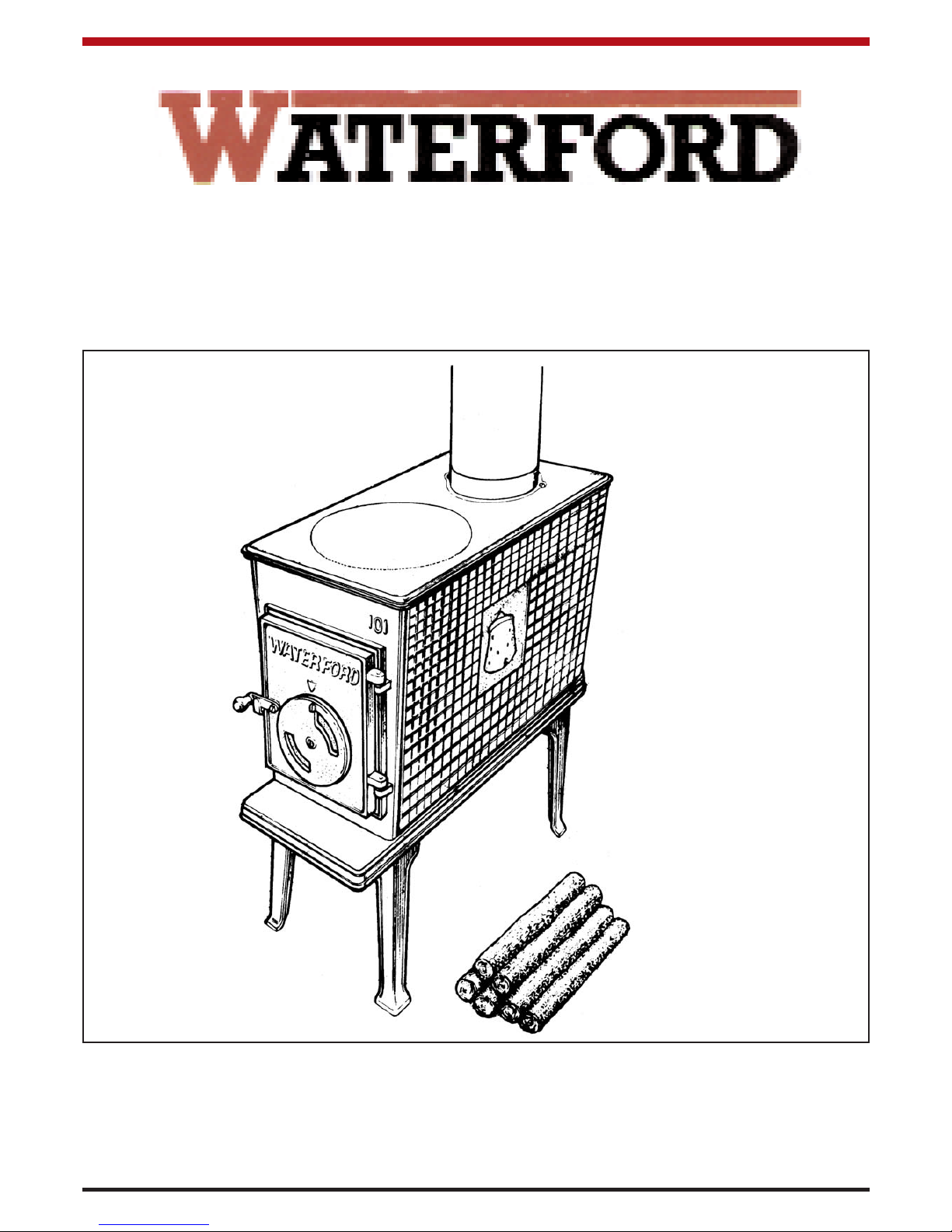
101
WOOD - BURNING STOVE
Do-it-Yourself Stove Assembly. Installation-
Operation-Maintenance
Page 2
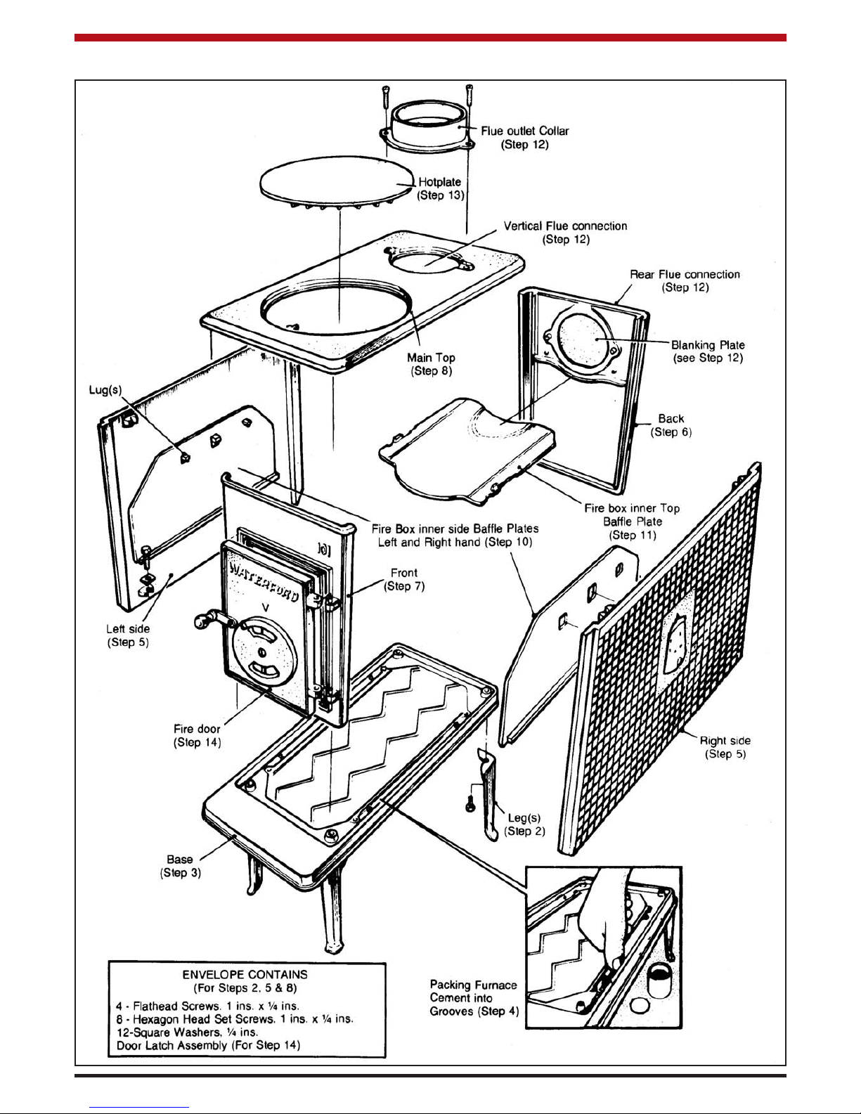
COMPONENTS
2
Page 3

DO-IT-YOURSELF STEP-BY-STEP ASSEMBLY
Sealing to ensure smoke tight joint s is absolutely essential. Do it by applying Furnace Cement firmly - do not
over-use it - into the grooves of the castings, as specified below . Clean hands regularly during application of
Furnace Cement to avoid finger marks on the stove. (There is extra cement for maintenance, flue jointing etc.
- keep the lid shut tight). Handle procelained (V itreous Enamelled) castings with extra care.
S tep 1: Base # WIF-112: Place up side-down on workbench or floor.
S tep 2: Four Legs # WIF-019: Insert the legs in the corner receiving socket s of the base. Secure each in
position with a flathead screw (1ins. x 1/4 ins) and a square washer (1/4 ins.).
S tep 3: S tand the base upright on it s legs.
S tep 4: Use thumb to pack Furnace Cement into the groove around the base.
S tep 5: Sides (Lef t & Right) # WIF-014: Reginalds Tower is embossed on the outside of each side. (Be sure
you position it right way up). Place each side in the cement-filled groove of the base and secure it in position
with hexagon-head set screws (1 ins. x 1/4 ins.) and square washers (1/4 ins.). Do not tighten up fully until
S tep 8 (below) is completed.
S tep 6: Back # WIF-018: Pack furnace cement into the groove on each side of the back. Place the back in
the cement-filled base groove and push firmly into position to ensure that the furnace cement sealing is ef fec tive on both sides of the back. Keep the back in position with a convenient prop. (Note that the back comes
with the rear outlet blanking plate # WIF 010 fitted).
S tep 7: Front # WIF-123: Gently lif t the firedoor # WIF-122 of f the front and place it aside until S tep 14 . Pack
furnace cement into the grooves on each side of the front. Place the front in the cement-filled base groove and
push firmly into position to ensure that the furnace cement sealing is ef fective on both sides of the front.
S tep 8: Main T op # WIF-106: Place the top up side-down on workbench or floor . Pack furnace cement into
the groove around the top. Invert and position top (large opening to front) on top of the body assembly. Fit the
main top to the sides with Hexagon-head set screws (1 ins. x 1/4 ins.) and square washers (1/4 ins.).
S tep 9: T ighten up gently all bolt s at the base of each side, back and front. Relieve the tension by backing
each of f slightly. i.e. a small backturn that will not allow a loosening of the joint s. W ipe away surplus cement
from all joint s.
S tep 10: Two Firebox Inner Side Baffle Plates # WIF-1 17: These baf fle plates are identical. Hang lef t and
right on lugs provided inside the main body assembly.
S tep 1 1: Firebox Inner Top Baffle Plate # WIF-111: Slide the plate over the top of the two inner side baf fle
plates. Push right in so that it locates firmly against the back of the body assembly.
S tep 12: Flue Outlet Collar # WIF-011: For vertical (stovepipe) connection to chimney: screw the flue out let collar into the small opening at back of the main top.
For rear outlet connection to chimney: Remove the rear outlet blanking plate # WIF-010 from the back. Screw
it into the small opening at the back of the main top. Now screw the flue outlet collar to the back.
S tep 13: Hotplate # WIF-008: Place in position in the large opening, front of the main top.
S tep 14: Door Latch Assembly - The door latch and knob assembly are p acked completed in jif fy bag.
Remove the fixing screw and nut. Screw the latch on to the front of fire door then lock the screw in position
with washer and nut provided. Make sure you have free movement of latch. Hang the Fire Door on the lugs
on the front.
ALLOW 24 HOURS BEFORE LIGHTING FOR FURNACE CEMENT TO SET
INSTALLATION
Satisfy yourself that the chimney is of sound construction with the walls and liners free from cracks, loose or
broken material. Remove any accumulation of creosote, soot etc..
Actual placement of the stove - where it will distribute maximum radiant and convected heat - will be deter mined by the availability of a safe system of flue-gas venting.
NEVER INSTALL IN A CLOSED SPACE OR ALCOVE.
There must be a clearance area of 30 inches all round the stove. Protect the floor (if of combustible material)
by using 24 gauge or thicker sheet steel or other suit able material. This floor protection must project at least
18 inches beyond the front, and not less than 12 inches from sides and rear.
Type of connection to the chimney depends on the circumst ances, e.g.:
A. For top or back connection by single steel connectors (stove pipes).
B. By venting into existing fireplace opening.
C. Use of insulated-multiple-wall factory-built connectors.
3
Page 4

W aterford Stanley Lt d.,
Bilberry , W aterford, Ireland.
Telephone: (051) 302300
Facsimile: (051) 302375
A. These connectors should be 5 ins / 6 ins in diameter and crimped into the 5 ins flue outlet collar . Corrosion-
resist ant steel, 24 gauge or heavier, is recommended. (Cheap met al pipes are easily damaged by flue gas
acids). When fitting, ensure that the crimped end faces down in order to prevent condensation etc., run
ning down the out side. All joint s should be made secure with rivet s or screws or by use of an approved
corrugated joint. It is import ant that single-wall connectors be kept 18 ins away from combustible material, be as short and straight as possible incorporating not more than two bends or elbows. It is recommended that horizont al lengths of single wall connectors to a chimney should represent not more than 75%
of the vertical portion. In addition, the pitch or rise in the horizont al section should not be less than 1/4 ins
to the linear foot, thus ensuring that the point of connection to the chimney is higher than the outlet from
the stove.
B. The fireplace opening may be sealed by use of a sheet of non-combustible material cut to receive the con-
nector (stovepipe). The closure plate and connector joint s must be ef fectively sealed so that air can enter
the chimney through the firebox only.
DO NOT CONNECT TO A FLUE SHARED BY ANOTHER APPLIANCE.
C. Factory-built connectors will be found useful in situations where no flue is available or the existing flue is
tot ally unsatisfactory . Clearance limit s from combustible materials are marked on each length of connector and this is a help ful safety guide. Chimneys constructed exclusively of stovepipe must terminate not
less than three feet above the point where it exit s the roof and at least two feet higher than the roof peak
parapet or any p art of the building which is less than ten feet away from the stovepipe exit point.
SPECIAL U.S.A. CODES COMPLIANCE
U.S.A. inst allation must be in full compliance with local building and fire codes. Information regarding these
codes can be obt ained from the Local Building Inspector , Fire Dep artment or Community Of fice. Complete and
exact recommendations are contained in the National Fire Protection Association Publications, NFP A No. 89M,
“Heat Producing Appliance Clearances,” 1971, and NFPA No. 211, Chimneys, Fireplaces and V ent s,” 1972.
Insulated Multiple-W all Factory-Built Connectors/Chimneys are required by NFPA No. 211 to be laboratory-list ed and be inst alled in accordance with the listing and the manufacturer ’s instructions. NFP A No. 211 requires
that a connection to a masonry chimney shall extend through the wall to the inner face of the liner but not
beyond, and that it shall be firmly cemented to the masonry. A thimble may be used to facilit ate removal of the
chimney connector for cleaning, in which case the thimble shall be cemented permanently in place with hightemperature cement.
Chimney connectors are required by NFPA No. 211 to have an elevated pitch or rise in the horizont al portion
of not less than a quarter inch to the linear foot so that the point of connection to the chimney is at a higher
elevation than the end nearest the stove.
OPERATION
1. BEFORE SETTING A FIRE, COVER THE BOTTOM OF THE FIRE CHAMBER EVENLY WITH A TWO
INCH LAYER OF SAND OR WOOD ASH. MAINTAIN THIS TWO INCH LAYER AT ALL TIMES WHILE
THE STOVE IS IN USE.
2. Having made a small fire with p aper and kindling to the front of the fire chamber , place full-length logs
on top. Provide plenty of draf t for a few moment s, then close the firedoor and open the firedoor vent fully.
When well alight, close the vent to the point where you obt ain the rate of burning and heat distribution
required. Season the stove gradually - st art with small, slow-burning fires. A void a big roaring fire
until the stove has been used and seasoned with small fires for several days.
 Loading...