

Page 1
INSTALLATION, AND OPERATION MANUAL
Model: WLF-RO5
5 STAGE
REVERSE OSMOSIS SYSTEM
Water Filter Tree
Page 2
Thank you for purchasing the WLF-RO5 Reverse Osmosis (RO) water purification system
The WLF-RO5 is a 5 stage Reverse Osmosis system designed to reduce high amounts of contaminants found
in municipal drinking water including Sediment, Chlorine Taste and Odor, Copper, TDS, Chromium, Fluoride,
Lead, Mercury, Arsenic, Chromium, Cryptosporidium or Giardia.
Osmosis is achieved by forcing water through a semi permeable membrane allowing only pure water to
pass through. The contaminants concentrate on the other side of the membrane and are eventually
flushed down the drain.
This system has 5 separate treatment segments using 5 differentfilters. A sediment filter, GAC filter, carbon
block, membrane and a post carbon filter.
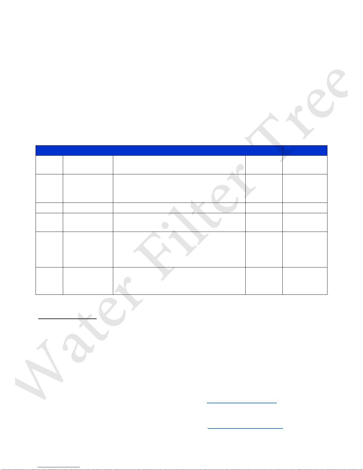
Reverse Osmosis Stages and Filter Models
Stages
Filter Type
Contaminant Reduction
Filter Life
Part
Number
1
Sediment
Filter
(5 micron)
Removes sediment, dirt, silt and rust which
affect the taste and appearance of your
water.
6 Months
WFT-PP01
2
GAC Filter
Reduces Chlorine Taste and Odor
6 Months
WFT-GAC01
3
Carbon Block
(5 Micron)
Reduces a high number of contaminants and
protects the membrane from large particles
6 Months
WFT-CTO1
4
RO Membrane
Reduces a wide range of contaminants such
as Perchlorate, Chromium, Arsenic, Copper
and Lead as well as Cysts, Giardia and
Cryptosporidium
1 Year
WFT-M50
5
In-Line Carbon
Filter
This is a post filter helping to add a balanced
taste to the water. It can also be referred to
as a polishing filter.
6 Months
WFT-P33
System Maintenance
With proper installation and maintenance, this system will provide you with high quality water for years to
come. Please Note: In order for this product to perform as intended, we recommended that you replace
the carbon filters every 6 months or as instructed on this manual. Failure to do so could lead to a buildup
of bacteria known as biofilm.
All of Water Filter Tree products are rigorously tested by an independent laboratory for safety and
reliability.
If you have any questions or concerns, please send an email to info@waterfiltertree.com.
You can also purchase filter replacements via our online store: www.waterfilterjungle.com
Water Filter Tree
Page 3
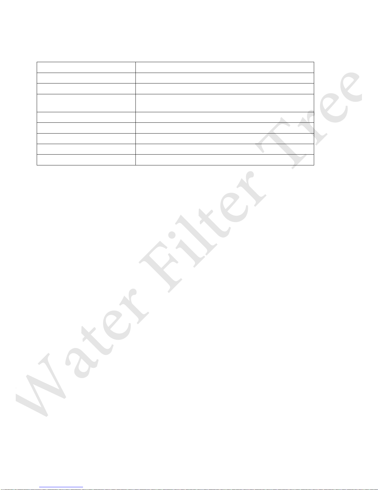
Operational Parameters
Do not use with water that is micro-biologically unsafe or of unknown quality without adequate
disinfection before or after the system. This system is intended to be installed on cold water lines only.
Voltage:
AC110V-DC24V
Maximum Water Generated:
50 Gal or 189 Kg
Pressure Tank Capacity:
3.2 Gal or 12Kg
Operating Temperatures:
Max: 100°F (37.8°C) – Min: 40°F (4.4°C)
Operating Pressure:
Max: 85 psi (6.0 kg/cm2) – Min: 40 psi (2.80 kg/cm2)
pH Parameters:
Maximum 11 - Minimum 2
Desalt Rate:
92-99%
TDS (Total Dissolved Solids)
< 1000 ppm
Turbidity
< 5 NTU
Hardness: Recommended hardness not to exceed 10 grains per gallon, or 170ppm. System will operate
with hardness over 10 grains, but the membrane life may be shortened. The addition of a water softener
may lengthen the membrane life.
Water Pressure: The operating water pressure in your home should be tested over a 24-hour period to
attain the maximum pressure. If the incoming water pressure is above 85 psi a pressure regulator is
recommended and if over 100 psi, then a pressure regulator is required.
Copper Tubing: Reverse Osmosis water should not be run through copper tubing as the purity of the
water will leach copper causing an objectionable taste in the water, and pin holes may form in the
tubing.
Contents of Reverse Osmosis (RO) System
1 Tank 1 Transformer
1 RO Module (complete with filters) 1 Parts Bag
1 Pump - Installed 1 Faucet Bag/Box
1 Manual 1 Filter Housing Wrench
If any of the items are missing please contact Water Filter Tree customer support prior to installing.
Water Filter Tree
Page 4
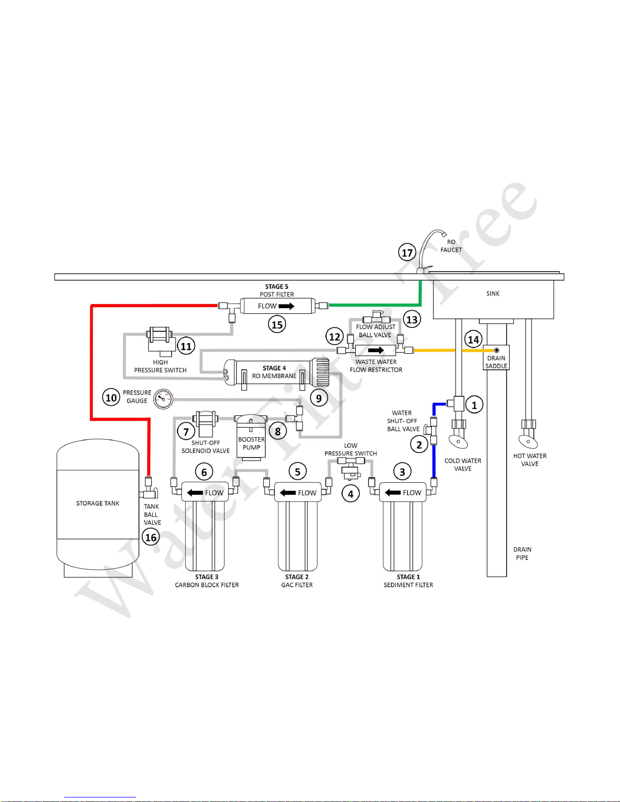
System diagram
Page 5

Parts List
Diagram
Number
Part Name
Part Number
Description
1
Cold Water Valve
WFT-CWV01
Valve that fits onto the cold water supply line. The valve
has a tube that attaches to the inlet side of the RO pre
filter. This is the water source for the RO system.
2
Water Shut-Off Ball
Valve
WFT-
WSOBV02
Shuts off the mains water supply to the system
3
Clear Filter Housing
WFT-CFH03
Housing for the Sediment Filter
4
Low Pressure Switch
WFT-LPS04
Turns off the flow of water when water tank is full,
switching off the pump
5
White Filter Housing
WFT-WHG05
Housing for the GAC Filter
6
White Filter Housing
WFT-WHC06
Housing for the Carbon Block
7
Shut-Off Solenoid
Valve
WFT-SOSV07
When the system isn’t being used it shuts off the mains
water supply
8
Booster Pump
WFT-BP08
(24V-20W) Increases Water Pressure to the RO membrane
9
RO Membrane
WFT-M50
Removes contaminants such as calcium and magnesium
that cause hard water as well as mineral salts, heavy metals
such as lead, agrochemicals, protozoan bacteria, parasites,
industrial chemicals and organic debris
10
Pressure Gauge
WFT-PG10
Measures the system’s operating pressure
11
High Pressure Switch
WFT-HPS11
When the pressure in the tank reaches 2.5Kg/cm², it turns
off the power supply to the pump and the membrane stops
generating water.
12
Wastewater Flow
Restrictor
WFT-WFR12
Maintains the flow rate required to obtain the highest
quality drinking water (based on the gallon capacity of the
membrane). It also helps maintain pressure on the inlet
side of the membrane. Without the flow control very little
drinking water would be produced because all the incoming
tap water would take the path of least resistance and
simply flow down the drain line. The flow control is located
in the RO drain line tubing.
13
Flow Adjust Ball
Valve
WFT-FABV13
Manually adjusts the amount of waste water passing
through the flow restrictor
14
Drain line and Saddle
N/A
This line runs from the Wastewater Flow Restrictor to the
drain. This line is used to dispose of the impurities and
contaminants filtered by the membrane. (Saddle not
included)
15
Post Filter
WFT-P33
After the water leaves the RO storage tank, but before
going to the RO faucet, the product water goes through the
post filter through a carbon block. Any remaining tastes
and odors are removed from the product water by post
filtration
16
Storage Tank
WFT-ST16
The storage tank holds up to 2.5 gallons of water. A bladder
inside the tank keeps water pressurized in the tank when it
is full.
17
Faucet
WFT-FAU01
The RO unit uses its own faucet, which is usually installed
on the kitchen sink. Some areas have plumbing regulations
requiring an air gap faucet, but non-air gap models are
more common
Water Filter Tree
Page 6

Faucet Installation
WARNING: Serious cracking and damage may occur to your sink even if instructions are
followed exactly due to age and the imperfections inherent in natural materials. Instructions
may not apply exactly to your sink. Use caution – sink may be slippery.
Note: Most sinks are pre drilled
with 1 ¼” diameter hole that you
can use for your RO faucet.
1. Locate a suitable place in your sink to install your RO faucet ⑰ and place a piece of masking tape
over where the hole will be drilled. Mark the center of the hole on the tape.
2. Drill a 1/8“pilot hole through the marked center of the desired location of the sink with a variable
speed drill set, on the slowest speed. If drilling through a porcelain sink, use a lubricant liquid soap
to keep the drill bit cool to prevent the sink cracking or chipping.
3. Using the pilot hole as a guide, drill a larger hole using a 1 ¼” diamond tip hole saw on the slowest
speed setting, lubricating as you go, to keep the hole saw cool during drilling.
4. After drilling, sand any sharp edges prior to mounting the faucet.
5. To install the faucet ⑰, feed
the hose (green on the
diagram) through the drilled
hole on the sink.
6. Before installing the faucet,
first attach the Hose
Connector, Anti-Slip Plastic
Ring and the Plastic Sleeve, to
the hose, as shown on the
diagram (Fig.1.2)
7. Slide the fixing plate and the
rubber gasket up the stud until
it reaches the bottom of the
faucet.
8. Then slide the faucet into the
hole, so the stud protrudes on
the underside of the sink.
9. Slide the plastic washer
followed by the lock washer and secure it with the nut provided.
10. Attach the Hose Connector to the end of the stud twisting counter-clockwise until is tightly secured.
Water Filter Tree
Page 7

Cold Water Valve Installation
Caution: Water supply line to the system must be from the cold water supply line only. Hot water will severely
damage your system.
Turn off the cold water supply to the faucet by turning the cold water
valve completely off.
Open cold water sink faucet to relieve pressure.
Attach the 3-way valve to the cold water supply ① making
sure that they are connected to the 3/8” openings.
Caution: Under sink piping can vary, especially in older homes.
If you have a brass 1/2” piping, it will require a different
adaptor. If in doubt you should contact your local plumber.
①
To make a connection, the 3/8” tubes are simply pushed into
the fitting. The unique locking system holds the tube firmly in
place without deforming it or restricting flow.
Cut the 1/4” RO tube supplied that attaches to the inlet side of
the RO pre filter ③ to install the Water Shut-Off Valve ②.
This valve will help switching the supply of water to the RO
system whilst keeping supply to the main sink.
②
Water Filter Tree
Page 8

Drain Saddle Installation
Drain Saddle (Not Supplied) should fit standard 1 ¼” – 1 ½” drain pipes
Caution: If you have a garbage disposal, do not install the drain saddle near it. Installation of the drain saddle must
be either above the garbage disposal, or if a second sink drain is available, install it above the cross bar on the second
drain.
Choose a suitable location on the drain
pipe to drill the RO waste water drain
hole.
Caution: The drain saddle ⑭ must be
mounted at least 1 ½” above the nut of
the P-trap or cross bar from the garbage
disposal to insure proper drainage.
Prior to drilling place a strip of tape on the
chosen location, to avoid the drain pipe
damaging during drilling.
Assemble the drain saddle around the
drain pipe. Using a screw driver tighten
screws evenly and securely on both sides
of the drain saddle.
With the drain saddle secured onto the
drain pipe, use a 1/4” drill bit installed in
your electric drill and insert the drill bit
through the opening in the drain saddle
and drill into the drain pipe.
Caution: In order to prevent damage of to
drain saddle while drilling, it’s is very
important to keep the drill centered.
Insert the 1/4” tube into the opening in
the drain saddle and hand tighten the nut
with a 1/4” wrench.
Important: When inserting the 1/4” pipe
into the drain saddle make sure is not
pushed in right to the end, as this may
prevent the water from draining properly.
Water Filter Tree
Page 9

Main Connections Installation
Diagram
Input
Instructions
Having installed the cold water feed
and the Water Shut-Off Valve ②, you
will now need to connect a 1/4” pipe
between the Water-Shut Off Valve ②
and the Stage 1 Sediment Filter
Housing ③ input shown in Blue (Feed
Water IN).
The Water Shut-Off Valve ② has a
quick connect push fitting and the RO
feed Input has a Screw Fitting. For the
Stage 1 housing Input, unscrew the
cap of the connector and insert the
1/4″ pipe through the cap into the
connector. Screw the cap back on, to
secure.
Next, connect the Faucet input pipe
(already installed, see faucet
installation) to the Green output
located at the Stage 5 Post Filter
(No.15) marked “Tap Faucet OUT”.
For the Stage 5 output, unscrew the
cap of the connector and insert the
1/4″ pipe through the cap into the
connector. Screw the cap back on, to
secure.
Next is the Storage tank connection.
First screw the Tank Ball Valve ⑯
supplied to the Storage Tank until is
tightly secured. Then connect the
remaining 1/4” pipe from to the
Storage Tank to the Stage 5 Post Filter
⑮ Red Output marked “Storage Tank
Out”. Note: Both connectors are
screw fittings. To connect, simply
unscrew the cap of the connector and
insert the 1/4″ pipe through the cap
into the connector. Screw the cap
back on, to secure.
The final connection is the waste
water connection. Simply connect one
hose to the Waste Water Flow
Restrictor. This has a quick connect
tube fitting. And the other end to the
drain saddle (see Drain Saddle
Installation section)
Water Filter Tree
Page 10

Starting up the Unit
Warning: To prevent the possibility of electrical shock, clean up any water under the sink and around the RO
System with a dry cloth.
Note: This unit has a built in Booster Pump, Solenoid Valve, and Pressure Switch and therefore no further
component installation is required.
1. Turn on the cold water valve.
2. Check for any leaks around the machine including the Cold Water supply ①, Water Shut-Off Valve ②,
Tank Ball Valve ⑯, Stage 5 Post Filter ⑮ (Tap Faucet OUT & Storage Tank Out) and Faucet ⑰
3. Once you have checked for leaks, plug the RO unit into the electrical outlet under the sink.
Note: If the RO system does not turn on, check the power outlet. Is possible that this outlet is controlled
by the garbage disposal switch. Flip the switch and see if you can hear the RO pump.
4. Make sure ball valve on the storage tank is open.
5. Open the RO faucet and leave it open until the water begins to drip and then close it. The tank will take
between 2 - 4 hours to fill.
Note: During this time keep on checking for possible leaks.
6. After the tank has filled completely, open the RO faucet and drain the tank.
Note: At this stage the water may come out looking cloudy due to air being trapped in the system. You
may also find carbon particles coming from the polishing filter. This is normal and it will go away after
flushing a couple of tanks of water.
7. Let the tank fill up again and repeat step 6.
6 Month Maintenance
1. First you will need the following consumable part numbers and quantities:
1 x Sediment Filter – Part Number: WFT-PP01
2 x CTO Carbon Block filters (5 Micron) – Part Number/s: WWC105 or WFT-CTO1
2. Close the RO Storage Tank Ball Valve ⑯ and open the faucet ⑰.
3. Turn off the Water Shut-Off Valve ②.
4. Turn off the electrical power.
5. Using the filter wrench provided, open the filter housings ③, ⑤, ⑥ starting with Stage 1, ③ on the
diagram. Remove the housing carefully by turning it clockwise, being careful not to spill the water inside
the housing. Once the housing is removed, discard the water and filter.
6. Repeat the process for filter housings ⑤, ⑥. Stage 2 and Stage 3.
7. Insert the Sediment filter (Part: WFT-PP01) into the Stage 1 housing ③. Make sure the housing O-Ring
is still in place before tightening.
8. Insert the Carbon filter (Part: WWC105) into Stage 1 and Stage 2 housings ⑤, ⑥. Again making sure
Water Filter Tree
Page 11

the O-Ring is still in place before tightening.
9. Once all the filters are installed, make sure there is no water on or around the unit. Dry the surfaces
with a dry cloth. Caution: Failure to do this may result in electric shock, bodily injury, fire, product
failure, or damage
10. Turn on the electrical power.
11. Turn on the Water Shut-Off Valve ②
12. Close the RO faucet and open the RO Storage Tank Ball Valve ⑯. Your RO System is now ready to use.
Yearly Maintenance
Note: If you are disinfecting the system, please see notes in the next page
1. First you will need the following consumable part numbers and quantities:
1 x Sediment Filter – Part Number: WFT-PP01
2 x CTO Carbon Block filters (5 Micron) – Part Number/s: WWC105 or WFT-CTO1
1 x Membrane (Recommended) – Part Number: WFT-M50
1 x Post Filter – Part Number: WFT-P33
2. Close the RO Storage Tank Ball Valve ⑯ and open the faucet ⑰.
3. Turn off the Water Shut-Off Valve ②
4. Turn off the electrical power.
5. Using the filter wrench provided, open the filter housings ③, ⑤, ⑥ starting with Stage 1, ③ on the
diagram. Remove the housing carefully by turning it clockwise, being careful not to spill the water inside the
housing. Once the housing is removed, discard the water and old filter.
6. Repeat the process for filter housings ⑤, ⑥. Stage 2 and Stage 3.
7. Insert the new Sediment filter (Part: WFT-PP01) into the Stage 1 housing ③. Make sure the housing O-Ring
is still in place before tightening.
8. Insert the new Carbon filter (Part: WWC105) into Stage 2 and Stage 3 housings ⑤, ⑥. Again making sure
the O-Ring is still in place before tightening.
9. Remove the Stage 4, RO membrane ⑨ by using the wrench provided. Before you do this, you will need to
disconnect the water inlet tube situated on the cap of the membrane housing. The tube is connected with a
quick release connector. Discard the old membrane and replace with the new one (Part Number: WFTM50).
10. Finally, you will need to replace the Post Filter⑮, Stage 5 (Part Number: WFT-P33). The filters have a
connector attached to either side of the filter. First disconnect the outlet tube from the filter connector that
goes to the faucet (green tube on the RO diagram). This connector uses a screw connection. Do not remove
from faucet side.
Note: There is no need to disconnect the water inlet tubes going into the Post Filter.
Once the tube is disconnected from the outlet connector that is attached to the filter, simply twist the filter
to unscrew the inlet connector attached to the filter. Once the inlet connector is detached from the filter,
unscrew the outlet connector from the filter in the same way. Discard old filter. Attach the connectors to the
new filter in the same order as they were disassembled.
11. Turn on the electrical power.
12. Turn on the Water Shut-Off Valve ②
13. Close the RO faucet and open the RO Storage Tank Ball Valve ⑯. Your RO System is now ready to use.
Water Filter Tree
Page 12

Sanitizing the Equipment
1. If sanitizing the unit, remove all the old filters (Stage 1, 2, 3, 4) from their housings and discard leaving the
inline filter (Stage 5) in place. Please see the Yearly Maintenance Section on how to remove housings and
filters.
2. Screw the housings back on (Stage 2, 3 and 4) to the unit by hand. Don’t use the wrench.
3. Pour 1/2 cup of hydrogen peroxide or common household bleach into the first housing Stage 1 and screw
the housing back on (hand tight).
4. Open the RO Storage Tank Ball Valve and close the faucet ⑯
5. Turn on the Water Shut-Off Valve ②, switch the unit on and let it pressurize for around 2 minutes.
6. Once pressurized, turn the RO faucet on for 1 minute. Close the faucet and wait for 2 minutes.
7. Once the 2 minutes have passed, open the faucet once more time and let it run for 5 minutes.
8. With the faucet still open switch the unit off and turn off the Water Shut-Off Valve ②.
9. Wait until the storage tank is completely drained.
10. Unscrew the housings (Stage 1, 2, 3) and drain the water.
11. Remove the Post Filter⑮, Stage 5 (Part Number: WFT-P33). The filters have a connector attached to either
side of the filter. First disconnect the outlet tube from the filter connector that goes to the faucet (green
tube on the RO diagram). This connector uses a screw connection. Do not remove from faucet side.
Note: There is no need to disconnect the water inlet tubes going into the Post Filter.
Once the tube is disconnected from the outlet connector that is attached to the filter, simply twist the filter
to unscrew the inlet connector attached to the filter. Once the inlet connector is detached from the filter,
unscrew the outlet connector from the filter in the same way. Discard old filter. Attach the connectors to the
new filter in the same order as they were disassembled.
12. Insert the new Sediment filter (Part: WFT-PP01) into the Stage 1 housing ③. Make sure the housing O-Ring
is still in place before tightening.
13. Insert the new Carbon filter (Part: WWC105) into Stage 2 and Stage 3 housings ⑤, ⑥. Again making sure
the O-Ring is still in place before tightening.
14. Insert the new RO membrane ⑨ Stage 4. (Part Number: WFT-M50).
15. Turn on the electrical power.
16. Turn on the Water Shut-Off Valve ②
17. Close the RO faucet and open the RO Storage Tank Ball Valve ⑯.
18. Once the storage tank is full, open the faucet and drain the storage tank. Repeat this 3 times.
19. Your RO System is now ready to use.
Water Filter Tree
Page 13

Checking Air Pressure in the Tank
Note: If you notice a decrease in available water from the RO system, check the air pressure in the storage tank. You
can add air with a bicycle pump using the schrader valve that is located on the bottom of the tank behind a black
plastic cap.
1. Turn off the Water Shut-Off Valve ②, switch the unit off.
2. Turn the faucet on and drain the water in the tank.
3. Once the tank is completely drained (water slows to a trickle) check the air using a pressure gauge.
4. Pressure should read 5-7 PSI.
5. If pressure is low use the bicycle pump to increase the pressure.
Caution: In order for this product to perform as intended, Operation and maintenance and filter
replacement must be carried as scheduled
Warning: To reduce the risk associated with the indigestion of contaminants: Do not use with water that is
microbiologically unsafe or of unknown quality without adequate disinfection before and after the system
For more information about the benefits of RO filtration please visit www.waterfiltertree.com
Please refer to this manual for proper maintenance and operated as specified in this owner’s manual, there
is a risk of exposure to contaminants
Water Filter Tree is a Trademark of Vectornate USA Inc. All Rights reserved.
Customer Service: info@waterfiltertree.com
Water Filter Tree
 Loading...