

WECO
HydroSense Reverse
Osmosis Water Filter
Installation Manual
Water Engineering Corporation
Long Beach, CA U.S.A
1 (888) 675-5187
sales@wecofilters.com
www.wecofilters.com

1
Installation Manual
INTRODUCTION
Congratulations! By choosing WECO Reverse Osmosis (RO) water purification system for your
home, you have not only ensured the highest quality, healthy drinking water, you have also
selected the most efficient and convenient system in the industry.
While the elegant, yet simple, design complements any décor, the aesthetic qualities are only the
beginning. We designed the premier RO system as a highly efficient, easily maintained addition to
every home and business.
The RO System filters multiple substances harmful to humans and pets including, impurities, residual
chlorine, heavy metals, chemicals, and filterable, viruses to name a few, and also removes 96
percent of ions in the water.
Before installing your new RO System, please read the instructions thoroughly and make sure you
have all the necessary tools at hand.
Your new Reverse Osmosis Drinking Water system used a combination of filtration technologies to
reduce unwanted contaminants in a water supply. The following steps combine to give you the
best in clear sparkling drinking water.
Mechanical Filtration – The sediment pre-filter will remove the larger particles such as silt, rust, and
scale. Its 5-micron (equal to 0.0002 inch) nominal rating helps to give maximum life to the RO
membrane and carbon filter.
Activated Carbon Pre-filters- The activated carbon in a pre-filter will remove any chlorine that
may be present in the feed water.
This pre-treatment is also necessary for membrane protection in chlorinated water.
Reverse Osmosis Membrane – The RO membrane is the heart of the filtration system. It is designed
to reduce the dissolved mineral content of the water. Minerals picked up in the environment by
the water are measured as Total Dissolved Solids (TDS). In the reverse osmosis process, dissolved
minerals are separated from the incoming water (feed water) to produce the product water (the
permeate). The excess minerals are rinsed to drain (the reject water). The spiral-wound
construction of the RO membrane provides maximum surface area for water production and is
less susceptible to fouling by particulate matter, turbidity, and colloidal materials.
Inline Carbon Absorption Post-filter- The activated carbon post-filter cartridge contains carbon
particles with a vast network of pores. The tremendous surface area of these pores (typically
800-1,200 square meters per gram of carbon) gives the carbon very good absorption sites for
chlorine as well as other substances that contribute to tasted and odors. The product water from
the membrane and the holding tank passes through the inline carbon post-filter on the way to the
dispensing faucet. The activated carbon post-filter reduces tastes and odors that may pass
through the systems. It adds a final “polish” to the water.
Booster Pump Models – The booster pump consists of the pump, transformer unit, and the tank
shut-off switch. The tank shut-off switch will shut down the pump when the water production is not
necessary, such as when the tank is full, to prevent prematurely burning out the pump. Booster
pumps are used when there is little or no water pressure (below 30 psi is considered very low water
pressure). The booster pump increases and maintains your water pressure at the optimum level for
maximum rejection of total dissolved solids (TDS) and filtered water production.
© 2017 Water Engineering Corporation
Installation Manual
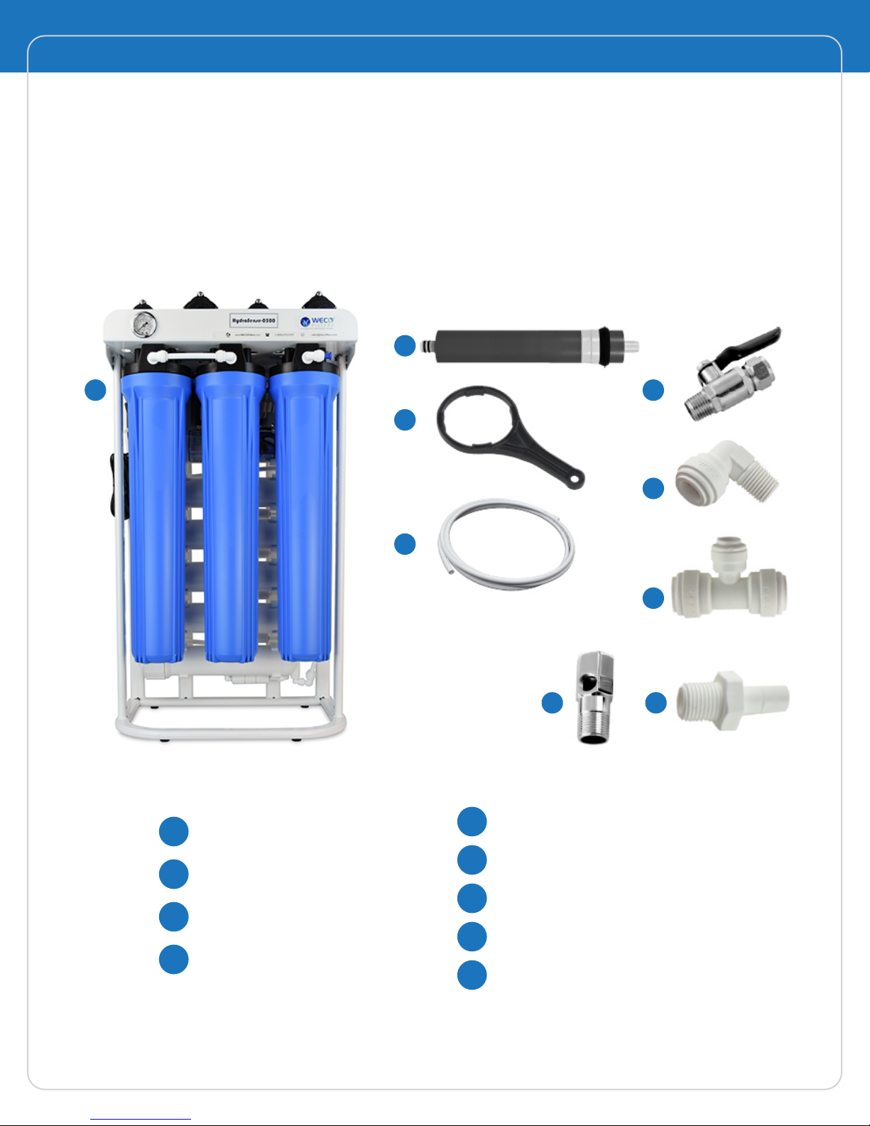
Components List
Your new WECO Reverse Osmosis System should include the following items. If any item is missing,
please contact your supplier, retailer, or any local professional plumbing service. Please take a
few moments to check all following components.
2
2
1
3
4
8 9
Fig. #1
5
6
7
Reverse Osmosis System Unit
1
RO Membrane Filter Cartridge
2
Filetr Housing Wrench
3
Polyethlene Tubing
4
© 2017 Water Engineering Corporation
5
6
7
8
9
Chromed Ball Valve
Male Elbow Fitting Connector
Union Tee Fitting Connector
Chrome Feed Water Adapter
Stem Adapter Fitting
3
Installation Manual
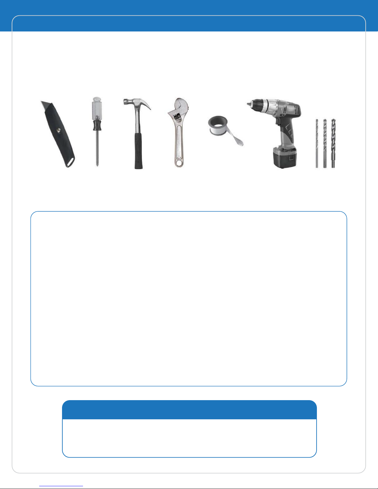
Before Installation
Before you begin, make sure the installation kit and tools are complete and ready to use.
Fig. #2
Tools required for installation: utility knife, Phillips screwdriver, hammer, adjustable
wrench, Teflon seal tape, electric drill, and drill bits (1/8”, 1/4” and 7/16”).
Before you Begin - Important Notes
Important Note: Feed Water Quality - Reverse osmosis drinking water systems are not
intended to be used for the treatment of water that is microbiologically unsafe or of
unknown quality. If the feed water quality is unsafe or unknown, have a sample of the
water tested by a qualified laboratory or agency and implement the necessary measures
to ensure a safe water supply.
Check with Local Codes - Some codes may require installation by a licensad plumber;
check with the local plumbing authority prior to installation.
Air Gap - An Air Gap (not included) should be installed prior to the drain to prevent
backflow of contaminated wastes from the drainpipe.
Drain Connections - Some state orlocal codes may require that the drain saddle be
served by a trap other than the one serving the garbage disposal. Before making a
connection, please check with code authorities.
Do not use water that is microbiologically unsafe or of unknown quality
without adequate disinfection before or after the system.
CAUTION
© 2017 Water Engineering Corporation

Installation Manual
4
Quick Connect EZ Fitting Guide
Your Reverse Osmosis Drinking Water Appliance is outfitted with the new generation of userfriendly
EZ connect push-in fittings. Proper use of the fittings is shown in the diagrams below.
It is important that the tubing selected for use with these connectors be of high quality, exact size
and roundness, and with no surface nicks or scratches. If it is necessary to cut the tubing, use a
plastic tubing cutter or sharp razor knife. Make a clean, square cut.
Should a leak occur at a fitting, the cause is
usually a defective tubing end cut.
To fix:
• Relieve pressure
• Release tubing
• Cut off at least ¼” from end
• Reattach tubing
• Confirm connection is leak free
To Attach Tubing
1
Collet
Cut the tube squarely, and insert tube
into the lock fitting (be sure the lock
fitting is flush for secure insert).
Push tube inward while pushing the
lock fitting outward and insert the
lock pin.
Pull the tube to ensure tube is tightlly
fitted.
Fig. #3
To Release Tubing
Tubing
Push tubing straight in as far as it will go.
2
Tubing is secured in position.
© 2017 Water Engineering Corporation
Fig. #4
Push in collet to release tubing.
To Insert Locking Clip
Optional Blue
Locking clip
slides between
collet and fitting.
Fig. #5
Fig. #6

5
Installation Manual
Component Recognition / Product Overview
6
8
7
5
6
7
23
1
5
4
1st stage - 20” STND White Filter
1
HSG 3/4” ports (Sedim ent Filter)
2nd stage - 20” STND White Filter
2
HSG 3/4” ports ( Carbon Block Filter )
3rd stage - 20” STND White Filter
3
HSG 3/4” ports ( Carbon Block Filter)
4th stage - RO Membrane Housings
4
(100 GPD RO Membrane Element x5 - 500 GPD)
Fig. #7
5
6
7
8
Flow Restrictor
High FlowBooster Pumps
Power Supply (transformer)
Pressure Gauge
© 2017 Water Engineering Corporation

Installation Manual
6
Installation Instructions
Pipe Connection:
CAUTION
The water supply to this reverse osmosis system MUST be from the
COLD water line. Hot water will damage the RO system. Before
installation, be sure to shut off the house’s main water line.
Tapping into the cold water line
1. If the feed water tubing connection is too short, future filter cartridge replacement will be very
difficult. Place the machine in a location convenient for service and installation. Measure the
distance between the feed water valve point to the RO system inlet point, then cut the RED PE
(polyethylene) tube to measured length. An additional PE tube is included in the installation kit.
2. Locate the self-piercing feed water valve, turn off cold water supply under the sink, and open
faucet to relieve water pressure.
To install on (soft) copper tubing supply line:
• Turn the handle of the feed water saddle value counter clockwise (outward) until the lance does
not protrude from the gasket. It may have to be pushed in.
• Assemble the feed water saddle on the tubing.
• To pierce the tubing, turn the valve handle fully in the clockwise direction until the copper tube is
pierced and the valve is closed.
To install on (hard) steel, galvanized, or CPVC tubing supply line.
• The supply line should now be drained. Use a battery-powered or properly grounded drill to avoid
shock hazard.
• Drill a 3/16” hole in the supply line; (do not drill through the opposite wall)/
• Turn the handle to expose the lance no more than 3/16” beyond the rubber gasket.
• Place the body of the valve over the hole so that the lance fits into the hole.
• Assemble and tighten the brass screw.
• Turn the valve handle clockwise (inward) until firmly seated and the valve is closed.
3. With the feed water saddle valve closed, open the sink faucet and the water supply and
allow the water to run for a few minutes to flush out any debris caused by the installation.
Close the faucet and check the feed water saddle valve for leaks.
© 2017 Water Engineering Corporation

7
Installation Manual
Power Supply Installation
Locate the power outlet under the sink or near
the RO system unit. Make sure the power cord is
long enough to reach the power outlet; if not,
contact a licensed electrician to install a power
outlet.
RO Membrane Cartridge Installation
1. Release the tubing from the end cap of the membrane housing
2. Unscrew the end cap from the membrane housing on the appliance, and insert the
membrane as illustrated below.
Fig. #8
3. The O-rings on the product water tube of the membrane MUST FULLY SEAT in the membrane
housing for proper operation. Make sure that the brine seal on the membrane seals with no
gaps or wrinkles inside the membrane housing.
4. Once the membrane is installed, replace the end cap and reconnect the tubing.
To ensure that all preservatives are flushed from the system before use, DO NOT use the first
two tankfuls of water produced by the system.
Step 1
Step 3
Step 2
Step 4
Turning counter clockwise
to unscrew the end cap
O-rings on the product water tube
Insert the RO membrane cartridge
this direction
Fig. #9

Installation Manual
Maintenance and Cartridge replacement
Important Note: The RO System functions directionally. Please do not randomly fill or drain water or
interchange the cartridge from left to right.
The need for filter replacement varies with water quality and usage. Replace cartridges on a regular
basis to ensure the highest quality water and extend the life of the system.
1. Before replacing filter cartridges, turn off water, power, and tank ball valve, then turn the RO
faucet (black lever) up to let the water flow out completely.
2. Using filter housing wrench to turn ( unscrew ) the filter housing clockwise to open the filter
housing.
3. Discard of recycle the used cartridge. Replace the new filter cartridge and screw the filter
housing back on the cap. Turn the filter housing counter clockwise until tight and seal.
8
4. Repeat previous steps on the next filter.
5. Turn on the water supply and check for leaks.
6. After replacing all filter catridge stages, flush
the system with one tankful of water before
use.
7. Replace filter cartridge regularly to ensure
the quality of drinking water and extend the
life of the system.
Reverse Osmosis Systems Replacement Cartridges
System
HydroSense-0400
HydroSense-0500
HydroSense-0500DI
HydroSense-0500GAC
HydroSense-0500UV
HydroSense-0500GAC-CAL-UV
Stage 1
Filter
PD-5-20
Polydepth
PD-5-20
Polydepth
PD-5-20
Polydepth
PD-5-20
Polydepth
PD-5-20
Polydepth
PD-5-20
Polydepth
Stage 2
Filter
EP-20
Carbon Block
EP-20
Carbon Block
EP-20
Carbon Block
EP-20
Carbon Block
EP-20
Carbon Block
EP-20
Carbon Block
twist-off to remove twist-on to lock it
Fig. #10
Stage 3
Filter
CBC-20
Carbon Block
CBC-20
Carbon Block
CBC-20
Carbon Block
CBC-20
Carbon Block
CBC-20
Carbon Block
CBC-20
Carbon Block
Stage 4
Filter
TW - 1812-
100
TW - 1812-
100
TW - 1812-
100
TW - 1812-
100
TW - 1812-
100
TW - 1812-
100
Stage 5
Filter
GS - 210DI
GS - 215RO
GL10SE4P
GS -
10CAL/RO
Stage 6
Filter
GL10SE4P
© 2017 Water Engineering Corporation

9
System Performance and Operating Limits
Production Rate GPD (m3/d) 50 GPD
Stabilized Salt Rejection 98%
Minimum Salt Rejection 98%
Feed Water TDS 2000 ppm Max
Feed Water Temperature 40 ~ 113 °F
Feed Water Pressure 40 ~ 85 psi
Feed Water pH 5 ~ 10
Installation Manual
Feed Water Hardness < 10 grains per gallon
Feed Water Iron < 0.1 ppm
Feed Water Manganese < 0.05 ppm
1. Production flow and salt rejection based on the folllowing test condition: 250 ppm softened tapwater, 77 °F (25 °C), 50 psig
and 15% recovery
2. Permeate flow rates for individual elements may vary +/- 20%
3. Booster Pump models may significantly increase production and TDS reduction rates, average pressure increased by 60 psi.
_
_
_
Troubleshooting
RO System does NOT start up
Power cord not plugged in, Power outage
Transformer burned out
Insufficient water (water cut off) and inlet pressures
Booster pump malfunction
Post filter cartridges are clogged
High pressure switch failure
Low pressure switch failure
Check and connect power
Check the transformer input voltage/overload burned out
Check the inlet water pressure
Replace Booster pump
Check if post filter cartridge is clogging the water flow
Replace high pressure switch
Replace low pressure switch
Insufficient Output RO Water
Insufficient water pressure coming out of booster pump
RO membrane filter element got clogged
Insufficient water input
Stage 1,2 or 3 filter cartridge is clogged
No or Little Decrease in TDS Value in Product Water
RO membrane connector O-RING deformed with leakage
RO membrane ruptured/aperture enlarged
Replace booster pump
Replace RO membrane
Check if the Stage 1,2 or 3 filter cartridge is clogged
Check if the Stage 1,2 or 3 filter cartridge is clogged/replace
Replace O-RING
Replace RO membrane element cartridge
© 2017 Water Engineering Corporation

Installation Manual
System NOT Treating Water After Replacing Filter Cartridge
10
Air in the tubing (AIR)
Pressurized Motor Continues to Restart Frequently
Outlet check valve is not blocking water completely
Leakage in the tubing
Booster Pump Motor Burned Out
Abnormal frequent startup and overheat
Pressurized Motor Junction Leakage
Motor triangular diaphragm rupture
Motor Does NOT Pump Up the Pressure
Air in the motor
Insufficient water input
Release the air in the tubing
Replace check valve
Lock tight/replace tubing
Replace booster pump
Replace booster pump
Release the air
Check if water supply and post filters cartridge are clogged
RO Water Smells or Tastes Strange
Inline active carbon is saturated
Intermittent usage, water ceases flowing
Stage 1,2 or 3 filter cartridge Junction Leakage
Filter housing not locking tightly
Filter housing o-ring deformed
Transformer Burning Smell
Power input specification error/burned out
Replace inline activated carbon filter cartridge (polished filter)
Drain tank water/replace inline active carbon cartridge
Lock each filter housing ( canister ) tightly
Replace housing o-ring
Check if power input complies with standard specs
© 2017 Water Engineering Corporation

11
Installation Manual
This page is intentionally left blank

WECO HydroSense
WECO
Reverse Osmosis
Water Filter
Installation Manual
www.wecofilters.com
Water Engineering Corporation
Long Beach, CA U.S.A
1 (888) 675-5187
sales@wecofilters.com
 Loading...