


Waterdrop WD-G3-W, WD-G3-B, WD-G3-G Installation Manual


Find the installation video
Search “Waterdrop G3 RO installation” on
Register 1-year manufacturer warranty*
Visit warranty.waterdroplter.com
and enter the product serial number:
Any questions, please contact Waterdrop
by phone: 1-888-352-3558 Mon-Fri 8:00 AM-5:00 PM (PST) or
by email: service@waterdroplter.com
Performance Data Sheet
Standards Substance Inf. Average
TDS 750 mg/L 92.90% 62 mg/L 187 mg/L ≥75%
Tested and Certied by NSF International in Model WD-G3-W
against NSF/ANSI Standard 58 for the reduction of the claims
specied on the Performance Data Sheet, and to NSF/ANSI
372 (≤0.25% lead).
NSF Specified
Challenge Concentration
750 mg/L ± 20%NSF58
This device complies with part 15 of the FCC Rules. Operation is
subject to the following two conditions: (1) This device may not cause
harmful interference, and (2) this device must accept any interference
received, including interference that may cause undesired operation.
Any Changes or modications not expressly approved by the party
responsible for compliance could void the user's authority to operate
the equipment.
Ave. %
Reduction
Average Product
Water Concentration
Max Permissible
Product Water
Concentration
NSF Reduction
Requirements
NSF Test
Report
J-00356525
* Please refer to Limited Product Warranty on Page 19


Contents
Installation Instructions
Before Installation ···············································1
Parts List ·························································2
Product Introduction ·············································3
Installation Tips ···················································4
Installation Steps ················································5
Step 1: Install the Feed Water Adapter
Step 2: Install the RO Faucet
Step 3: Install the Drain Saddle
Step 4: Position the RO System Housing
Step 5: Connect Tubing
Step 6: Connect Power Cord
Step 7: Install the Filters
Step 8: Start up the System
·········································6
······································7
·············································8
············································9
·············································9
·········································10
·································5
·······························7
Owner’s Manual
Display and Operation ···········································12
Section 1: TDS Display
Section 2: Filter Life Reminder
Section 3: Filter Replacement Guide
Section 4: Automatic Flushing
·············································12
·······································12
··································14
······································15
ion 5: Malfunction Display
Sect
······································15
System Maintenance ···········································16
Troubleshooting ·················································17
Limited Product Warranty ·······································19

Installation Instructions
Before Installation
Inspect the Package
Open the box and take out the system housing, all the components and connect
ttings. Inspect them according to the parts list to ensure nothing is left out or
damaged during shipping. If there are any parts cracked or broken, please do not
proceed with the installation and contact Waterdrop by phone: 1-888-352-3558
Mon-Fri 8:00 AM-5:00 PM (PST) or by email: service@waterdroplter.com. Identify
and get familiar with all components for quick installation.
Required Tools:
• Variable speed drill
• Drill bit: 1/4” (for the waste line), 1⅜” (for faucet hole)
• Adjustable wrench, pliers
• Screwdriver
• Utility knife or scissors
• Flashlight
• Towel
Specications
To achieve the optimal performance, it is highly recommended to use the system
within the operational parameters.
Model
RO System Size (L*W
Feed Water Pressure
Feed Water Temperature
Feed Water Requirement
Daily Production Rate
Power Specication
NOTE:
• The Daily Production Rate is measured under 30 PSI dynamic feed water
pressure and 77 °F water temperature.
H)
*
WD-G3-W / WD-G3-B / WD-G3-G
18.06” * 5.68” * 17.76”
14.5-87 PSI / 0.1-0.6 MPa
41-100 °F / 5–38 °C
Municipal Tap Water
400 GPD
Input 110~120V AC
Output 24V DC
1
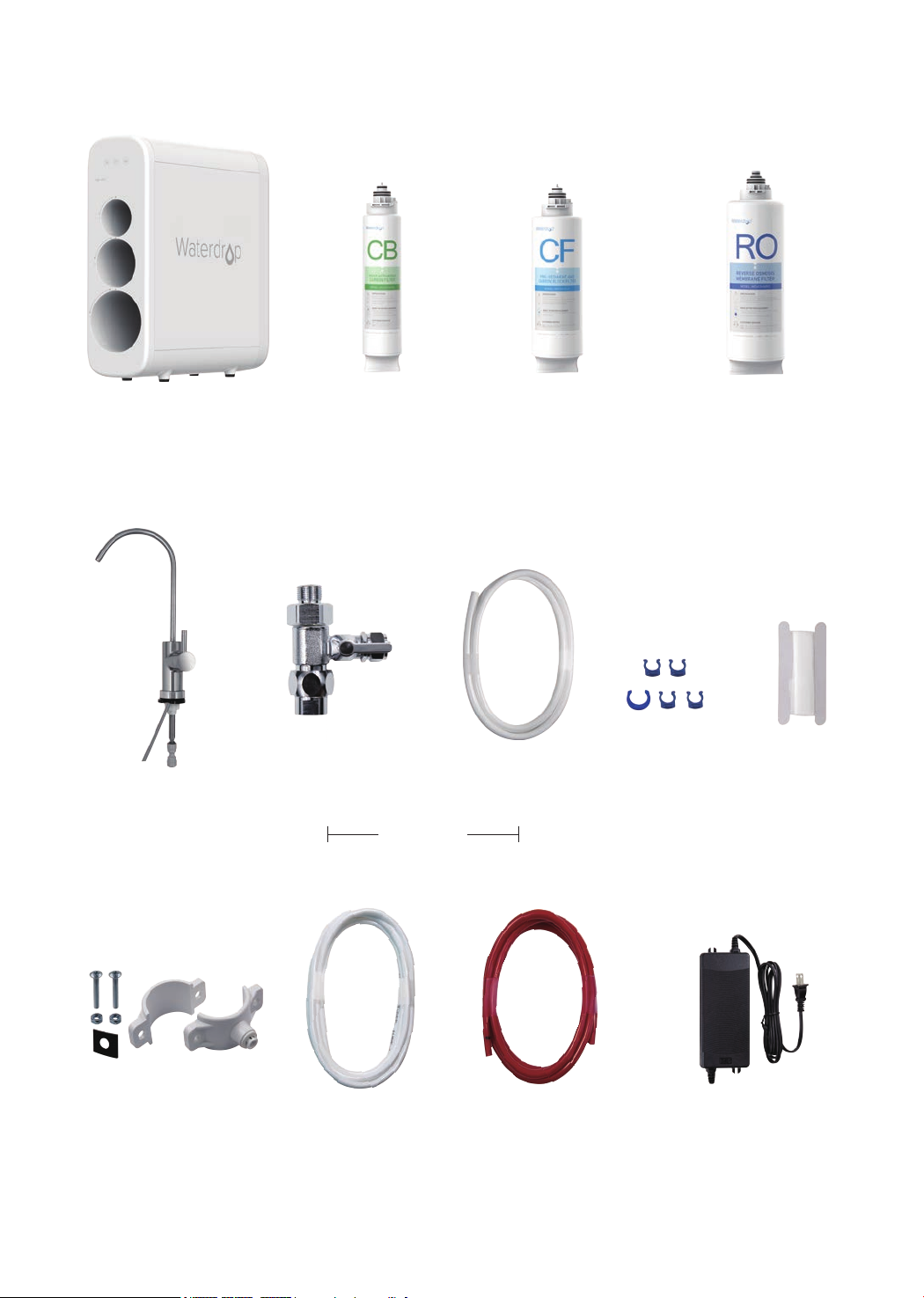
Parts List
System Housing
X 1 Set
RO Faucet
X 1 Set
Activated Carbon Filter
(CB: WD-G3-N3CB)
X 1
Feed Water Adapter
3/8”-1/2”
X 1 Set
Preinstalled
Pre-sediment and
Carbon Block Filter
(CF: WD-G3-N1CF)
X 1
White 3/8” PE Tubing Lock Clip
X 60” X 5
Reverse Osmosis
(RO: WD-G3-N2RO)
Membrane Filter
X 1
Teon Tape
X 1
X 1 Set
White 1/4” PE Tubing
X 60” X 60”
Red 1/4” PE Tubing
2
Power AdapterDrain Saddle 1/4”
X 1 Set
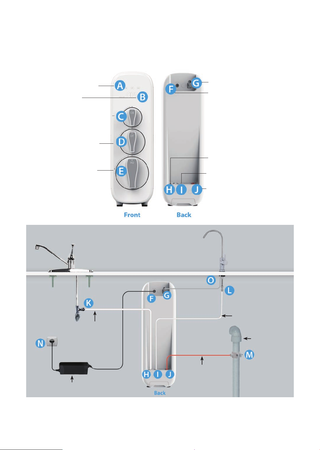
Product Introduction
The brief introduction of various parts and sample connections are presented as
follows. Please identify and get familiar with these parts and connection points for
a smooth installation.
Filter Life Indicators
A:
Display Screen
B:
Activated Carbon Filter
C:
(CB)
Pre-sediment and
D:
Carbon Block Filter (CF)
Reverse Osmosis
E:
Membrane Filter (RO)
“FAUCET” Connector
G:
“POWER” Port
F:
“INPUT” Water Port
H:
“FILTERED” Water Port
I:
“WASTE” Water Port
J:
Sample Connection
Input Water Tubing
3/8"PE Tube
Power Adapter
→
K
H, From Feed Water Adapter to “INPUT” Water Port
L→I, From Faucet Quick-Connect Fitting to “FILTERED” Water Port
Filtered Water Tubing
1/4" PE Tube
Drain Pipe
Waste Water Tubing
1/4" PE Tube
M→J, From Drain Saddle to “WASTE” Water Port
O→G, From Faucet Power Cord to “FAUCET” Connector
→
F
N, From “POWER” Port to Power Socket
3
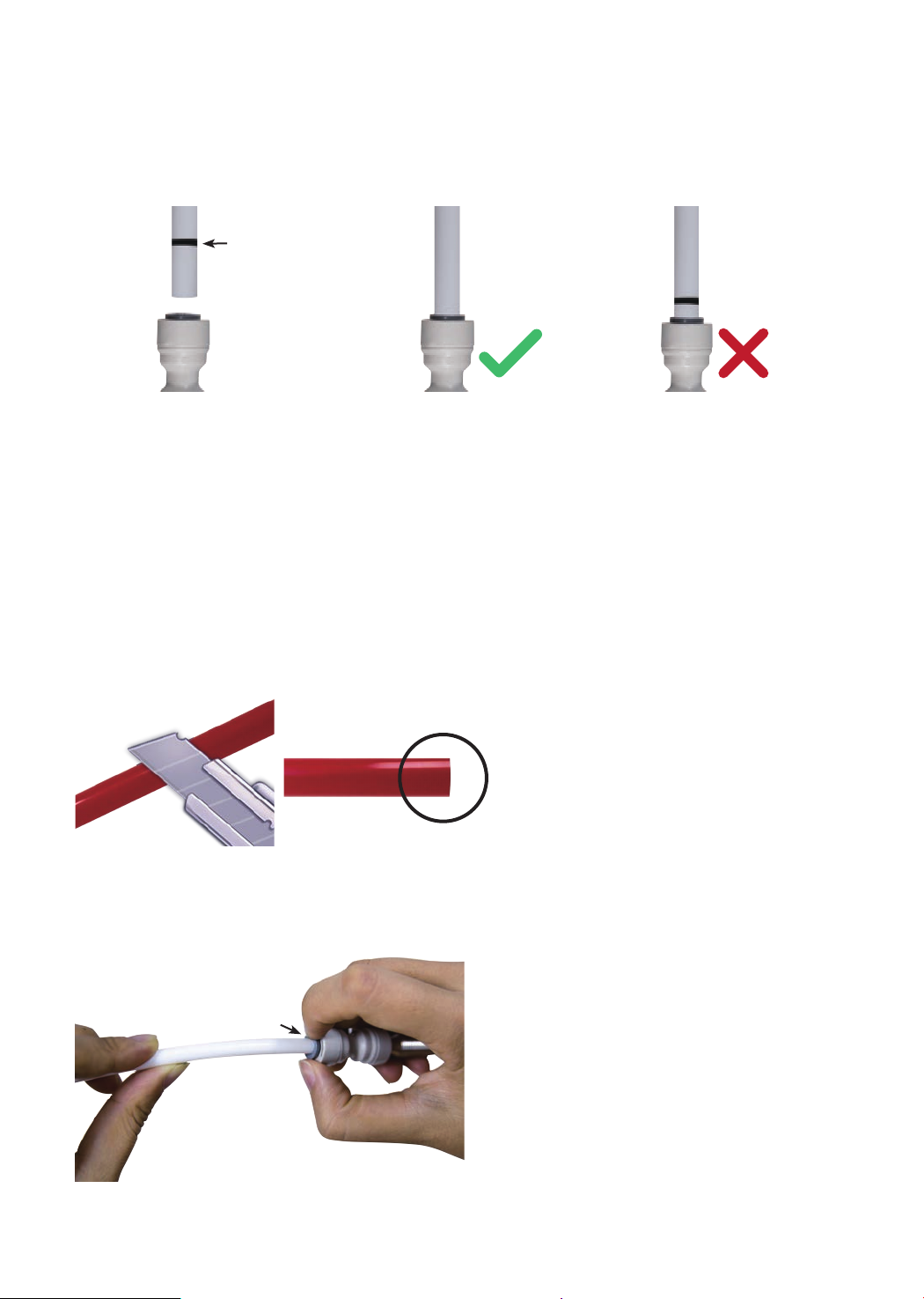
Installation Tips
How to Use the Quick-Connect Fittings
Mark for
Full Insert
Figure 1
To connect:
NOTE: There is an existing mark (Figure 1) at the end of the tubing for you to
conrm if the tubing is fully inserted into the tting.
• Push the tubing into the tting until you reach the mark on the tubing.
NOTE: If the tubing is not fully inserted, no seal will be created and leakage will
occur.
• When the tubing is fully inserted, put the blue lock clip on the tting. It will lock
the tubing in place and prevent it from falling off.
Figure 2
Press
Figure 3
Cut Cleanly
and Squarely
NOTE: If the tubing is too long,
cut it to a suitable length with a
sharp utility knife or scissors. Cut
the tubing squarely and cleanly
(Figure 2). Make sure the tubing
is fully inserted (about 0.8”).
To disconnect:
• Remove the blue lock clip from the
tting;
• Use your thumb and index nger
to press down the lock sleeve. Use
your other hand to pull out the tube
from the tting (Figure 3).
NOTE: Please do not pull out the
tubing directly. This will damage the
tting and cause leakage.
4