

Water Depot Deluxe Series Owner's Manual
By Water Depot
DELUXE SERIES
OWNER’S MANUAL
FOR ALL DELUXE WATER SOFTENERS
THIS MANUAL IS TO BE LEFT WITH THE OWNER OF THE EQUIPMENT FOR REFERENCE AND
PURPOSES AND TECHNICAL GUIDANCE. IT IS STRONGLY RECOMMENDED THAT QUALIFIED
DEALER SERVICE PERSONNEL BE CONTACTED IN THE EVENT OF AN UNKNOWN INTERRUPTION
OF SERVICE OR APPARENT PRODUCT MALFUNCTION. AN ANNUAL PREVENTATIVE MAINTENANCE
INSPECTION BY A WATER PROFESSIONAL IS RECOMMENDED TO ENSURE TROUBLE-FREE AND
CONTINUOUS OPERATION.
www.waterdepotinc.com

TABLE OF CONTENTS
Control Valve Specifications 2
Control Valve Function and Cycles of Operation 3
General Instructions 7
System Setup 8
Setting Options Table 11
Bypass Valve 12
Installation 13
Installer Settings 15
Normal Display Settings 16
General Information 18
Start Up Instructions 19
Drawings and Part Numbers
MR Front Cover and Drive Assembly 20
WS1MR Drive Cap, Pistons and Spacer Stack 21
Replacement Parts 22
Installation Fittings Assemblies 26
WS1 Identification Figure 27
Troubleshooting 28
FOR INFORMATION COMMON TO ALL 1” CONTROL VALVES REFER TO THE WS1 DRAWINGS AND
SERVICE MANUAL
PRE-INSTALLATION INSTRUCTIONS
This unit has a control valve which enables the setting of not only the length of each regeneration cycle but also the
order in which cycles (steps of regeneration) occur. The following pages instruct how to choose the unit‟s sequence
of cycles, cycle times, exchange capacity, and gallon capacity/regeneration time.
THE DEALER…
1. Read this page, GENERAL INSTRUCTIONS, INSTALLER SETTINGS, NORMAL DISPLAY SETTINGS.
2. Read the CYCLE VALVE FUNCTION AND CYCLES OF OPERATION.
3. Complete the SYSTEM SETUP.
THE INSTALLER…
1. Read Bypass Valve page.
2. Read GENERAL INSTRUCTIONS, NORMAL DISPLAY SETTINGS.
3. Be sure CYCLE VALVE FUNCTION AND CYCLES OF OPERATION and SYSTEM SETUP are done
before leaving for installation.
4. Follow INSTALLATION instructions, INSTALLER SETTINGS, TIME OF DAY.
5. Follow START UP INSTRUCTIONS.
1
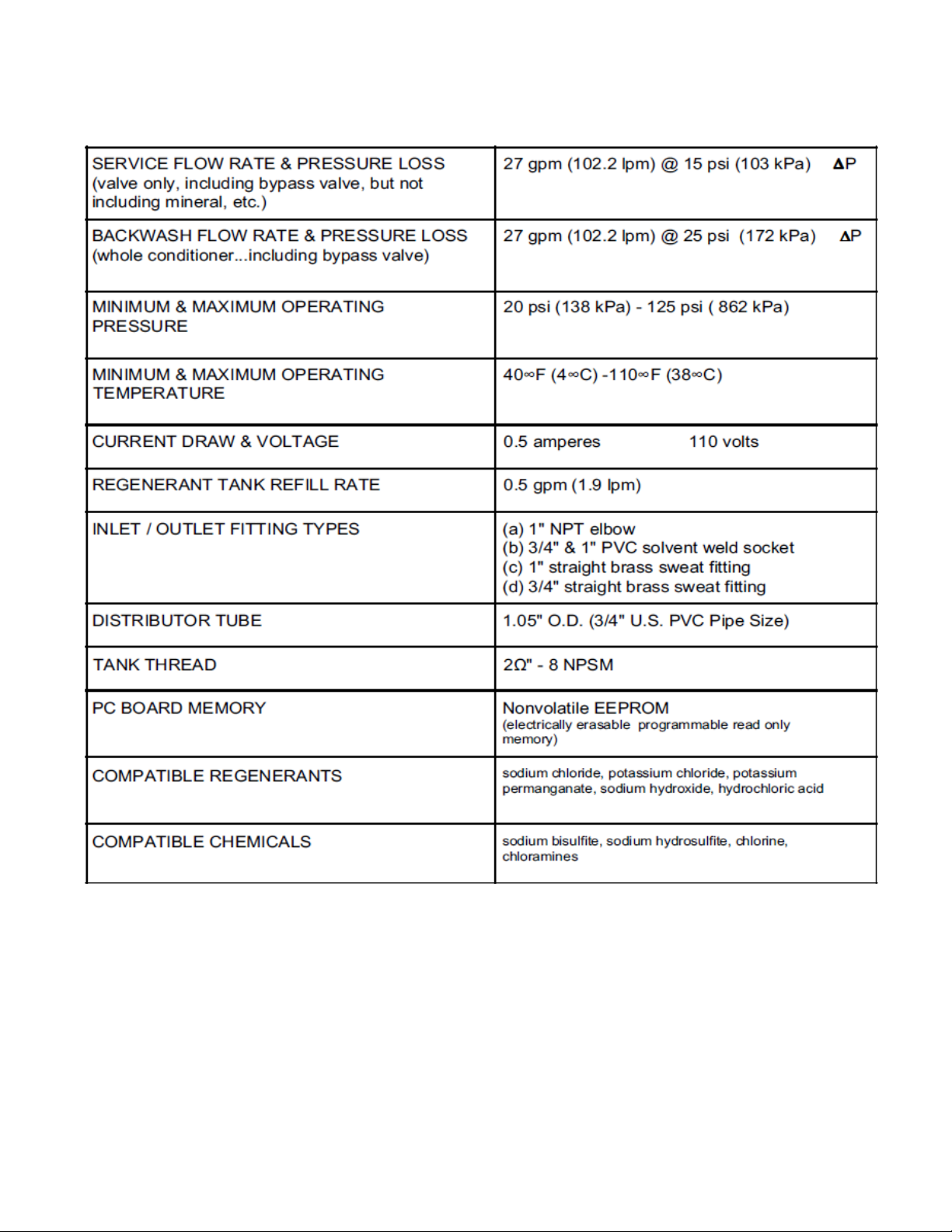
CONTROL VALVE SPECIFICATIONS
2

CONTROL VALVE FUNCTION AND CYCLES OF OPERATION
WS1MR
Downflow Regenerant
Refill After Rinse
1st Cycle Backwash
2nd Cycle Regenerate
3rd Cycle Second
Backwash*
4th Cycle Rinse
5th Cycle Fill/Dissolve
6th Cycle Service
WS1MR
Downflow Regenerant
Prefill
1st Cycle Fill
2nd Cycle Service
3rd Cycle Backwash
4th Cycle Regenerate
5th Cycle Second
Backwash*
6th Cycle Rinse
7th Cycle Service
WS1MR
Upflow Regenerant
Refill After Rinse
1st Cycle Regenerate
2nd Cycle Backwash
3rd Cycle Rinse
4th Cycle Fill/Dissolve
5th Cycle Service
WS1MR
Upflow Regenerant
Prefill
1st Cycle Fill
2nd Cycle Service
3rd Cycle Regenerate
4th Cycle Backwash
5th Cycle Rinse
6th Cycle Service
This glass filled Noryl¹ (or equivalent) fully automatic control valve is designed as the primary control center to direct
and regulate all cycles of a water softener or filter. When the WS1MR control valve is manufactured as a softener,
the control valve can be ordered to perform downflow or upflow regeneration. The WS1.25MR control valve is only
available in downflow regeneration. When the WS1MR or WS1.25MR control valve is set up as a filter, the control
valve can be set to perform downflow regeneration or simply backwash. The control valve can be set to regenerate
on demand (consumption of a predetermined amount of water) and/or as a time clock (passage of a particular
number of days). The control valve can be set so that a softener can meet the Water Quality Association (WQA)
Standard S100 or NSF/ANSI Standard 44 efficiency rating.
It is not recommended to change control valves from downflow to upflow brining or vice versa in the field.
The valve bodies for downflow and upflow are unique to the regeneration type and should not be
interchanged. A mismatch of valve body and regeneration piston will result in hard water bypass during
service.
The control valve is compatible with a variety of regenerants and resin cleaners. The control valve is capable of
routing the flow of water in the necessary paths to regenerate or backwash water treatment systems. The injector
regulates the flow of brine or other regenerants. The control valve regulates the flow rates for backwashing, rinsing,
and the replenishing of treated water into a regenerant tank, when applicable.
The control valve uses no traditional fasteners (e.g. screws); instead clips, threaded caps and nuts and snap type
latches are used. Caps and nuts only need to be firmly hand tightened because radial seals are used. Tools
required to service the valve include one small blade screw driver, one large blade screw driver, pliers and a pair of
hands. A plastic wrench is available which eliminates the need for screwdrivers and pliers. Disassembly for
servicing takes much less time than com parable products currently on the market. Control valve installation is
made easy because the distributor tube can be cut ½” above to ½” below the top of tank thread. The distributor tube
is held in place by an o-ring seal and the control valve also has a bayonet lock feature for upper distributor baskets.
The AC adapter power pack comes with a 15 foot power cord and is designed for use with the control valve. The
AC adapter power pack is for dry location use only. The control valve remembers all settings for two hours if the
power goes out. After two hours, the only item that needs to be reset is the time of day; all other values are
permanently stored in the non-volatile memory. The control valve does not need batteries.
The control valve‟s unique design and electronics allow the OEM to select:
1. a pre or post fill option with up or down flow and adjust the length of the cycles; or
2. a pre or post fill option, select a program code that has a preset cycle order/value and adjustable fill cycle.
Tables 1 and 2 show examples when the valve is set up as a softener or a filter.
* Second Backwash is optional
1
Noryl is a trademark of General Electric.
3
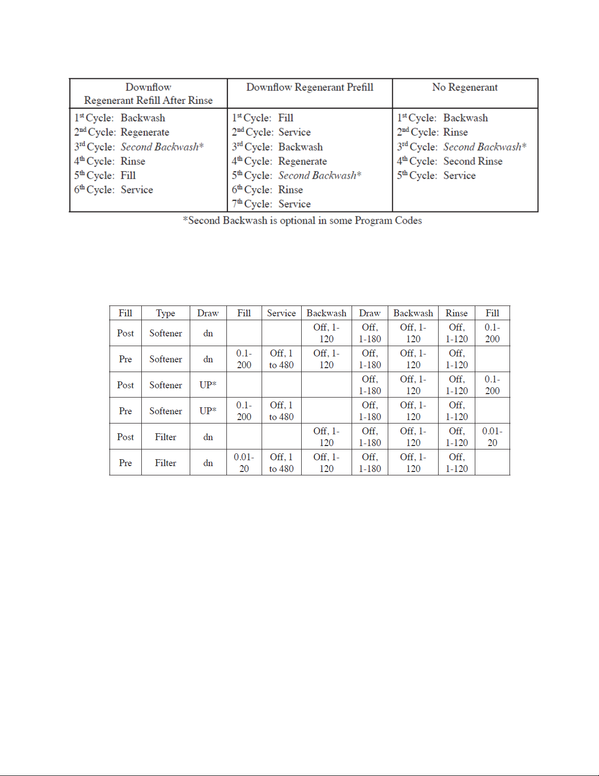
Table 2
Regeneration Cycles Filtering
Table 3
Fill values are pounds of salt if softening is selected and gallons if filtering is selected. All other values are in minutes.
ADJUSTABLE CYCLES
Table 3 shows the order and cycle times for the adjustable cycles.
PRESET PROGRAM CODES
A variety of preset program codes are available. Softener program codes refill in pounds of salt and filter program
codes refill in gallons. Tables 4, 5, 6 and 7 show the length of the cycles when different program codes are
selected. The OEM has the option of having the regenerant refill after the rinse cycle or have the regenerant prefill
before regeneration. If the OEM chooses to have the regenerant prefill before regeneration, the prefill starts four
hours before the regeneration time set. During the 4-hour period in which the brine is being made, treated water is
still available. For example: regeneration time = 2:00 am, prefill option selected, downflow softener. Fill occurs at
10:00 p.m., start of backwash cycle occurs at 2:00 a.m.
4
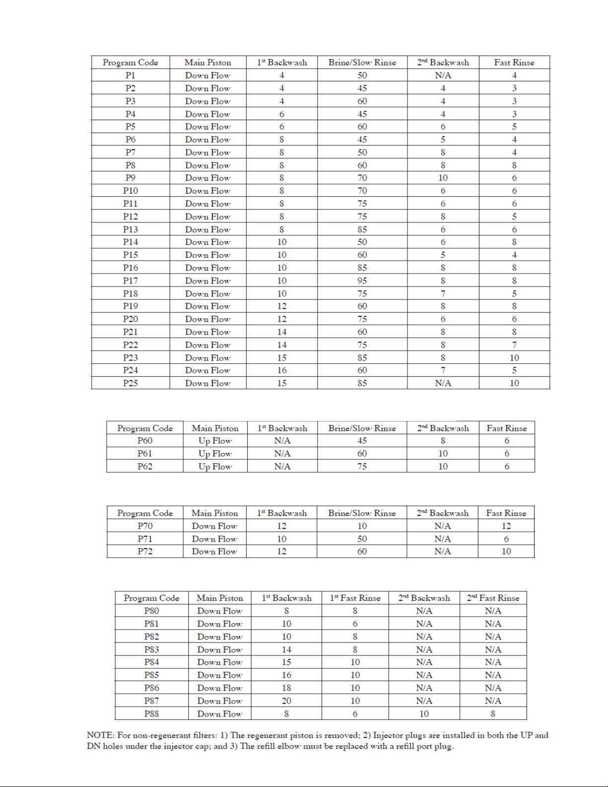
Table 4
Down Flow Softener Program Codes
Table 5
Up Flow Softener Program Codes
Table 6
Regenerating Filter Program Codes
Table 7
Non-Regenerating Filter Program Codes
5

The control valve with a water meter can be set for Demand Initiated Regeneration (DIR) only, Time Clock
operation only or DIR and Time Clock whichever comes first, depending upon what settings are selected for Day
Override and Gallon Capacity.2 See Table 8.
If a control valve does not contain a meter, the valve can only act as a time clock, and day override should be set to
any number and gallon capacity should be set to off.
For DIR Softeners, there are two options for setting the Gallons Capacity. The Gallons Capacity is automatically
calculated if set to AUTO. Reserve Capacity is automatically estimated based on water usage if AUTO is used. The
other option is to set the Gallons Capacity to a specific number. If a specific number is set, reserve capacity is zero,
unless the value is manually set (i.e. the manufacturer intentionally sets the gallon capacity number below the
calculated capacity of the system).
The control valve can also be set to regenerate immediately or at the next regeneration time by changing the
Regeneration Time Option. There are three choices for settings:
1. “NORMAL” means regeneration will occur at the preset regeneration time.
2. “on 0” means regeneration will occur when the gallons capacity reaches zero.
3. “NORMAL” and “on 0” means the regeneration will occur at the preset regeneration time unless the gallons
capacity reaches zero. If the gallons capacity reaches zero the regeneration will begin 10 minutes after no water
usage.
The user can initiate manual regeneration. The user has the option to request the manual regeneration at the
delayed regeneration time or to have the regeneration occur immediately:
1. Pressing and releasing the REGEN button. “Regen Today” will flash on the display and the regeneration will
occur at the delayed regeneration time. The user can cancel the request by pressing and releasing the REGEN
button. This method of manually initiating regeneration is not allowed when the system is set to “on 0,” i.e.
immediately regenerate when the gallon capacity reaches zero.
2. Pressing and holding the REGEN button for approximately 3 seconds will immediately start the regeneration. The
user cannot cancel this request, except by resetting the control by pressing NEXT and REGEN buttons
simultaneously for 3 seconds.
A unique feature of this control valve is the ability to display actual water usage for the last 63 days. The values are
initially stored as “----”. This means the value is unknown. As days pass values are stored as “0” for no flow or the
actual number of gallons. The counting of the gallons starts at the regeneration time. If no regeneration time can be
set (i.e. when the valve is set for immediate regeneration) the counting of gallons starts at 12 a.m. Day 1 is
yesterday, day 2 the day before yesterday, etc. As new values are added the oldest history disappears.
Another unique feature is that the valve automatically calculates a reserve capacity when set up as a softener with
“Gallons Capacity” set to “AUTO” and the “Regeneration Time Option” set to “Normal” or “Normal + on 0”. The
actual reserve capacity is compared to the gallons capacity remaining immediately prior to the preset regeneration
time. A regeneration will occur if the actual reserve capacity is less than the gallons capacity remaining. The actual
reserve capacity is calculated by using the estimated reserve capacity and adjusting it up or down for actual usage.
The estimated reserve capacity for a given day of the week is the maximum value stored for the last three non-trivial
water usages (i.e. more than 20 gallons/day) in seven day intervals.
² See Installer Display Settings Step 3I, OEM System Setup Step 7S for explanations of Day Override and Gallon
Capacity.
³ Day Override and Gallon Capacity cannot both be set to “oFF” at the same time.
6

GENERAL INSTRUCTIONS
The control valve offers multiple procedures that allow the valve to be modified to suit the needs of the installation.
These procedures are:
System Setup
Installer Settings
Normal Display Settings
Diagnostics
Valve History
These procedures can be accessed in any order. Details on each of the procedures are provided on the following
pages.
At the discretion of the manufacturer, the field technician can access all settings. To “lock out” access to diagnostic
and valve history displays and modifications to settings except hardness, day override, time of regeneration and
time of day by anyone but the manufacturer, press ▼, NEXT, ▲, CLOCK in sequence after settings are made. To
“unlock”, so other displays can be viewed and changes can be made, press ▼, NEXT, ▲, and CLOCK in sequence.
When in operation normal user displays such as time of day, gallons remaining or days remaining before
regeneration, current flow rate or total gallons used are shown. When stepping through a procedure, if no buttons
are pressed within five minutes the display returns to a normal user display. Any changes made prior to the five
minute time out are incorporated.
To quickly exit Installer Display Settings, Diagnostics or Valve History press CLOCK. Any changes made prior to the
exit are incorporated.
Sometimes it is desirable to have the valve initiate and complete two regenerations within 24 hours and then return
to the preset regeneration procedure. It is possible to do a double regeneration if the control valve is set to
“NORMAL” or “NORMAL + on 0” in OEM System Setup. To do a double regeneration:
Press the “REGEN” button once. REGEN TODAY will flash on the display.
Press and hold the “REGEN” button for three seconds until the valve regeneration initiates.
Once the valve has completed the immediate regeneration, the valve will regenerate one more time at the preset
regeneration time.
7
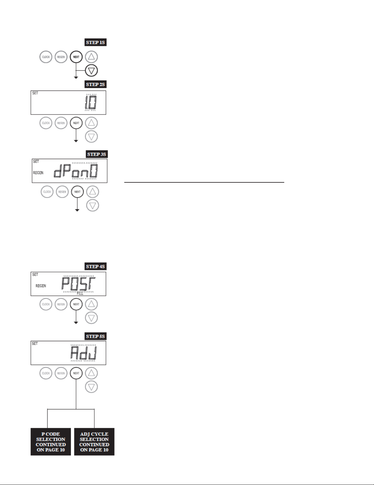
SYSTEM SETUP
STEP 1S – Press NEXT and ▼ buttons simultaneously for 3 seconds. If screen in
step 2S does not appear in 5 seconds the lock on the valve is activated. To unlock
press ▼, NEXT, ▲, and CLOCK in sequence, then press NEXT and ▼
simultaneously for 3 seconds.
STEP 2S – Use the ▲ or ▼ buttons to select 1.0 for WS1MR or 1.25 for the
WS1.25MR. Press NEXT to go to step 3S.
STEP 3S
STEP 3S – Allows selection of one of the following using the ▲ or ▼ buttons:
• an outside signal to initiate a regeneration;
• an outside signal to prevent or delay a regeneration.
Selecting the use of an outside signal to initiate a regeneration:
Selection only matters if a connection is made to the two pin connector labeled DP
SWITCH located on the printed circuit board. Following is an explanation of the
options:
Off - Feature not used. dPon0 - If the dP switch is closed for an accumulative time of 2
minutes a regeneration will occur immediately.
dPdEL - If the dP switch is closed for an accumulative time of 2 minutes a
regeneration will occur at the scheduled regeneration time.
HoLd - If the dP switch is closed a regeneration will be prevented from occurring.
Press NEXT to go to Step 4S.
STEP 4S
STEP 4S – Set Refill option using ▲ or ▼ buttons:
• “PoST” to refill the brine tank after the final rinse; or
• “PrE” to refill the brine tank four hours before the regeneration time set.
Press NEXT to go to Step 5S.
STEP 5S
STEP 5S – Set method for regeneration cycles by using the ▲ or ▼ buttons:
• “Adj” allows manual setting of regeneration cycle times; or
• Choose a P Code with fixed regeneration cycle sequences and times.
Press NEXT.
P CODE ADJ CYCLE
ON PAGE 10 ON PAGE 10
8S
8
Range (Grains)
Increment
5.0 - 50.0 x1000
500
50.0 - 200.0 x1000
2,000
200.0 - 500.0 x1000
5,000
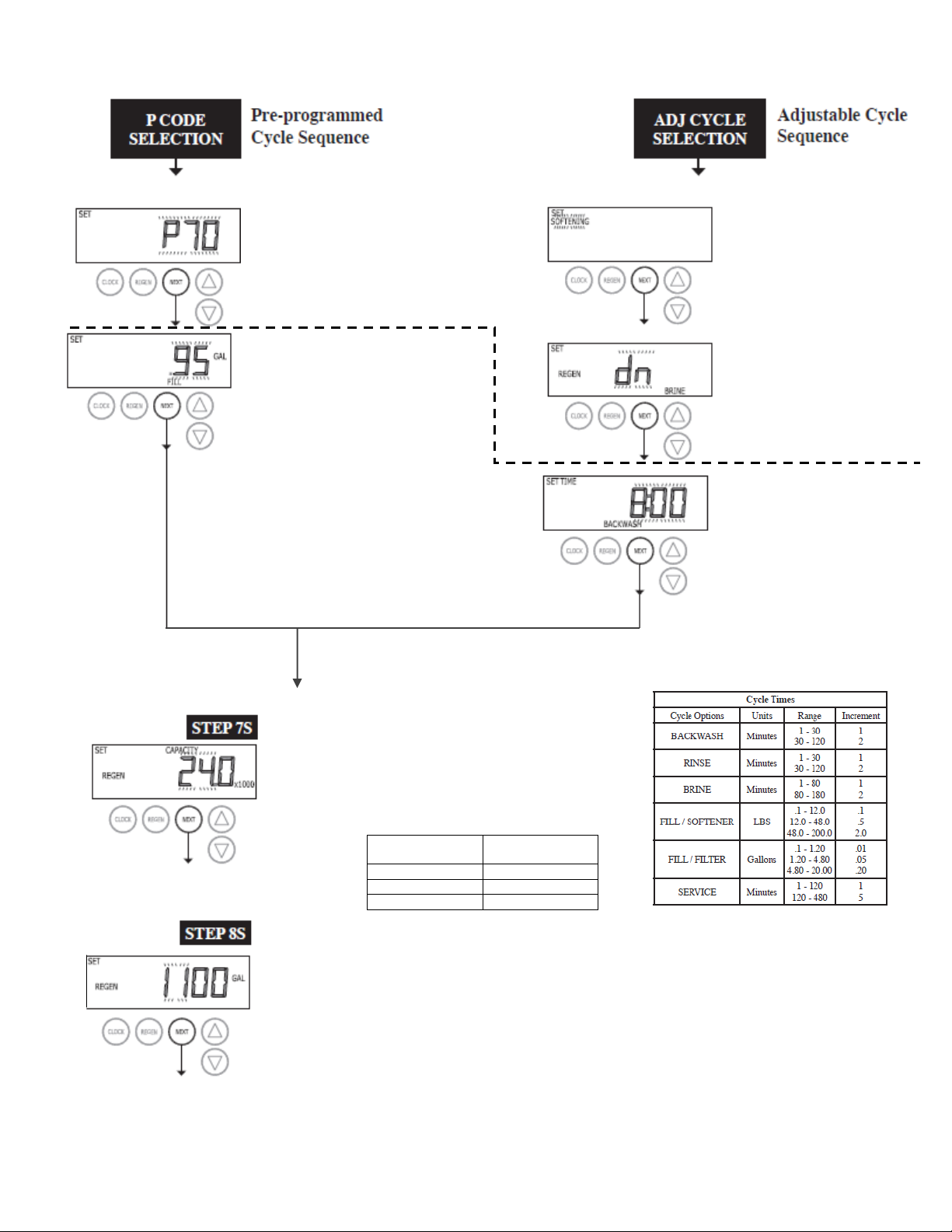
Adj1
Select between
SOFTENING or FILTTHE
Adj2
Set upflow or downflow
regeneration on a 1” control.
This screen will not display if
the unit is set up as a1.25”
or filter valve.
Adj3
Set cycle times. OFF will be
an option in all cycles.
Press NEXT to go to Step
7S
Select between
SOFTENING or FILTTHE
P-Code 1
Selecting pre-set programs. If the unit
is set to 1.25, P60 - P69 will not be
available.
P-Code 2
Set pounds of salt or gallons of
fill. Ranges and increments should
be as shown in Cycle Times table,
but can not be set to OFF.
P1 - P69 = lb (unit measure)
P70 - P79 = Gal (unit measure)
P80 - P99 = No Screen
Press NEXT to go to Step 7S
STEP 7S
System ionic capacity. Enter the ion exchange capacity
in grains of hardness as calcium carbonate for the system
based on test data using ▲or▼buttons. This screen is
not available except when configured P1 - P69 or an Adj
softener.
Press NEXT to go to Step 8S. Press REGEN to return
to the previous step.
STEP 8S - Set Gallons Capacity using ▲or▼buttons:
• “AUTO” (reserve capacity automatically estimated and gallons capacity automatically
calculated from grains capacity and water hardness);
• “oFF” (regeneration based on day override); or
• number of gallons (20 to 250,000).
Note: OFF will not be an option if days override is not set. Auto is not an option on a filter or P70 P88. See Setting Options Table for more details.
Press NEXT to go to Step 9S. Press REGEN to return to previous step.
9
 Loading...