

WaterCop WPACT12V Owner's Manual And Installation Manual
Owner’s Manual and Installation Guide
The proven leader in household leak protection: WaterCop® is there when you’re not.

Table of Contents System Description
System Description ................................ 2
System Components............................... 2
General Safety Information ......................... 4
How the System Works ............................ 4
Operating the WaterCop® Pro ...................... 4
WaterCop® Pro Specifications ...................... 4
FCC Information ................................... 5
System Quick Reference Setting and Status.......... 5
Limited Warranty .................................. 6
To Power and Program Wireless Sensors
Powering Wireless Sensors......................... 6
Programming Hardwired Sensor Probes ............. 6
Programming Wireless Sensors ..................... 7
To Remove Sensors................................ 7
Pre-Installation Testing of WaterCop® Pro
Wiring Instructions ................................. 7
Water Control Panel ............................... 7
Installation of Sensor Probes........................ 8
Manually Testing the Valve and Wireless Sensors
Manually Test the Valve ............................ 8
Manually Test the Wireless Sensors ................. 8
Troubleshooting ................................... 9
Installation of Wireless Sensor ...................... 9
The WaterCop® Pro System is designed to detect leaks
in your plumbing system at predetermined locations, and
automatically shut o the water supply to help eectively
reduce the chances of major water damage associated
with a leak.
WaterCop® Pro (WPKxx or WPACT12Vxx) systems must
be installed indoors. For installations requiring outdoor
valve shut-o, the WaterCop® Pro Outdoor (WPKxxW or
WPACT12VxxW) system should be used. These optional
systems have an outdoor rated cable (NOT DIRECT
BURIAL) and are designated with part numbers ending
in “W”. The Water Control Panel MUST always be placed
indoors. Contact us if you have any questions about the
placement of your WaterCop® Pro.
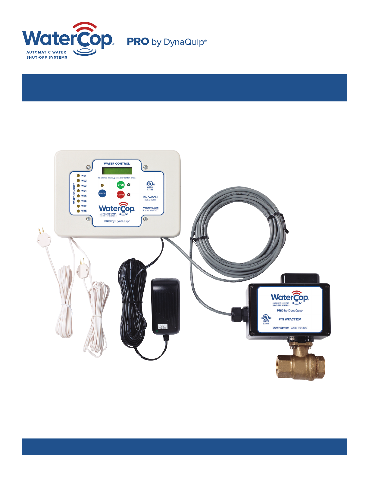
Check the contents of the carton with the products listed
on the carton label. The shipping package should contain
the following:
• 1 each WaterCop® Pro Water Control Panel with 20'
Power Adapter
• 1 each WaterCop® Pro Actuator with attached cable to
connect to Water Control Panel
• 1 Owner’s Manual
You will also need the correct size WaterCop®-ready ball
valve (sold separately).
Read instructions before any installation is attempted. All
sections of this Instruction Manual and accompanying
Quick Start Guide should be read and completely
understood.
Placement of Wireless Sensors .................... 9
Wireless Sensor Battery Life . . . . . . . . . . . . . . . . . . . . . . . 10
Installation Procedure: Indoor vs. Outdoor
Selection of Valve Installation Sites.................. 10
Review the Location and Type of Main Supply Line ... 10
Additional Parts Requirements ...................... 11
Compression Fittings .............................. 11
Solder Fittings..................................... 12
Electrical Connection .............................. 12
Emergency Procedures............................ 12
Warnings and Precautions......................... 12
2
System Components
Water Control Panel – Standard: LCD display with back
light provides instant feedback of sensor alarm and trouble
conditions as well as open/close status of the brass valve.
On/O push buttons for local control of the brass valve.
Audible alarm sounds when any sensor detects flooding.
Internal mounting bracket mounts to standard wall boxes
for aesthetics and cord management. AC/DC power
converter with 20' cord included. Cabling of 25', 50' or 75'
is included to connect the WaterCop® Pro Actuator to the
WaterCop® Control Panel.
Water Control Panel – Hardwired: Accommodates
up to 8 zones for hardwired flood sensor probes (sold
separately). AC/DC power converter with 20' cord
included. There is a 25', 50' or 75' cable included
to connect to the WaterCop® Pro Actuator. As with
all sensitive electric equipment, the use of surge
protection is highly recommended.
Hardwired Sensor Probes: 10' white cord with single
sensor probe. WaterCop® Pro sensors are easily secured
to the floor using the mounting holes. Hardwired sensors
provide the same feedback to the Water Control Panel
as the WaterCop® Pro wireless sensors. Use hardwired
sensor probes for convenience, or if conditions prevent
wireless communication.
Water Control Panel – Standard
WATER CONTROL
To silence alarm, press any button once.
OPEN
MODE
CLOSE
PN/WPC
Made in the USA
watercop.com
St. Clair, MO 63077
Lead-Free Brass Valve: Full port, NSF/ANSI 372
approved, lead-free, brass, 125 psi cold water, designed
for placement on incoming water main.
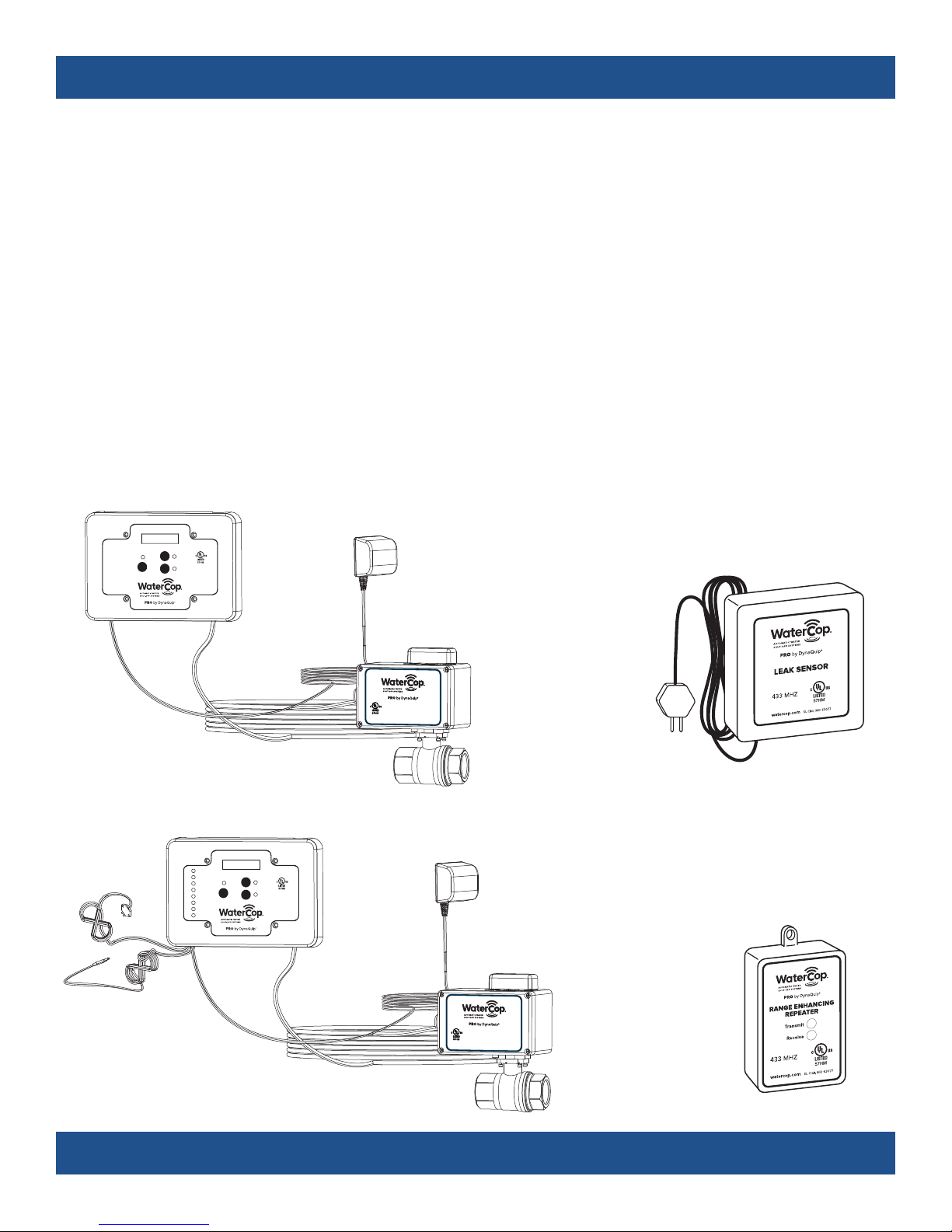
Wireless Sensor: Power using 2 AA alkaline batteries
or optional AC/DC power converter (sold separately).
Batteries will provide backup power to sensors upon
loss of electricity. Wireless sensors are addressable and
supervised for conditions such as water detection, sensor
short/open, and low/dead battery. 10' sensor probe cord
allows for optimal sensor placement. Wireless sensors
can support single or dual sensor probes. Each Water
Control Panel can support up to 45 wireless sensors.
Range Enhancing Repeater: Enhances the transmission
range of the wireless sensors. Plugs into any standard
wall outlet. Receives and re-transmits sensor signals from
outlying sensors to WaterCop® Pro Water Control Panel.
Wireless Sensor
Transmitter
Variable Length
Indoor-Rated Cable
(outdoor-rated optional)
Water Control Panel – Hardwired
WATER CONTROL
WS1
To silence alarm, press any button once.
WS2
OPEN
WS3
WS4
MODE
CLOSE
WS5
WS6
WIRED SENSORS
WS7
WS8
Variable Length
Indoor-Rated Cable
(outdoor-rated optional)
PN/WPCH
Made in the USA
watercop.com
St. Clair, MO 63077
P/N WPACT12VP/N WPACT12V
watercop.com
St. Clair, MO 63077
WaterCop® Pro Actuator
Brass Valve
(sold separately)
P/N WPACT12VP/N WPACT12V
watercop.com
St. Clair, MO 63077
WaterCop® Pro Actuator
(sold separately)
Brass Valve
Probe
DynaQuip Controls, Inc. St. Clair, MO
www.watercop.com
Range Enhancing
Repeater

CAUTION!
It is strongly recommended that eye protection be
worn while servicing the system. Failure to do so
could result in personal injury.
DO NOT USE EXTENSION CORDS. KEEP FINGERS
AND OBJECTS AWAY FROM THE VALVE.
GENERAL SAFETY
INFORMATION
Do not apply electrical power to the unit unless the
unit is fully assembled. Failure to do so could result in
personal injury and/or damage to the unit. Disconnect
power source before working on or servicing the unit.
Failure to do so could result in personal injury.
How the System Works
Flood sensors constantly monitor their selected areas
for accumulating moisture. When a leak is detected,
a sensor will send a radio frequency signal (RF) to the
WaterCop® Pro Water Control Panel, instructing it to
close the Brass Valve, shutting o the water supply to
the home. The WaterCop® Pro Valve will remain closed
until it is reset manually or through the Water Control
Panel. The wireless sensors are battery powered
devices, enabling them to be located anywhere a leak
is likely to occur, or where water might cause damage.
The WaterCop® Pro Actuator is powered through
the Water Control Panel, which requires household
electrical power (common 115 VAC, grounded outlet)
and will not operate during a power outage unless
receiving auxiliary power from a backup device such as
an Uninterruptible Power Supply unit (UPS). Additionally,
the use of a certified surge protection device is highly
recommended.
Operating the WaterCop® Pro
The normal position of the valve is open to allow full
flow throughout the plumbing system. The manual
override handle on the top of the WaterCop Pro®
Actuator will show the position of the valve (in-line with
the pipe means the valve is open; when the handle is
not in-line it is not fully open; when it is perpendicular to
the pipe, the valve is fully closed).
When leaking water comes into direct contact with a
flood sensor’s probe, an RF signal is transmitted to the
Water Control Panel and the valve closes, turning o
the water source to protect the building from additional
water damage. The red indicator light will signal that
the valve is now in the closed position. The valve will
remain closed until the unit is manually reset (through
the manual override handle or the OPEN button on the
Water Control Panel). After the plumbing problem is
fixed, reset the WaterCop Pro® by pressing the OPEN
(green circle) on the face of the Water Control Panel.
NOTE: If major repairs are needed to correct the
plumbing system, it is recommended that the main
shut-o valve upstream of the Actuator also be closed
during the repairs. Close the main water shut-o valve
and unplug the Water Control Panel before making
repairs on the plumbing system.
In case of a power failure, use the manual shut-o valve
to turn the water o in case of an emergency. When
power is restored, the WaterCop® Actuator will remain
in its last known position indicated by the red or green
lights on the face of the Water Control Panel.
WaterCop® Pro Specifications
Max. working pressure 125 psig
Ambient temperature 35° to 105° F
Enclosure Polycarbonate NEMA 4
Voltage 12 VDC plus 120 VAC adapter
Current 0.85 Amps
Valve Full-Port, Lead-Free, Brass, NPT
Valve seals RTFE (Reinforced Teflon®)
Flow Data
Valve Size Cv = Gpm flow at 1 psi pressure drop
½" NPT 19
¾" NPT 34
1" NPT 52
1 ¼" NPT 77
For cold water applications
4
 Loading...