

Water Control Corporation BrassMaster Plus TurfMaster Installation And Operation Manual
Irrigation System
Iron Remover
Installation / Operation
Manual
BrassMaster and BrassMaster Plus Technical Video Library:
http://watercontrolinc.com/residential-technical-support/residential-technical-videos
BrassMaster technical videos show how to set up or remove the control module. If returning your control
module to be repaired/replaced, please use the (downloadable) Remanufactured Module Order Form.
2
Overview
The TurfMaster irrigation iron filtration system has been designed to solve a common problem
in turf irrigation systems. When iron is present in raw water supplies, it can cause destructive
staining on concrete and other critical structures. Treating the supply of this water for iron can
be problematic due to the high volume of water used in an irrigation cycle, combined with the
difficulty of iron water treatment technology. The TurfMaster system overcomes both of these
challenges with the following features:
1. Advanced controls allow customization to treat only irrigation zones with structures that
could be affected by iron staining. This greatly minimizes the volume of water treatment
needed, and allows for treatment focus on critical areas.
2. TurfMaster utilizes a unique iron filtration technology that does not require the injection of
any chemicals, or require their use at all. The specialized media and system components
rely on only water and line pressure to clean the advanced filtration media, providing an
environmentally friendly and cost effective treatment solution.
Installation Instructions
1. Identify installation location and place unit(s).
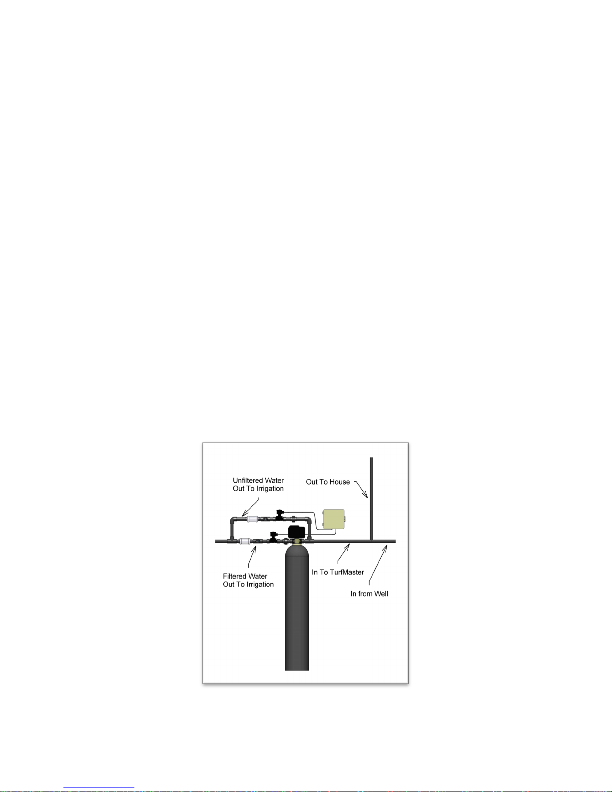
TurfMaster piping should be located on the exclusive service line to the irrigation system
(See Illustration 1). IMPORTANT: there may not be any filters installed upstream of the
TurfMaster system, or insufficient water pressure may affect operational performance.
This system and installation must comply with federal, state, and local laws and regulations.
Illustration 1
3
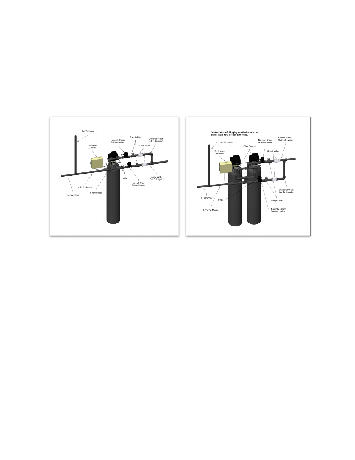
2. Fabricate system manifold: The following components have been provided for the system
manifold fabrication: bypass valve(s) with 1-1/4” socket adapters, solenoid valves with
1-1/4” socket adapters, 1-1/4” tees with sample ports, and 1-1/4” check valves. Following
Illustration 2a piping diagram for single systems, or Illustration 2b for duplex systems, construct system manifold using 1 ¼” Schedule 40 PVC pipe.
Note: IT IS CRITICAL TO NOT REDUCE ANY MANIFOLD PIPING BELOW 1 ¼”.
ANY MANIFOLD PIPE SIZE REDUCTION WILL AFFECT SYSTEM PERFORMANCE.
3. Connect drain line(s) to unit(s). Remove barbed drain line fitting(s) from parts bag. Apply
Teflon thread seal tape to threads and turn into the female threaded opening on the back side
of control valve(s) and run to a nearby drain (individual drain lines must be run for duplex
units, and these lines must not be tied together). Be sure not to submerse drain line ends into
drain, as a 1 ½” minimum air gap must be maintained to prevent potential backflow hazard.
Firmly secure at drain, while maintaining a minimum 1 ½” air gap.
4. Connect control valve(s) to electrical power source. Connect power cord(s) to a separate
120V, 15 amp ground fault interrupt (GFI) outlet.
Illustration 2a—Piping diagram for single systems Illustration 2b—Piping diagram for duplex systems
 Loading...