

Water Control Brassmaster, Brassmaster Plus, brassmaster plus+ multimax Installation & Operation Manual
Page 1

Combination Water Softener / Tannin Filter
Installation / Operation Manual
Page 2

Installation Procedure
1. Identify installation location for water softener. Piping should be such that all household
water, with the exception of outside hydrants, flows through softener. This system and installation must comply with state and local laws and regulations.
2. Connect water piping. This unit has been supplied with a manually operated bypass device
which enables the softener to be isolated from the water service lines for maintenance and
service, and also maintain the continuity of the water supply when the softener is discon-
nected. Important: Make all sweat-solder connections within 6 inches of softener before
applying threaded fittings to supplied bypass valve. Overheating may cause damage to
valve. Turn supplied bypass valve to “Bypass” position and make connections to household
water lines. Leave unit in “Bypass” position until startup procedure.
3. Connect drain line. Remove barbed drain line fitting from parts bag. Apply thread seal
tape to threads and turn into the female threaded opening on the back side of the control
valve. Connect 5/8” drain line (supplied in parts bag) to barbed end of drain line fitting and
run to a nearby drain. Be sure not to submerse drain line end into drain, as an 1 1/2” minimum air gap must be maintained to prevent potential backflow hazard. Firmly secure at
drain, while maintaining a minimum 1 1/2” air gap (See detailed drawing on back side of
piping diagram).
4. Connect brine line. Connect 3/8” brine line (supplied in parts bag) to fitting on brine tank
and on the control valve. Tighten both fittings with an adjustable wrench.
5. Install brine tank overflow line. Install overflow fitting (supplied in parts bag) into hole in
side of brine tank. An owner-supplied overflow line should then be attached and run to a
nearby drain. Failure to run overflow line could cause flooding and water damage should
the brine tank overflow.
6. Connect to electrical power source. Connect power cord to a separate 120v, 15 amp,
ground fault interrupt (GFI) outlet.
Proceed to start-up procedure.
Note: This system is not intended to be used for treating water that is microbiologically
unsafe or of unknown quality without disinfection before or after the system.
Page 3
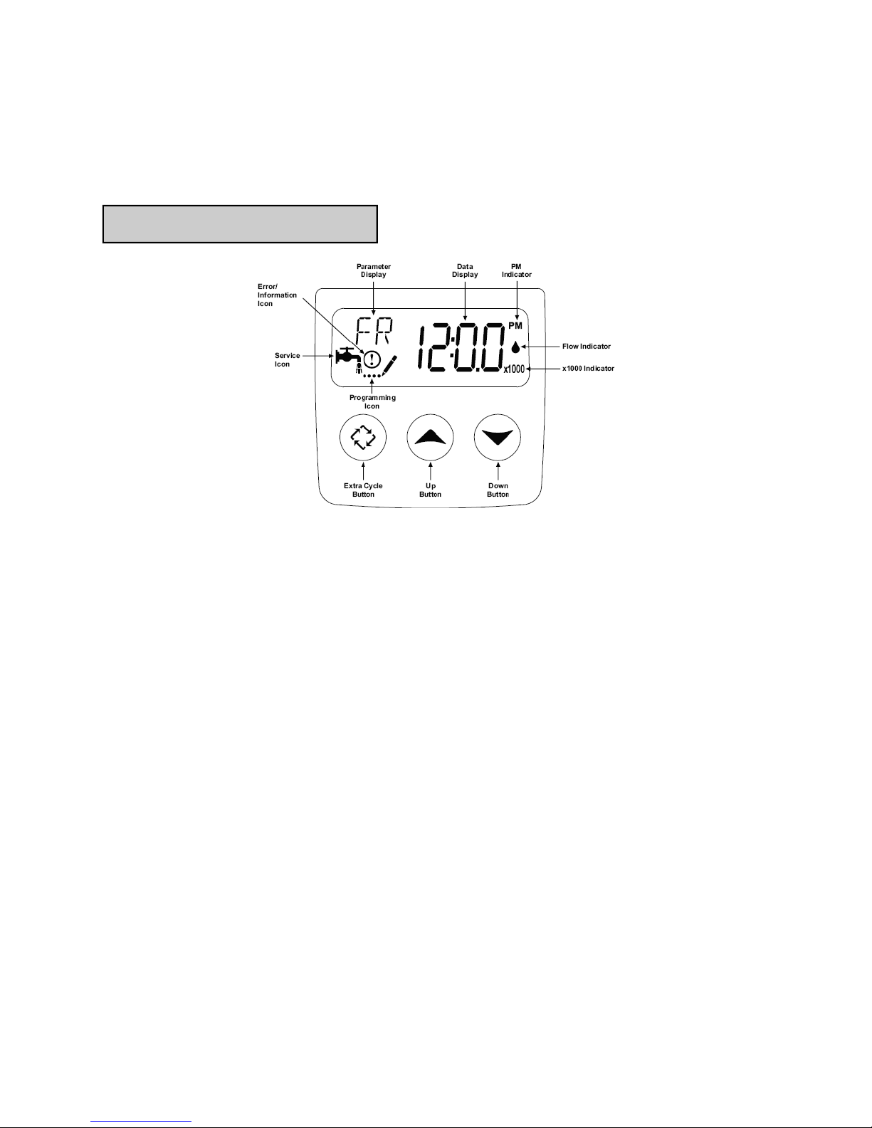
Start-Up Procedure
Placing unit into service
Fill the mineral tank with water: Press and hold the extra cycle button for 5 seconds. Dis-
play will indicate step 1, which is the backwash cycle (as shown above). Once the display
indicates step 1, slowly open bypass valve and let water run to the drain for approximately 5
minutes. This will bleed any air from the system and flush it to the drain. After approximately 5 minutes, manually index the valve through the remaining cycles as follows:
Push the extra cycle button once to advance the valve to regen step 2
Push the extra cycle button once to advance the valve to regen step 3
Push the extra cycle button once to advance the valve to regen step 4
At regen step 4, allow the control to automatically complete step 4 (brine refill) and return to
service. This will place the correct amount of water in the brine tank for start-up.
The unit is now pressurized with water and ready for service.
Proceed to setting current time of day.
Page 4
Start-Up Procedure
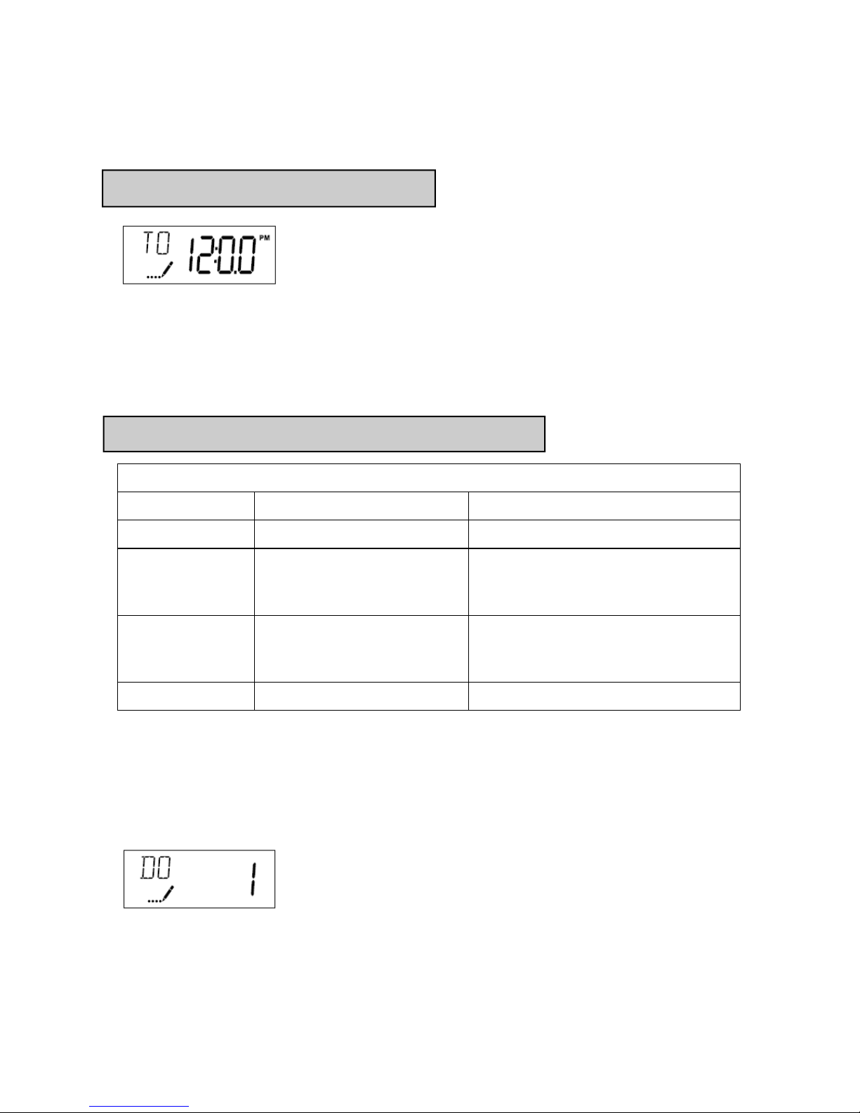
Setting current time of day
Setting Current Time / Day
1. Press either the Up or Down buttons to adjust current time of day by one digit. Push and
hold either up or down set button to adjust current time of day display by several digits.
User programming
User Programming Mode Options
Abbreviation Parameter Description
DO Day Override The timer’s day override setting
RT Regeneration Time The time of day that the system will
regenerate (meter delayed, timeclock,
and day-of-week systems)
H Feed Water Hardness The hardness of the inlet water—
used to calculate system capacity for
metered systems
RC Reserve Capacity The fixed reserve capacity
User Programming Mode Steps (Refer to chart above for user mode indications)
1. Press the Up and Down buttons for five seconds while valve is in service. Display will enter
programming mode. (Note: Timer will discard any changes and exit programming mode if
any button is not pressed for sixty seconds.
2. Set Day Override: This setting specifies the maximum number of days between regenera-
tion cycles. System will regenerate regardless of usage if the days since last regeneration
cycle equals the day override setting. This ensures regular regeneration periods. In areas of
heavy iron water conditions, this setting should not exceed 5 days.
Page 5
Start-Up Procedure
User programming (cont’d)
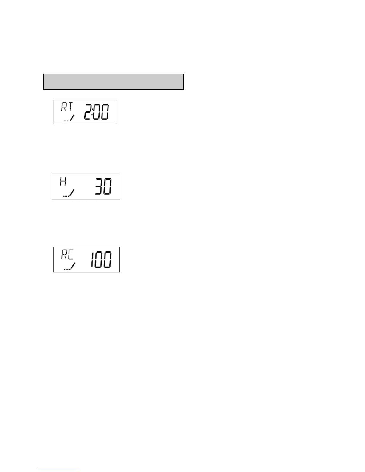
3. Adjust Regeneration Time: Press the Extra Cycle button to advance to next option. This
setting determines the time of day that the unit will enter the regeneration cycle. The most
common / default setting is 2:00 AM.
4. Set Water Hardness: Press the Extra Cycle button to advance to next option. Set the hard-
ness of the incoming water. For each PPM of iron, add 4 GPG to this setting. This will determine the amount of water usage allowed between regeneration cycles.
5. Set Fixed Reserve Capacity : Press the Extra Cycle button to advance to next option. Set
the Fixed reserve capacity for the household. This is the amount of water needed in reserve to
reach the delayed regeneration time. Standard setting is 50 gallons for each person in the
household.
Control programming is now complete. Press the extra cycle button and the control will
exit from the programming mode and resume normal operation.
Sanitization of Unit
After complete installation of unit, dilute 1/2 cup of unscented laundry bleach in 3 gallons of
water, and add to brine tank. Initiate a manual regeneration by depressing the extra cycle button. Allow the unit to complete its cycle and advance to the “Service” position. The unit is now
sanitized and ready for operation.
Page 6
Maintenance / Warranty Information
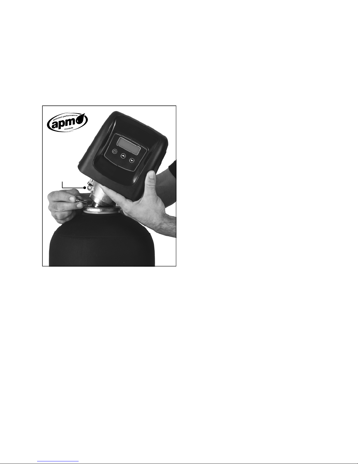
All BrassMaster and BrassMaster Plus water softeners feature the Assured Performance Modular (APM) design. If you experience a failure of any valve component, the
Nearlyallserviceable
partsliewithinthe
removable/
replaceableAPM
module.This
eliminatescostly
andmeconsuming
fieldrepairs.
brass module can be easily removed and
replaced with a factory remanufactured replacement module.
To remove module, index the bypass valve
to its “Bypass” position. Follow steps in
“Placing unit into service” to step valve
through all 4 cycles, but do not open bypass
valve. When this procedure is performed
with the bypass closed, it will relieve any
water pressure on the unit.
Remove the stainless-steel retainer pins at
the base of the module, loosen the clips at
the bypass valve, and disconnect the drain
line and brine line. The module will now
completely separate from the tank.
Please contact your dealer or Water Control
Corporation for module support.
7150143
Phone:1‐866‐405‐1268●Fax:763‐427‐5665
Forfactorymodulesupportcontact:
WaterControlCorporation
rd
AveNW●Ramsey,MN55303
www.watercontrolinc.com
Page 7

Official Warranty
Water Control Corporation
BrassMaster Plus Series Wa ter Softeners
Limited Warranty
Water Control Corporation warrants the control valve to be free of manufacturers defects for a period of 5 (five) years
from the date of installation, and the fiberglass reinforced mineral tank, and plastic brine tank, to be free from leaking due
to manufacturers defects for a period of 5 (five) years. We will, at our discretion, repair or replace defective products. This
warranty does not include any costs associated with removal of defective products, or installation of replacement products.
All replacement parts will be provided FOB Ramsey, MN. This warranty is transferable.
DISCLAIMER OF IMPLIED WARRANTIES
Water Control Corporation makes no warranties except those expressly stated in this document. To the extent permitted by
the laws of the applicable state, ALL WARRANTIES CONTAINED IN THIS DOCUMENT ARE EXPRESSLY IN
LIEU OF, AND WATER CONTROL CORPORATION EXPRESSLY DISCLAIMS, ANY AND ALL OTHER
WARRANTIES, EXPRESS OR IMPLIED, INCLUDING THE WARRANTIES OF MERCHANTABILITY AND
FITNESS FOR A PARTICULAR PURPOSE.
WHAT IS NOT COVERED BY THESE WARRANTIES
1. Conditions and damages resulting from any of the following:
- Wear caused by unfavorable water conditions
- Improper installation, delivery, or maintenance
- Any repair, modification, alteration, or adjustment not
authorized by the manufacturer or an authorized servicer
- Misuse, abuse, accidents, or unreasonable use
- Improper setting of any control
- Incorrect electric current, voltage, or supply
2. Warranties are void if the original serial numbers have been removed, altered, or cannot be readily determined.
3. The cost of service or service call to:
- Correct installation errors
- Instruct the user on proper use of the product
- Transport the product to the servicer
4. Any costs associated with removal of defective products, or installation of replacement products.
5. Consequential, special, or incidental damages sustained by any person as a result of the breach of these
warranties. Some states do not allow the exclusion or limitation of consequential or incidental damages, so the
above exclusion may not apply to you.
Page 8

WaterControlCorporation
7150143
Phone:1‐866‐405‐1268●Fax:763‐427‐5665
rd
AveNW●Ramsey,MN55303
www.watercontrolinc.com
 Loading...