

Water Connection Tank Saver Kit Easy Installation Instructions
TM
Manufactured and Distributed by:
EASY
INSTALLATION
INSTRUCTIONS
THANK YOU FOR YOUR PURCHASE
OF THE TANK SAVER KITTM.
This kit will greatly increase your water heater's life, save
energy, and reduce waste (we toss out about 7 million
heaters yearly in the U.S.). Water heater manufacturers often
explain in their maintenance manuals that periodic
replacement of the anode rod and draining sediment from the
water heater are the two most important factors in extending
tank life. The Tank Saver Kit" was designed to address these
two concerns.
It can be installed by the plumber or the handy homeowner in
either new or existing water heaters. Before you begin work,
read the instructions all the way through to insure that you
have all tools and parts needed. Should anything described
be beyond your skills, get qualified help to make sure the job
goes smoothly and safety.
You should also stop to inspect your heater at this time to be
certain it is not already beyond repair. Check all heater fittings
for signs of leakage. Check in a gas heater's combustion
chamber for heavy rusting or water marking. If you find much
damage, save this kit for installation in your replacement
heater.
TOOLS REQUIRED:
• Pipe Wrench (approximately 14")
• Large and Small Flat Head Screwdrivers
• Cheater Bar
(18" metal pipe to slip over the pipe wrench for additional leverage)
• Channel Locks
• Needle Nose Pliers
• Hack Saw
• Either a Drill with 7/8" hole saw or a Round File
A Division of Gull Industries
859 Savaker Ave., San Jose CA, 95126
Your complete tool and parts supplier for water heater maintenance.
Call 1-800-748-6286 for our free parts catalog or other information.
© Mike Kennedy 2013
& HELPFUL
INSTALLATION
TIPS
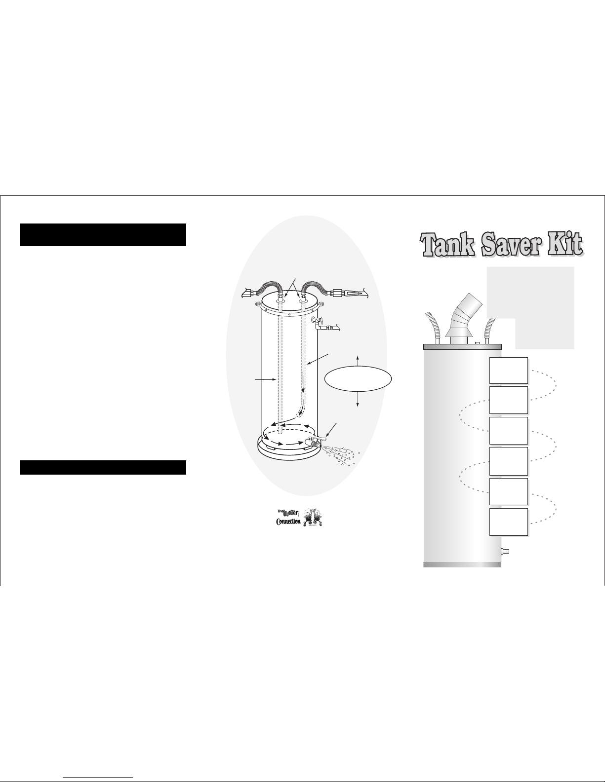
DIELECTRIC CONNECTIONS
CURVED DIP TUBE
TURBO FLUSH
TM
SEDIMENT REMOVAL
SYSTEM
ANODE ROD
FOR
SUPERIOR
CORROSION
PROTECTION
FULL-PORT
BALL DRAIN VALVE
THE IDEAL
WATER HEATER
TANK SAVER
INSTALLATION
INSTRUCTIONS
1
2
3
4
5
6
7
8
9
10
11
12
13
14
15
Electric Heaters: turn off electricity to heater.
Gas heaters: turn gas down to pilot position.
Close valve on heater's cold water supply Line. Turn on hot water at sink
or tub to release the pressure from water heater. If this water does not
quickly dwindle and stop, the cold supply is leaking past the valve. In this
case, turn off the main water supply to the building and, again, release
pressure by opening a hot tap. When water stops, close tap.
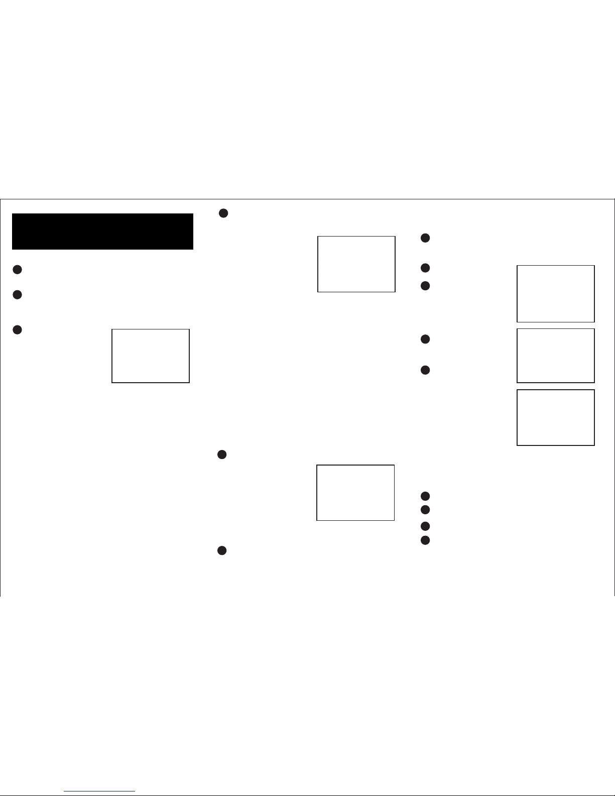
REMOVE THE DRAIN
Have a bucket, bowl or can ready
to fit under the drain valve when
removing it to catch any water
that may spill. The drain valve can
be removed with the water heater
full of water as long as all faucets
are closed and water heater is
connected to piping. Water cannot
drain from the tank unless air can
get in. (Be sure to tell others in the house not to use any faucets while
you are working on the tank).
If you have a plastic cone-shaped valve:
Unscrew the valve counter-clockwise 5-6 turns. Next, pull on valve while
turning clockwise to disengage the inner threads. Once the outer threads
of the nipple are exposed, wrap with Teflon tape. The tape must be
wrapped on these threads (clockwise) in the same direction a fitting
would screw on. Now remove the plastic drain valve and screw new
brass ball valve onto the taped nipple. Teflon tape the hose adaptor and
screw it into the brass valve. Use channel locks to tighten hose adaptor,
which will automatically tighten valve on nipple.
If you have a plastic or brass drain screwed directly into the tank:
Teflon tape both ends of a 3" plastic-lined nipple and screw into brass
ball valve by hand. Teflon and install hose adaptor in valve, also. Make
sure handle on valve swings toward hose adaptor. Use channel locks to
remove existing drain valve. Make sure jaws lock around supports
supplied on the existing valve to prevent cracking the valve.
If the plastic valve cracks stuffs rag into the opening with a screwdriver to
reduce leakage; then use a screwdriver and hammer to break out the
remaining plastic pieces. Screw in the new nipple/valve/hose adaptor
assembly. Use channel locks to tighten hose adaptor, which will tighten
other components in turn.
UNDO PIPE CONNECTIONS TO WATER HEATER
If needed, disconnect vent pipe above heater to provide working room.
Copper Pipe
Cut the copper pipe of the cold line
between the shut-off valve and the
tank, leaving approximately 2-3" of
pipe extending from the valve.
Remove the cut section from the
tank. Be sure to leave enough room
between the tank and the remaining
pipe so that the flex-connector can
be installed without kinking. Leave
a similar clearance when cutting and removing the hot line pipe from the
tank.
Attach a 3/4" compression adaptor (no soldering required) onto each
copper pipe end. (Not included in kit)
Galvanized Pipe
Unscrew union or cut pipe with hack saw at the thread. Unscrew
galvanized pipe from the cold shut-off valve. Unscrew hot line pipe at a
similar distance, perhaps at the bend where it turns to enter the wall. Use
cheater bar on pipe wrench if needed. Be cautious when dealing with old
steel plumbing). Install a brass nipple into the cold shut-off valve and a
plastic-lined steel nipple into the hot side for connection to flexconnectors.
Flexible Copper Flex Connections
If your tank is already installed with flex-connectors, make sure they are
attached to the correct type of nipple (plastic lined or brass). Also, when
disconnecting flex-connectors, check gaskets for pliability. Replace
gaskets if they have become hard. (To remove, pry out gasket with small
flat screwdriver or unscrew the nut from connector's end. Since these
washers can be difficult, you may have to replace the flex-connector.)
REMOVE DIP TUBE ON COLD WATER INLET
For ease of removal scrape out any
rust accumulated above the dip
tube using a small, flat screwdriver.
Use needle nose pliers to remove
dip tube by pulling it up and out. (If
the dip tube falls into the tank it can
be left there. It will not cause any
harm.) The dip tube is easier to
grasp if you bend one side of the
tube in with a small screwdriver and
then slip 1/2 of the pliers in beside
the screwdriver. Grip the dip tube then and rotate the pliers while pulling
up. Even the most stubborn dip tube can be removed this way.
Bore out hot and cold inlets. Some metal or glass lining protrusion may be
evident just below the tank inlet threads which may interfere with the
installation of the dip tube or anode rod. Check for this by sliding your
finger in beyond the threads. Or simply insert dip tube and anode to see if
there are any restrictions. If restrictions are evident, use a 7/8" metal-
cutting hole saw and drill out. Or, you can use a round file, but be very
careful not to damage the pipe threads. If available a 29/32 drill bit will
produce the best clearance.
Teflon the threads on the anode and dip tube. Four wraps of Teflon is
sufficient. As a directional indicator mark dip tube nipple with felt pen at
180° from dip tube opening. Tighten dip tube nipple to tank till mark is
facing you, curve is facing rear of tank.
Next, install the combination
anode rod in the hot outlet port.
Attach flex-connectors to hot and
cold line pipes and to hot and cold
port nipples for ease of access.
Use Teflon tape on all threaded
fittings. After six months, tighten
the connections once again.
These may start leaking if not retightened.
Turn water back on and check all
connections for evidence of
leakage. Bleed air from lines by
turning on taps in house.
Hook garden hose to drain valve
and open valve to flush tank.
Flush under full pressure until
water coming out of the hose is
clear. It will take from two to ten
minutes. Periodically check rinse
water by filling a bucket. When
little or no sediment settles to the
bottom the tank is as clean as
flushing can make it. Good water
pressure (50-60 PSI) and
unobstructed piping will make
flushing much more effective.
Note:
To greatly enhance the removal of
sediment from the bottom of the water heater use our exclusive TURBO FLUSHtm method.
First mark the nipple on the dip tube with a felt pen so the mark is facing you. While flushing
under pressure loosen the brass half nut on cold water flex connector attached to dip tube
nipple one full turn. Then rotate dip tube nipple counter clockwise 180° so scale is flushed in
opposite direction. When water from hose is running clean turn dip tube nipple back to original
position using the pen mark as an indicator and retighten flex connector half nut to dip tube
nipple. Flush in that position till clean.
Turn electricity back on or turn gas knob up from pilot.
Place sticker on tank to mark the date the tank was flushed, when the
new anode was installed, and when the next service is required.
If you are in an earthquake area, install an adequate restraint strap.
Test the relief valve now and every year. If it does not allow good water
flow out, or if it leaks after testing replace it. This safety feature must not
be ignored. It is what protects your water heater from exploding if
equipment malfunctions.
FLUSHING IS RECOMMENDED EVERY SIX MONTHS. CHECK THE
ANODE EVERY 1-2 YEARS WITH ARTIFICIALLY SOFTENED WATER
AND EVERY 3-5 YEARS IN UNSOFTENED WATER.
3
4
5
7
8
9
 Loading...