

Waterco Turbotemp 200HD, Turbotemp 400HD, Turbotemp 300HD Installation And Operation Manual
www.waterco.com
WARNING
!
Installation and
Operation Manual
FOR YOUR SAFETY - READ BEFORE OPERATING
• If you do not follow these instructions exactly, a re or explosion may result, causing
property damage, personal injury or loss of life.
• Improper installation, adjustment, alteration, service or maintenance can cause
property damage, personal injury or death. Installation and service must be performed
by a qualied installer, service agency or the gas supplier.
• Do not place articles or against this appliance.
• Do not use or store ammable materials near this appliance.
• Do not spray aerosols in the vicinity of this appliance while it is in operation.
WHAT TO DO IF YOU SMELL GAS
• Do not try to light any appliance.
• Do not touch any electrical switch; do not use any phone in your building.
• Immediately call your gas supplier from a neighbor’s phone.
Follow the gas supplier’s instructions.
• If you cannot reach your gas supplier, call the re department.
240 VAC NATURAL GAS/LP GAS
MODELS Natural Propane
200HD (200 MJ/h) 270201 270202
300HD (300 MJ/h) 270301 270302
400HD (400 MJ/h) 270401 270402
FOR YOUR SAFETY – This product must be installed and serviced
by authorized personnel, qualified in pool/spa heater installation.
Improper installation and/or operation can create carbon monoxide
gas and flue gases which can cause serious injury, property damage,
or death. As an additional measure of safety, Pentair Water Pool and
Spa, Inc. strongly recommends installation of suitable Carbon
Monoxide detectors in the vicinity of this heater. Improper installation
and/or operation will void the warranty.

Section 1. Heater Identification ............... 2
Information (HIN)
Heater Data Rating Plate ......................... 2
Section 2. Introduction ............................ 3
Important Notices ...................................... 3
Warranty Information ................................. 4
Code Requirements ................................... 4
Consumer Information and ........................ 5
Safety Information
General Specications ............................... 8
Section 3. Installation .............................. 9
Heater Description ...................................... 9
Sequence of Operation .............................. 10
Putting the Heater into Service .................. 10
Specications ............................................ 11
Plumbing Connections ............................... 12
Valves ......................................................... 12
Manual By-Pass ......................................... 12
Water Connections ..................................... 13
Below Pool Installation ............................... 13
Gas Connections ........................................ 14
Gas Pipe Sizing .......................................... 15
Sediment Trap/Drip Leg .............................. 15
Testing Gas Leaks and Gas Pressure ......... 15
Gas Pressure Requirements ....................... 16
Outdoor Installation / ................................. 16
Heater Clearances
Indoor Venting—General Requirements ..... 18
Heater Clearances / Outside Vent Removal
Combustion Air Supply / Corrosive ............ 20
Vapors and Possible Causes
Vent Installation (Indoor Installation or ........ 21
Outdoor Shelter) - Vertical Venting
Horizontal or Vertical Venting - Using ......... 24
Single-Wall Stainless Gas Vent
Connecting Single-Wall Stainless ............... 25
Steel Vent to the Heater
Horizontal or Vertical Venting Flexible ....... 28
Duct (Flex-Vent)
Corrosive Vapors and Possible Causes ...... 28
Control Panel Indexing ............................... 29
Final Installation Check .............................. 29
Electrical Connections ............................... 29
Fireman’s Switch Connection/ ................... 30
Remote Control Connections
Turbotemp Wiring Diagram / ...................... 32
Electrical Schematic Ladder Diagram
Section 4. Operation ................................ 34
Basic System Operation / HSI ................... 34
(Hot-Surface Ignition) Lighting/Operation
Operating Instructions ............................... 35
To Turn Off Gas to Appliance ..................... 36
Safety Controls (Air Flow Switch / .............. 37
Water Pressure Switch / Hight Limits /
Operation of Ignitiion Module)
Operating the Control Panel / .................... 38
Temperature Setting / Maximum
Temperature Set Point
Section 5. Troubleshooting ...................... 40
Initial Troubleshooting and ......................... 40
Troubleshooting Chart
Heater Will Not Fire Troubleshooting .......... 41
(A, B, C, D)
LED Diagnostics ......................................... 45
(AGS, AFS, HLS, PS Thermistor)
Burner / Heat Exchanger Troubleshooting .. 47
Section 6. Maintenance ............................ 48
Care and Maintenance ............................... 48
Pressure Relief Valve .................................. 49
After Start-Up ............................................. 49
Spring, Fall (Autumn) and ........................... 49
Winter Operation
Maintaining Pool Temperature / .................. 51
Energy Saving Tips
Chemical Balance ....................................... 51
Replacement Parts ..................................... 54
I pg 02
Section 1. Heater Identification Information
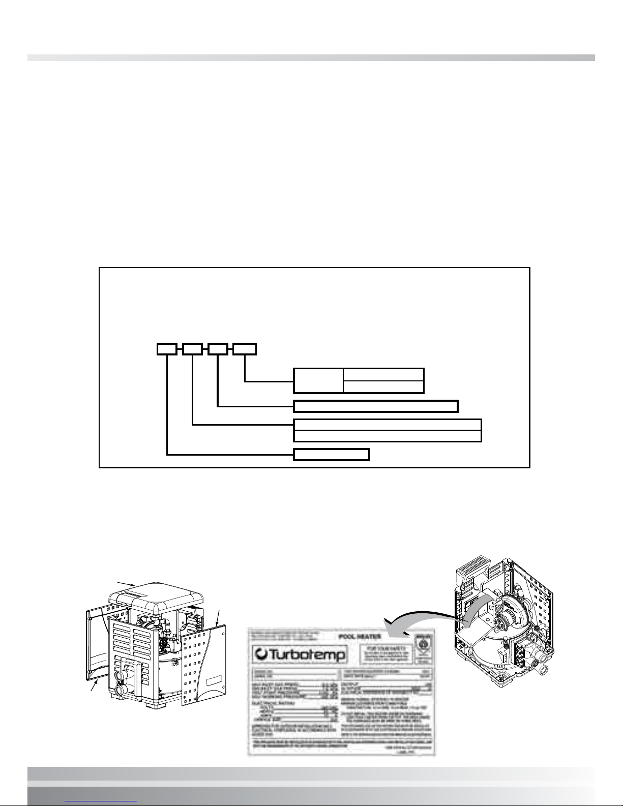
HEATER IDENTIFICATION INFORMATION (HIN)
To identify the heater, see the data rating plate on the inner front panel of the heater. There
are two designators for each heater, one is the Model Number and the other is the Heater
Identication Number (HIN).
Heater Identification Number (HIN)
The following example simplies the identication system:
1. MT : Turbotemp
2. Model Size : (200, 300 or 400) : Input rating (Mega Joule [MJ]/hr)
3. Construction : (HD = Heavy Duty Model)
4. Fuel Type : (LP = Propane gas or N = Natural gas)
MT 300HD
N
H. I. N.
HEATER IDENTIFICATION NUMBER
ID DESIGNATOR FOR WATERCO WATER POOL & SPA TURBOTEMP HEATERS
Example:
1 2 3 4
MT = TURBOTEMP
HD = HEAVY DUTY MODEL
FUEL TYPE =
N = NATURAL GAS
LP = PROPANE GAS
MODEL SIZE = MJ INPUT = Mega Joule [MJ] / HR
200 (200[MJ]/ HR), 300 (300[MJ]/ HR) or 400 (400[MJ] /HR)
HEATER DATA RATING PLATE
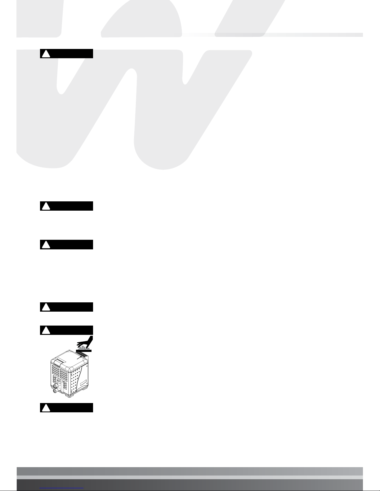
The heater data rating plate is located on the inner front panel of the heater. To access the data
rating plate, unbolt and remove the side door access panel as shown below.
Heater Data Rating Plate Location
Door
Access
Panel
Top Panel
Door
Access Panel

INTRODUCTION
Turbotemp (Australia) Pool and Spa Heater
Congratulations on your purchase of a Turbotemp high performance heating system. Proper
installation and service of your new heating system and correct chemical maintenance of
the water will ensure years of enjoyment. The Turbotemp is a compact, lightweight, efcient,
induced-draft, gas red high performance pool and spa heater that can be directly connected
to schedule 40 PVC pipe. The Turbotemp also comes equipped with the Pentair Water Pool and
Spa® multifunction temperature controller which shows, at a glance, the proper functioning of
the heater. All Turbotemp heaters are designed with a direct ignition device, HSI (hot-surface
ignition), which eliminates the need for a standing pilot. The Turbotemp requires an external
power source (240 VAC 50 Hz) to operate.
SPECIAL INSTRUCTIONS TO OWNER: Retain this manual for future reference. This instruction
manual provides operating instructions, installation and service information for the Turbotemp
high performance heater. The information in this manual applies to all Turbotemp models. READ
AND REVIEW THIS MANUAL COMPLETELY, it is very important that the owner/installer read
and understand the section covering installation instructions, and recognize the local and state
codes before installing the Turbotemp. Its use will reduce service calls and chance of injury
and will lengthen product life. History and experience has shown that most heater damage is
caused by improper installation practices.
IMPORTANT NOTICES
THIS PRODUCT MUST BE INSTALLED AND SERVICED BY A PROFESSIONAL SERVICE
TECHNICIAN, QUALIFIED IN POOL HEATER INSTALLATION.
For the installer and operator of the Turbotemp pool and spa heater: The manufacturer’s
warranty may be void if, for any reason, the heater is improperly installed and/or operated. Be
sure to follow the instructions set forth in this manual. If you need more information or if you
have any questions regarding to this pool heater, please contact.
Waterco Limited - Offices Australia
NSW - Sydney (HEAD OFFICE)
Tel : +61 2 9898 8686
VIC/ TAS - Melbourne
Tel : +61 3 9764 1211
WA - Perth
Tel : +61 8 9273 1900
QLD - Brisbane
Tel : +61 7 3299 9900
SA/ NT - Adelaide
Tel : +61 8 8244 6000
Waterco (NZ) Limited
Auckland, New Zealand
Tel : +64 9 525 7570
I pg 04
Section 2. Introduction
WARRANTY INFORMATION
The Turbotemp pool heater is sold with a limited factory warranty. Specific details are described
in the Waterco Warranty Terms and Conditions booklet included with the product.
Waterco pool and spa’s high standards of excellence include a policy of continuous product
improvement resulting in your state-of-the-art heater. We reserve the right to make improvements
which change the specications of the heater without incurring an obligation to update the
current heater equipment.
These heaters are designed for the heating of chlorine, bromine or salt system swimming
pools and spas or in non-stationary installations, and should never be employed for use
as space heating boilers or general purpose water heaters. The manufacturer’s warranty
may be void if, for any reason, the heater is improperly installed and/or operated. Be sure
to follow the instructions set forth in this manual.
OPERATING THIS HEATER CONTINUOUSLY AT WATER TEMPERATURE BELOW 20°C.
WILL CAUSE HARMFUL CONDENSATION AND WILL DAMAGE THE HEATER AND VOID
THE WARRANTY. Do not use the heater to protect pools or spas from freezing if the
final maintenance temperature desired is below 20°C., as this will cause condensation
related problems.
!
CAUTION
CARBON MONOXIDE GAS IS DEADLY – Exhaust from this pool heater contains toxic
levels of carbon monoxide, a dangerous, poisonous gas you cannot see or smell.
!
DANGER
CODE REQUIREMENTS
Installation must be in accordance with the following:
• Manufacturer’s Installation Instructions
• AS/NZS 5601.1 for Gas Installations
• Local Gas Fitting Regulations,
• Municipal Building Codes,
• S.A.A. Wiring Code,
• Local Electrical Regulations
• Any other statutory regulations
CONSUMER INFORMATION AND SAFETY
The U.S. Consumer Product Safety Commission warns that carbon monoxide is an
“invisible killer”. Carbon monoxide is a colorless and odorless gas.
!
WARNING
1. Carbon monoxide is produced by burning fuel, including natural gas and propane.
2. Proper installation, operation and maintenance of fuel-burning appliances in the home is the
most important factor in reducing carbon monoxide poisoning.
3. Be sure that fuel burning appliances such as heaters are installed by professionals according
to manufacturer’s instructions and codes.
4. Always follow the manufacturer’s directions for safe operation.
5. Have the heating system (including vents) inspected and serviced annually by a trained
service technician.
6. Examine vents regularly for improper connections, visible cracks, rust or stains.
7. Install battery-operated carbon monoxide alarms. The alarms should be certied to the
requirements of the most recent UL, IAS, CSA and IAPMO standard for carbon monoxide
alarms. Test carbon monoxide alarms regularly and replace dead batteries.
The U.S. Consumer Product Safety Commission warns that elevated water
temperature can be hazardous. See below for water temperature guidelines before
setting temperature.
!
WARNING
1. Spa or hot tub water temperatures should never exceed 40° C. A temperature of 37° C.
is considered safe for a healthy adult. Special caution is suggested for young children.
Prolonged immersion in hot water can induce hyperthermia.
2. Drinking of alcoholic beverages before or during spa or hot tub use can cause drowsiness
which could lead to unconsciousness and subsequently result in drowning.
3. Pregnant women beware! Soaking in water above 37° C. can cause fetal damage during the
rst three months of pregnancy (resulting in the birth of a brain-damaged or deformed child).
Pregnant women should stick to the 37° C. maximum rule.
4. Before entering the spa or hot tub, the user should check the water temperature with an
accurate thermometer. Spa or hot tub thermostats may err in regulating water temperatures
by as much as -15° C.
5. Persons with a medical history of heart disease, circulatory problems, diabetes or blood
pressure problems should obtain their physician’s advice before using spas or hot tubs.
6. Persons taking medication which induce drowsiness, such as tranquilizers, antihistamines
or anticoagulants should not use spas or hot tubs.
Should overheating occur or the gas supply fail to shut off, turn off the manual gas
control valve to the heater. Do not use this heater if any part has been under water.
Immediately call a qualified service technician to inspect the heater and to replace any
part of control system and gas control which has been under water.
!
WARNING

I pg 06
Section 2. Introduction
!
DANGER
SAFETY INFORMATION
The Turbotemp pool heaters are designed and manufactured to provide many years of safe and
reliable service when installed, operated and maintained according to the information in this
manual. Throughout the manual, safety warnings and cautions are identied by the
“ “symbol. Be sure to read and comply with all of the warnings and cautions.
!
CARBON MONOXIDE GAS IS DEADLY
• • READ OWNERS MANUAL COMPLETELY BEFORE OPERATING. • •
THIS PRODUCT MUST BE INSTALLED AND SERVICED BY A
PROFESSIONAL SERVICE TECHNICIAN, QUALIFIED IN POOL HEATER
INSTALLATION. Some jurisdictions require that installers be licensed. Check
with your local building authority about contractor licensing requirements.
Improper installation and/or operation could create carbon monoxide
gas and ue gases which could cause serious injury or death. Improper
installation and/or operation will void the warranty.
Exhaust from this pool heater contains carbon monoxide, a dangerous,
poisonous gas you cannot see or smell. Symptoms of carbon monoxide
exposure or poisoning include dizziness, headache, nausea, weakness,
sleepiness, muscular twitching, vomiting and inability to think clearly. IF YOU
EXPERIENCE ANY OF THE ABOVE SYMPTOMS, IMMEDIATELY TURN
OFF THE POOL HEATER, LEAVE THE VICINITY OF THE POOL OR SPA
AND GET INTO FRESH AIR IMMEDIATELY. THE POOL HEATER MUST BE
THOROUGHLY TESTED BY A GAS PROFESSIONAL BEFORE RESUMING
OPERATION.
EXCESSIVE CARBON MONOXIDE EXPOSURE CAN CAUSE BRAIN
DAMAGE OR DEATH.
Install this pool heater far from open windows, doors, vents and other
openings, see page 16 for minimum distances.
Waterco strongly recommends that all vents, pipes and exhaust systems
be initially and periodically tested for proper operation. This testing can
be accomplished by using a hand-held carbon monoxide meter and/or by
consulting with a gas professional. Pool heaters must be used in conjunction
with carbon monoxide detectors installed near the pool heater. The carbon
monoxide detectors must be periodically inspected for proper operation so
as to insure continued safety. Broken or malfunctioning carbon monoxide
detectors must be replaced immediately.
This heater is equipped with an unconventional gas control valve that
is factory set with a manifold pressure of 11 ± 5 Pa. Improper installation,
adjustment, alteration, service or maintenance can cause property damage,
personal injury or loss of life. Installation or service must be performed by
a qualied installer, service agency or the gas supplier. If this control is
replaced, it must be replaced with an identical control.
Do not attempt to adjust the gas flow by adjusting the regulator setting.
!
WARNING
Risk of re or explosion from incorrect fuel use or faulty fuel conversion.
Do not try to run a heater set up for natural gas on propane gas or vice
versa. Only qualied service technicians should attempt to convert heater
from one fuel to the other. Do not attempt to alter the rated input or type of
gas by changing the orice. If it is necessary to convert to a different type
of gas, consult your Waterco dealer. Serious malfunction of the burner can
occur which may result in loss of life. Any additions, changes, or conversions
required in order for the appliance to satisfactorily meet the application
needs must be made by a Waterco dealer or other qualied agency using
factory specied and approved parts. The heater is available for use with
natural gas or LP (propane) gas only. It is not designed to operate with any
other fuels. Refer to the nameplate for the type of gas the heater is equipped
to use.
• Use heater only with the fuel for which it is designed.
• If a fuel conversion is necessary, refer this work to a qualied service
technician or gas supplier before putting the heater into operation.
Risk of fire or explosion from flammable vapors. Do not store gasoline,
cleaning uids, varnishes, paints, or other volatile ammable liquids near
heater.
Risk of explosion if unit is installed near propane gas storage. Propane
(LP) gas is heavier than air. Consult local codes and re protection authorities
about specic installation requirements and restrictions. Locate the heater
away from propane gas storage and lling equipment as specied by the
Standard for the Storage and Handling of Liqueed Petroleum Gases (latest
edition).
Risk of fire. Do not place articles on, near or against the heater.
Risk of burn hazard. To reduce the risk of injury, do not touch the side
heater vent cover when the heater is operating. Side heater vent covers
are HOT and can burn when touched causing personal injury. Do not allow
children to play on or around heater or associated equipment.
Risk of asphyxiation if exhaust is not correctly vented. Follow venting
instructions exactly when installing heater. Do not use a drafthood with
this heater, as the exhaust is under pressure from the burner blower and
a draft hood will allow exhaust fumes to blow into the room housing the
heater. The heater is supplied with an integral venting system for outdoor
installation.
!
WARNING
!
WARNING
!
WARNING
!
WARNING
!
WARNING
!
WARNING
Vent
Cover

I pg 08
Section 2. Introduction
!
CAUTION
Label all wires prior to disconnection when servicing controls. Wiring
errors can cause improper and dangerous operation. Wiring errors can
also destroy the control board.
• Connect heater to 240 Volt, 50 Hz., Single Phase power only.
• Verify proper operation after servicing.
• Do not allow children to play on or around heater or associated equipment.
• Never allow children to use the pool or spa without adult supervision.
• Read and follow other safety information contained in this manual prior to
operating this pool heater.
GENERAL SPECIFICATIONS
NOTICE:
• Combustion air contaminated by corrosive chemical fumes can damage the heater and will
void the warranty.
• The Combination Gas Control Valve on this heater differs from most appliance gas controls.
If it must be replaced, for safety reasons replace it only with an identical gas control.
• The access door panels must be in place to provide proper ventilation. Do not operate the
heater for more than ve (5) minutes with the access door panels removed.
• This heater is design certied by IAPMO as complying with the Standard for Gas Fired Pool
Heaters, and is intended for use in heating fresh water swimming pools or spas.
• The heater is designed for the heating of chlorine, bromine or salt system swimming pools
and spas. It should NOT be used as a space heating boiler, or general purpose water heater.
The heater requires an external 240 VAC single-phase electric power source.
• The heater should be located in an area where leakage of the heater or connections will not
result in damage to the area adjacent to the heater or to the structure. When such locations
cannot be avoided, it is recommended that a suitable drain pan, adequately drained, be
installed under the heater. The pan must not restrict air ow.
• The heater may not be installed within 3.5M (11.5 ft.) of the inside surface of a pool or spa
unless it is separated by a solid fence, wall or other permanent barrier.
INSTALLATION INSTRUCTIONS
THIS PRODUCT MUST BE INSTALLED AND SERVICED BY A PROFESSIONAL SERVICE
TECHNICIAN, QUALIFIED IN POOL HEATER INSTALLATION.
Waterco strongly recommends that all vents, pipes and exhaust systems be initially and
periodically tested for proper operation. This testing can be accomplished by using a handheld carbon monoxide meter and/or by consulting with a gas professional.
Pool heaters must be used in conjunction with carbon monoxide detectors installed near the
pool heater. The carbon monoxide detectors must be periodically inspected for proper operation
so as to insure continued safety. Broken or malfunctioning carbon monoxide detectors must be
replaced immediately.
HEATER DESCRIPTION
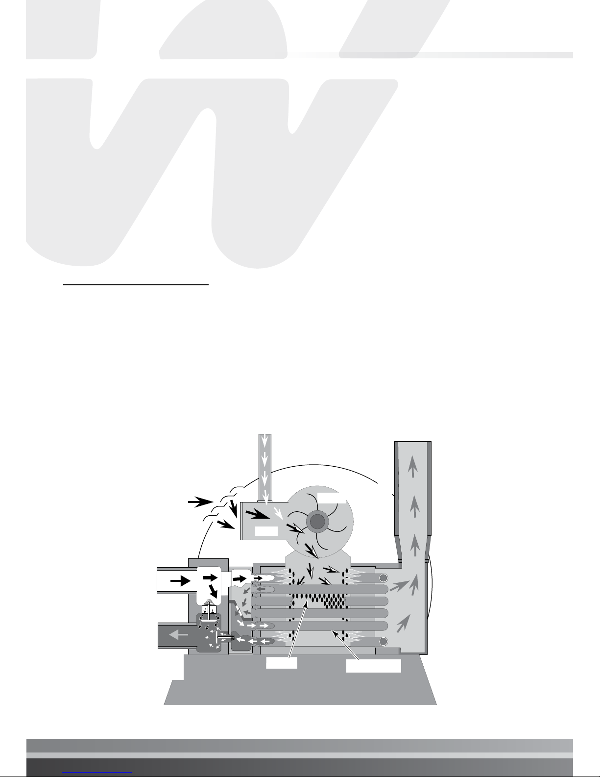
Figure 1 is a diagram of the heater showing how it operates. Precisely matched orice plates
meter the air and gas into the mixer. The blower draws the air and gas through the mixer and
forces it into the burner’s ame holder. A sealed heat exchanger surrounds the ame holder,
discharging exhaust gases out the ue.
Five (5) cm PVC water piping connects directly to the manifold/ header on the heat exchanger
using 5 cm PVC slip unions provided with the heater. The outer manifold remains cool; no heat
sinks are required. A thermal regulator and an internal bypass regulate the water ow through
the heat exchanger to maintain the correct outlet temperature. The heater operator control
panel board assembly is located on top of the heater.
Gas
Air
Mixer
Blower
Inlet
(Cold
Water)
Exhaust
Heating Coils
Outlet
(Mixed
Water)
Burner
Figure 1.

I pg 10
Section 3. Installation
SEQUENCE OF OPERATION
An electronic temperature sensing thermistor in the manifold adapter inlet controls the heater
operation. When the inlet water temperature drops below the temperature set on the operating
control, the burner controller supplies power to the combustion air blower through a series
of safety interlocks. The interlocks consist of:
• the pressure switch (PS), which senses that the pump is running,
• the high limit switch (HLS), which opens if the heat exchanger outlet temperature goes
above 53° C (127° F), and
• the air flow switch (AFS), which senses the pressure drop across the air metering orice,
• the automatic gas shut-off (AGS) switch, which opens if the heat exchanger outlet
temperature goes above 60° C (140° F).
• the stack flue sensor (SFS), which shuts down the heater if the ue gas temperature
reaches 249° C (480° F).
• the high limit switch (HLS), which opens if the heat exchanger outlet temperature
goes above 55° C (131° F), and....
• the inlet temperature control switch, which opens if the inlet temperature goes above
45° C (110° F).
The air ow switch (AFS) senses the pressure drop across the air metering orice. As soon as
there is sufcient air ow, the AFS closes, closing the circuit to the hot surface igniter (HSI),
which ignites the fuel mixture. On a call for heat, the blower and HSI are energized. In about 20
seconds, the gas valve opens and ignition occurs. The HSI then switches to a sensing mode
and monitors the ame.
The heater is equipped with a digital operating control that enables the user to pre-set the
desired pool and spa water temperatures. The control enables the user to select between pool
and spa heating, and features a digital display that indicates the water temperature.
PUTTING THE HEATER INTO SERVICE
If the heater is installed below the level of the pool, or more than 0.6 meters (2 feet) above
pool level, the pressure switch setting should be adjusted. See “WATER PRESSURE SWITCH”
in the “SAFETY CONTROLS Section” (page 32) and the “CAUTION” under “BELOW POOL
INSTALLATION Section” (page 12).
Before putting the heater into service for the rst time, follow the instructions under “BEFORE
START-UP” (page 30) in the front of this manual. Check for proper operation of the heater by
following the steps under “OPERATION INSTRUCTIONS.”
Damage to equipment caused by improper installation or repair will void the warranty.
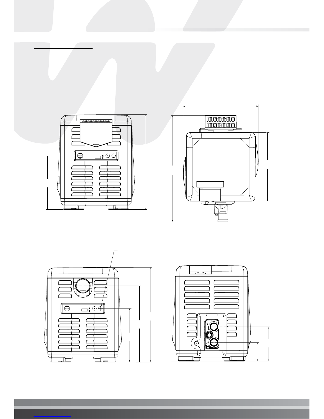
SPECIFICATIONS
These installation instructions are designed for use by qualied personnel only, trained especially
for installation of this type of heating equipment and related components. Some states require
installation and repair by licensed personnel. If this applies in your state, be sure your contractor
bears the appropriate license. See Figure 2 for Outdoor Installations.
DIMENSIONS IN CENTIMETERS & INCHES
53.3 cm
(21.0")
82.8 cm
(32.61")
58.5 cm
(23.02")
71.5 cm
(28.15")
40.6 cm
(16")
TOPFRONT
EXHAUST SIDE PLUMBING SIDE
25.7 cm
(10.13")
14.2 cm
(5.6")
ELECTRICAL
CONDUIT PORT
71.6 cm
(28.2")
57.7 cm
(22.7")
40.6 cm
(16.0")
Figure 2.
I pg 12
Section 3. Installation
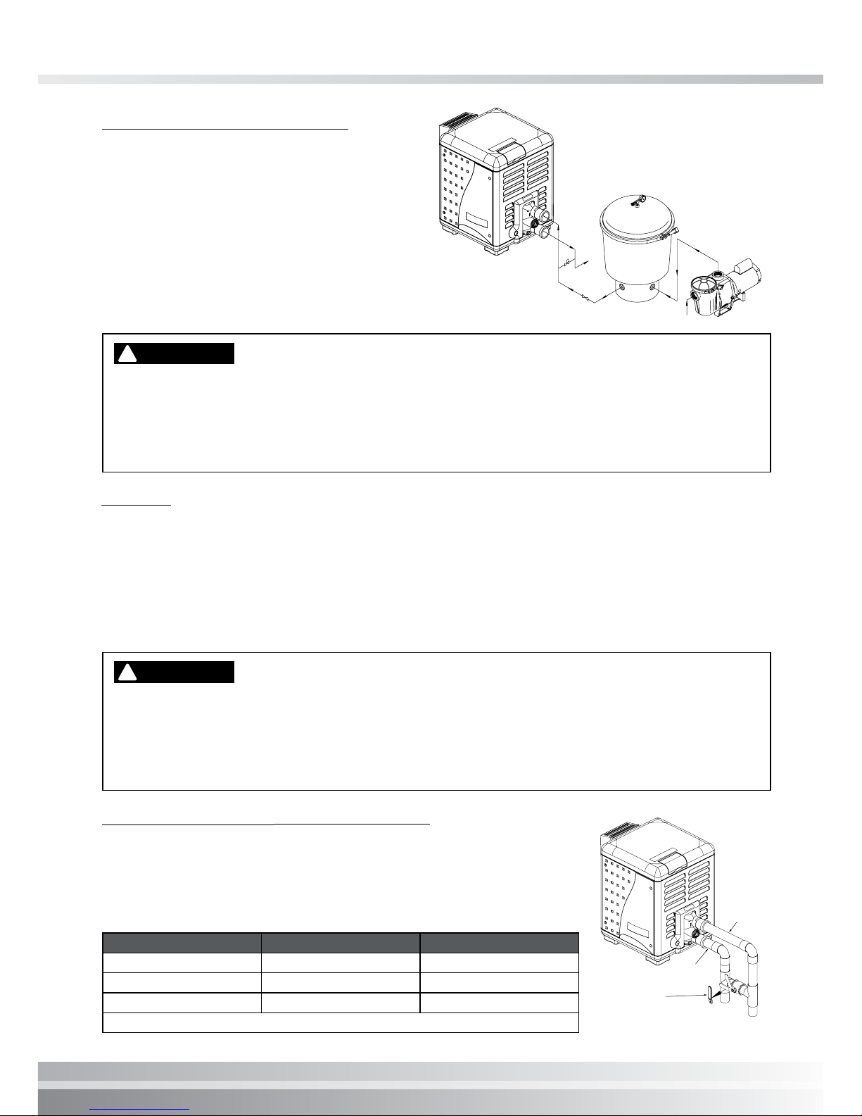
PLUMBING CONNECTIONS
The Turbotemp heater has the unique
capability of direct schedule 40
PVC plumbing connections. A set of
bulkhead ttings is included with the
Turbotemp to insure conformity with
Waterco’s recommended PVC plumbing
procedure. Other plumbing connections
can be used. See Figure 3 for plumbing
connections.
Before operating the heater on a new installation, turn on the circulation pump and
bleed all the air from the filter using the air relief valve on top of the filter. Water should
flow freely through the heater. Do not operate the heater unless water in the pool/spa
is at the proper level. If a manual by-pass is installed, temporarily close it to insure that
all air is purged from the heater.
!
CAUTION
VALVES
When any equipment is located below the surface of the pool or spa, valves should be placed
in the circulation piping system to isolate the equipment from the pool or spa. Check valves
are recommended to prevent back-siphoning. Backsiphoning is most likely to occur when
the pump stops, creating a pressure-suction differential. Do NOT sanitize the pool by putting
chlorine tablets or sticks into the skimmer(s). When the pump is off, this will cause a high
concentration of chlorine to enter the heater, which could cause corrosion damage to the heat
exchanger.
Exercise care when installing chemical feeders so as to not allow back siphoning
of chemical into the heater, filters or pump. When chemical feeders are installed in
the circulation of the piping system, make sure the feeder outlet line is down stream
of the heater, and is equipped with a positive seal noncorrosive “Check Valve”, (P/N
R172288), between the feeder and heater.
!
CAUTION
MANUAL BY-PASS ( WATER FLOW RATE)
Where the water ow rate exceeds the maximum 454 LPM, a manual
bypass should be installed and adjusted. After installing the valve,
adjust the valve to bring the ow rate within the acceptable range.
Then remove the valve handle or lock it in place to avoid tampering.
See Figure 4.
Model Min. LPM (GPM) Max. LPM (GPM) *
200 76 (20) 454 (120)
300 114 (30) 454 (120)
400 152 (40) 454 (120)
*Do not exceed the maximum recommended flow rate for the connecting piping.
See page 32 for Pressure Relief Valve Installations.
PUMP
FILTER
POOL
HEATER
MANUAL
BY-PASS
TO
POOL
GATE
VALVE
FROM POOL
Figure 3.
Cool wate
r
Warm water out
Outlet
to
pool
Inlet
to
heater
1. Set Manual
By-Pass Valve.
2. Remove Handle.
Figure 4.
Table 1.
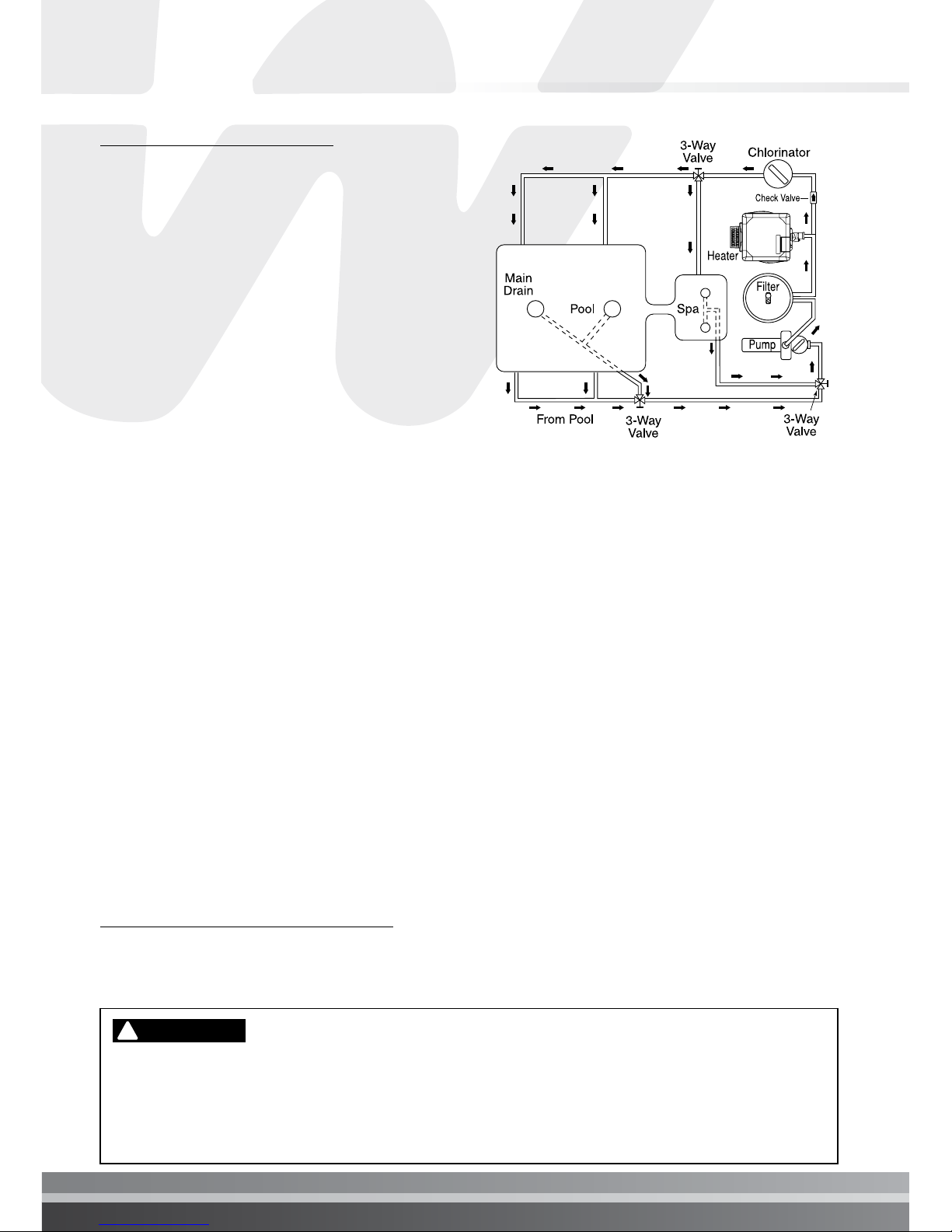
WATER CONNECTIONS
The heater requires proper water ow and
pressure for its operation. See Figure 5 for the
recommended installation. The lter pump
discharges to the lter, the lter discharges to
the heater, and the heater discharges directly to
the pool or spa.
A manual bypass valve should be installed
across the heater when the pump ow exceeds
454 LPM (120 GPM). See “WATER FLOW RATE”
on page 11 - Table 1 for setting of the manual
by-pass valve.
Make sure that the outlet plumbing from the
heater contains no shut-off valves or other ow
restrictions that could prevent ow through the
heater (except for below pool as noted below,
or winterizing valves where needed). To switch ow between the pool and spa, use a diverter
valve. Do not use any valve that can shut off the ow. Do not use a shut-off valve to isolate the
heater unless it is below the level of the pool or spa. Install the chemical feeder downstream
of the heater. Install a chemical resistant one-way check valve between the heater and the
chemical feeder to prevent back-siphoning through the heater when the pump is off.
NOTICE: If the heater is plumbed in backwards, it will cycle continuously. Make sure piping
from lter is not reversed when installing heater.
Connect the heater directly to 5 cm PVC pipe, using the integral unions provided. Heat sinks
are not required. The low thermal mass of the heater will prevent overheating of the piping
connected to the pump even if the heater shuts down unexpectedly.
Occasionally a two-speed pump will not develop enough pressure on the low speed to operate
the heater. In this case, run the pump at high speed only to operate the heater. If this does not
solve the problem, do not try to run the heater. Instead, correct the installation.
Do not operate the heater while an automatic pool cleaner is also operating. If the circulation
pump suction is plugged (for example by leaves), there may not be adequate ow to the heater.
Do not rely on the pressure switch in this case.
Local codes may require the installation of a pressure relief valve (PRV), see page 50 for
“PRESSURE RELIEF INSTRUCTIONS”.
BELOW POOL INSTALLATION
If the heater is below water level, the pressure switch must be adjusted. This adjustment must
be done by a qualied service technician.
See following CAUTION before installation.
BELOW OR ABOVE POOL INSTALLATION
The water pressure switch is set in the factory at 21 kPa (± 5 kPa). This setting is for a
heater installed at pool level. If the heater is to be installed more than 0.3 m above or
below, the water pressure switch must be adjusted by a qualified service technician.
See page 36, Figure 28.
!
CAUTION
Figure 5.
I pg 14
Section 3. Installation
FLOW SWITCH
If the heater is installed more than 1.5 m above the pool or more than 1.2 m below the
pool level, you will be beyond the limits of the pressure switch and a flow switch must
be installed. Locate and install the flow switch externally on the outlet piping from the
heater, as close as possible to the heater. Connect the flow switch wires in place of the
water pressure switch wires.
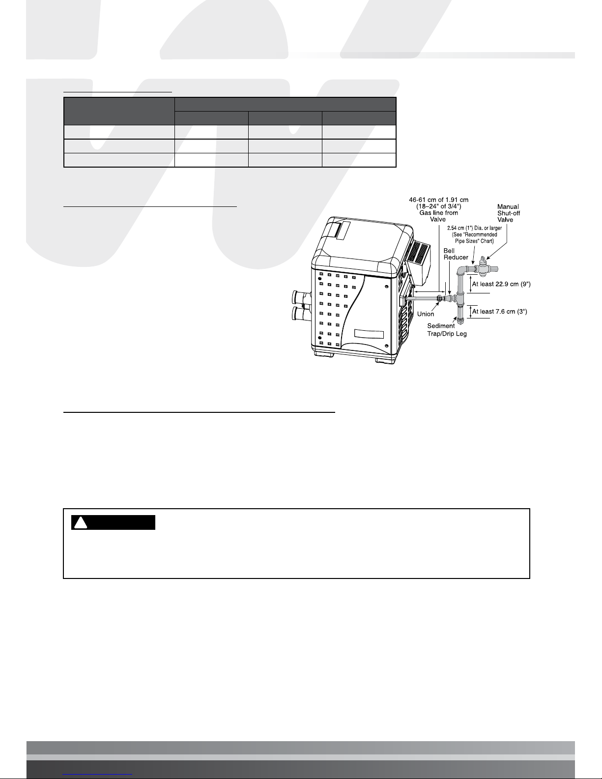
GAS CONNECTIONS
GAS LINE INSTALLATIONS
The gas supply must be installed in accordance with the Gas Installation Code, AS/NZS 5601.1,
as applicable and all applicable local codes.
Before installing the gas line, be sure to check which gas the heater has been designed to burn.
This is important because different types of gas require different gas pipe sizes. The rating plate
on the heater will indicate which gas the heater is designed to burn. Table 2 below shows the
recommended gas inlet pipe sizes required for the distance from the gas meter to the heater.
The table is for natural gas at a specic gravity of .65 and propane at a specic gravity of 1.55.
When sizing gas lines, calculate 0.9 additional meters of straight pipe for every elbow used.
When installing the gas line, avoid getting dirt, grease or other foreign material in the pipe as
this may cause damage to the gas valve, which may result in heater failure.
The gas meter should be checked to make sure that it will supply enough gas to the heater and
any other appliances that may be used on the same meter. Insufficient gas supply will cause
the heater to operate below its designed performance or not at all. The gas line from the meter
will usually be of a larger size than the gas valve supplied with the heater. Therefore a reduction
of the connecting gas pipe will be necessary. Make this reduction as close to the heater as
possible. Gas supply companies are increasingly supplying natural gas to new installations
with 2.75 kPa; this means if the gas pressure is not adjusted to the correct working pressure,
the heater will be over gassed and cause serious damage within minutes. This damage is not
covered under the heater warranty.
Install a manual shut-off valve that conforms with Type 1 or Type 2 as per AG201 and/or AS4617
standards, and a sediment trap/drip leg and union located outside the heater panels, see Figure
6. Do not use a restrictive gas cock.
The heater and any other gas appliances must be disconnected from the gas supply piping
system during any pressure testing on that system, (greater than 6.0 kPa). The heater and its
gas connection must be leak tested before placing the heater in operation. Do not use flame
to test the gas line. Use soapy water or another nonammable method.
NOTE
A manual main shut-off valve must be installed externally to the heater.
DO NOT INSTALL THE GAS LINE UNION INSIDE THE HEATER CABINET. THIS WILL
VOID YOUR WARRANTY.
!
WARNING
GAS PIPE SIZING
Heater Size
Distance from the Meter
0 to 15 m 16 to 30 m 31 to 60 m
200 25 mm 32 mm 32 mm
300 32 mm 32 mm 40 mm
400 32 mm 40 mm 50 mm
SEDIMENT TRAP/DRIP LEG
Install a sediment trap/drip leg and
union located outside the heater panels
in accordance with National code
requirements. Do not use a restrictive gas
cock. The sediment trap/drip leg shall be
either a tee tting with a capped nipple in
the bottom outlet which can be removed
for cleaning, as illustrated in Figure 6, or
an other device recognized as an effective
sediment trap/drip leg. All gas piping should
be tested after installation in accordance
with local codes.
TESTING GAS LEAKS AND GAS PRESSURE
Before operating the heater, the heater and its gas connections must be leak tested. Do NOT
use an open ame to test for leaks. Test all gas connections for leaks with soapy water.
The gas valve must be completely disconnected from the gas supply piping system during any
pressure testing of that system at test pressures in excess of 6.0 kPa (.87 psig).
TESTING THE GAS PRESSURE THROUGH THE COMBINATION GAS CONTROL VALVE
Risk of fire and explosion. Alteration, service, or maintenance of the Combination Gas
Control Valve can lead to fire or explosion, causing loss of life, personal injury, and/or
property damage. DO NOT ATTEMPT TO ADJUST THE GAS CONTROL VALVE.
!
WARNING
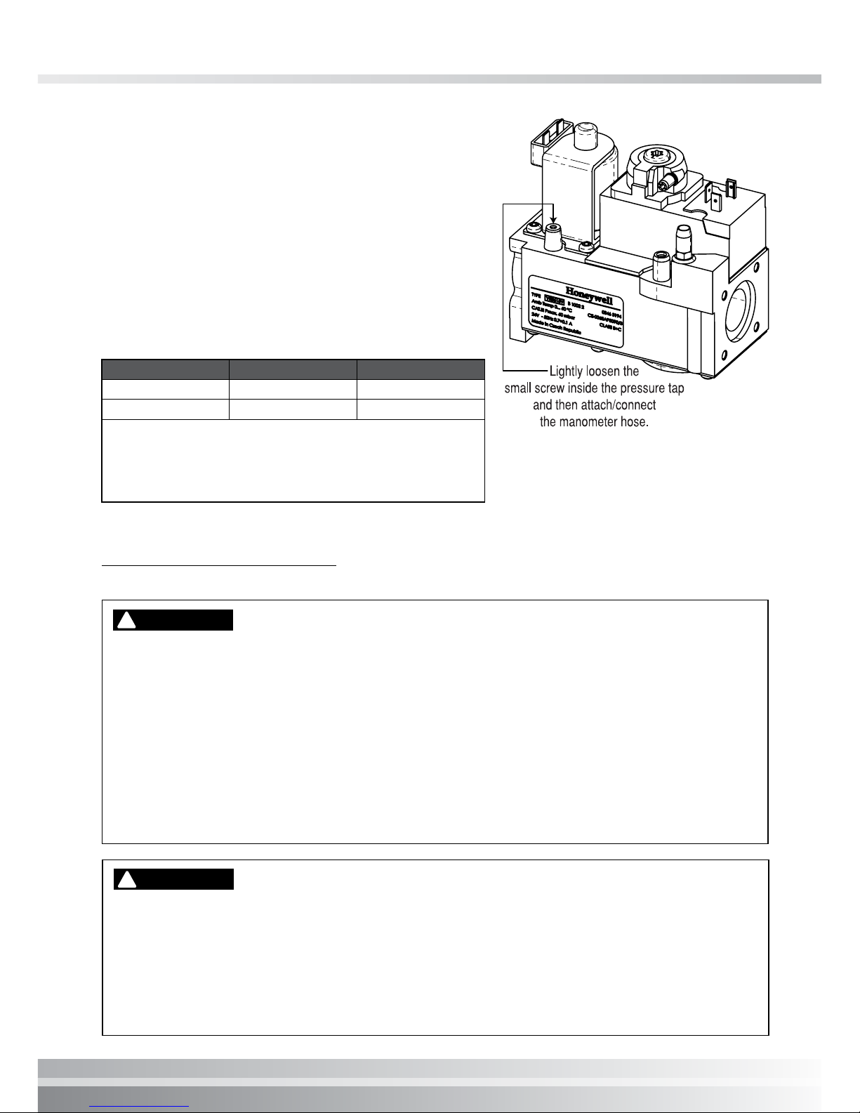
These instructions are for the use of qualified service technicians only!
1. Shut off the gas supply to the heater.
2. Loosen the small screw inside the pressure tap as shown in Figure 7.
3. Connect the manometer hose.
4. Open the gas supply to the heater.
5. Turn on the heater.
6. Take the gas pressure reading.
7. Turn off the heater.
Table 2.
Figure 6.
I pg 16
Section 3. Installation
8. Shut off the gas supply to the heater.
9. Disconnect the manometer hose.
10. Tighten the small screw inside the pressure tap.
11. Open the gas supply to the heater.
12. Verify that the seal connection in the pressure tap
is closed by testing for leaks with soapy water.
Note: If the pressure reading is out of range,
(see Table 3), regulate the incoming gas pressure.
INLET GAS PRESSURE REQUIREMENTS
Gas Pressure Minimum Maximum
Natural Gas 1.0 kPa 6.0 kPa
Propane Gas 2.5 kPa 6.0 kPa
NOTE: The minimum value approved for input adjustment.
Do not exceed the maximum supply pressure.
All readings must be taken while heater is operating. Any
adjustments or readings made while heater is off will result in
performance problems.
OUTDOOR INSTALLATION (Australia)
For heaters located outdoors, using the built-in stackless venting system.
CARBON MONOXIDE GAS IS DEADLY – Exhaust from this pool heater contains carbon
monoxide, a dangerous, poisonous gas you cannot see or smell. Symptoms of carbon
monoxide exposure or poisoning include dizziness, headache, nausea, weakness,
sleepiness, muscular twitching, vomiting and inability to think clearly. IF YOU EXPERIENCE
ANY OF THE ABOVE SYMPTOMS, IMMEDIATELY TURN OFF THE POOL HEATER, LEAVE
THE VICINITY OF THE POOL OR SPA AND GET INTO FRESH AIR IMMEDIATELY. THE
POOL HEATER MUST BE THOROUGHLY TESTED BY A GAS PROFESSIONAL BEFORE
RESUMING OPERATION.
EXCESSIVE CARBON MONOXIDE EXPOSURE CAN CAUSE BRAIN DAMAGE OR
DEATH.
!
DANGER
Risk of explosion if a unit burning propane gas is installed in a pit or other low spot.
Propane is heavier than air. Do not install the heater using propane in pits or other locations
where gas might collect. Consult your local building code ofcials to determine installation
requirements and specic installation restrictions of the heater relative to propane storage
tanks and lling equipment. Installation must meet the requirements for the Standard for the
Storage and Handling of Liquid Petroleum Gases. Consult local codes and re protection
authorities about specic installation restrictions.
!
WARNING
Figure 7.
Table 3.

OUTDOOR INSTALLATION (Australia)
Locate the heater in an open, unroofed area
and on a level surface that is protected from
drainage or run-off. Install the heater in an area
where leaves or other debris will not collect on
or around the heater.
It is recommended that a non-combustible base
be a platform under the heater constructed
of hollow masonry blocks, not less than 100
millimeters (mm) thick (laid with ends unsealed
and joints matched for air circulation). Cover
blocks with 0.75 mm (min.) galvanized sheet
metal, see Figure 8.
To avoid damage to the electronic components
in the heater, take care to prevent prolonged
exposure to driving sources of water (such as
lawn sprinklers, heavy roof runoff, hoses, etc.).
Avoid operation in persistent, extreme, moist or
salty environments.
In extreme weather, shut down the heater and
disconnect the power to it until the weather
has moderated. In areas subject to hurricanes
or very high winds, purchase the Bolt Down
Bracket Kit, P/N 460738, see Figure 9.
IMPORTANT!
• In an outdoor installation it is important to ensure water
is diverted from overhanging eves with a proper gutter/
drainage system. The heater must be set on a level
foundation for proper drainage.
• This unit shall not be operated outdoors at temperatures
below -7˚C.
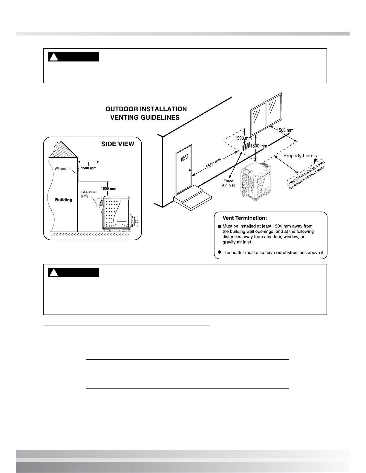
HEATER CLEARANCES – OUTDOOR
If the heater is located under a roof or deck overhang, there
must be at least 1 meter (3 ft.) of clearance between the bottom
of the overhang and the top of the heater exhaust vent, see
Figure 10. If the heater is under a roof or deck overhang, the
space around the heater must be open on three sides.
For minimum exhaust vent clearances for building openings,
see below Figure 11.
Orient the heater for convenient access to the water connections
and the gas and electrical connections.
Check local building codes for setback (property line)
requirements.
Figure 9.
SHEET
METAL
BLOCKS
Hollow masonry blocks, not less than 100 mm thick, (laid with ends
unsealed and joints matched for air circulation). Cover blocks with
0.75 mm (min.) galvanized sheet metal.
152.4 mm Min.
152.4 mm Min.
BASE FOR USE ON
COMBUSTIBLE FLOORS
Figure 8.
1 meter (3 ft.) or more
Figure 10.
I pg 18
Section 3. Installation
INDOOR VENTING — General Requirements
NOTE: REMOVE OR COVER “OUTDOOR ONLY” LABEL LOCATED ON HEATER OUTSIDE
PANEL WITH “INDOOR INSTALLATION” LABEL (P/N 474275) INCLUDED IN ACCESSORY
BAG (P/N 473607).
If installing the heater next to or near an air conditioning unit or a heat pump, allow a
minimum of 91.4 cm (36 in.) between the air conditioning unit and the heater.
!
CAUTION
Risk of fire and explosion. Do not spray aerosols in the vicinity of the heater while it is in
operation. Chemicals should not be stored near the heater installation. Combustion air can
be contaminated by corrosive chemical fumes which can damage the heater and will void
the warranty.
!
WARNING
If you are considering connecting this heater to a pre-existing vent system, make sure that the
vent system meets the appropriate venting requirements as given in this manual on pages 17-
28. If not, replace the vent system. DO NOT use a draft hood with this heater. The Turbotemp
heaters are capable of a 270-degree discharge rotation and with a vent gas temperature less
than 204° C (400° F). The total length of the horizontal run must not exceed the length that is
listed in Table 7, Page 24.
INDOOR INSTALLATION
(SEE INSTALLATION GUIDE FOR CORRECT PLACEMENT OF THIS LABEL)
P/N 474275
Figure 11.
 Loading...