

www.waterco.com
WARNING
!
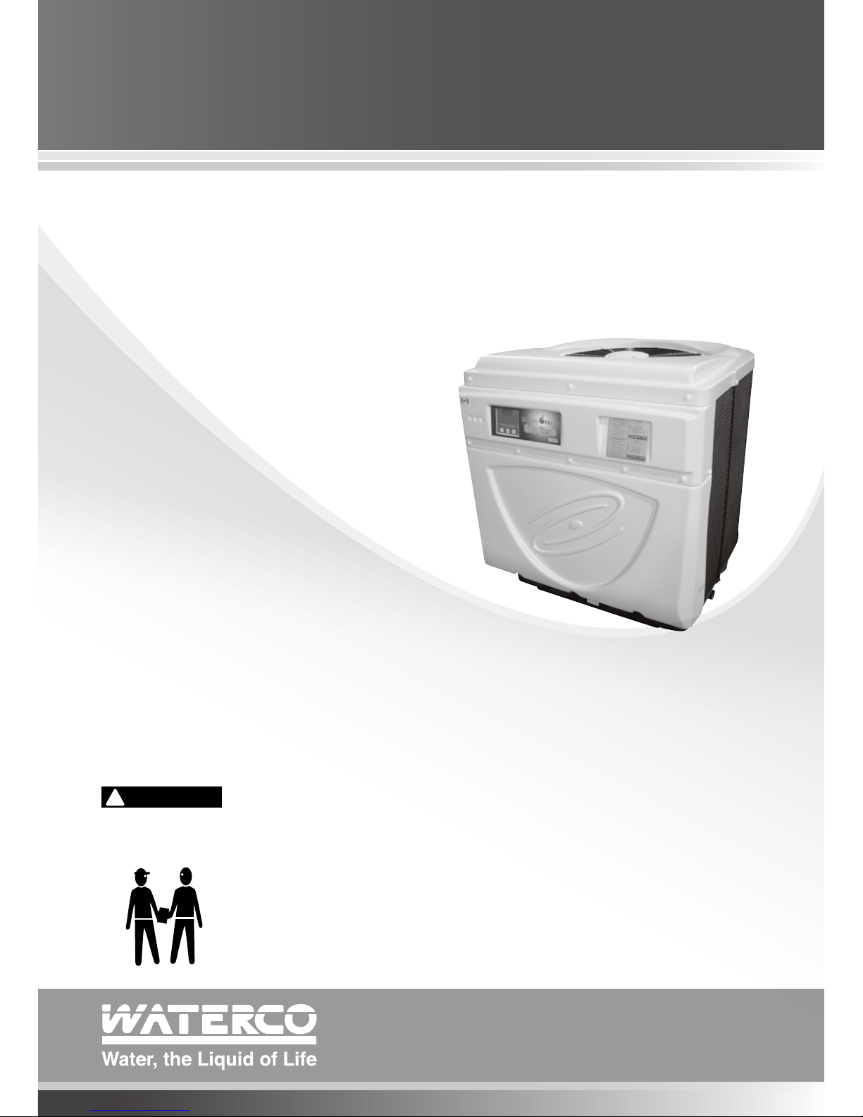
WATERCO POOL HEAT PUMP
User and
Care Guide Manual
This equipment must be installed and serviced by a qualified technician.
Improper installation can create electrical hazards which could result in property
damage, serious injury or death. Improper installation will void the warranty.
Notice to Installer
This manual contains important information about the installation, operation and
safe use of this product. Once the product has been installed this manual must
be given to the owner/operator of this equipment.

Table of
A NOTE TO YOU ---------------------------------- 02
GENERAL SAFETY ------------------------------- 03
INSTRUCTIONS
INSTALLATION INSTRUCTIONS ---------------- 05
Location --------------------------------------- 05
Water Piping ---------------------------------- 07
Plumbing Diagram --------------------------- 07
Electrical -------------------------------------- 08
Electrical Connection ------------------------ 08
Bonding --------------------------------------- 09
Bonding Diagram ----------------------------- 09
OPERATION OF YOUR POOL HEAT PUMP ---- 10
Initial Heating ---------------------------------- 10
Pool Heat Pump Running Time -------------- 10
Pool Solar Blanket ---------------------------- 11
Defrost Cycle ---------------------------------- 11
Electronic Control with Diagnostics ------ 11
and Reversible (XLR) Electronic
Control with Diagnostics
To Start The Pool Heat Pump ---------------- 12
To Stop The Pool Heat Pump ---------------- 12
To Check and Adjust Temperature Settings - 12
Specic Functioning of Your Reversible ----- 13
Electronic Control with Diagnostics
Temperature Calibration ---------------------- 14
Operation of Multi Function Electronic --- 15
Control Panel
To Start the Pool Heat Pump ---------------- 15
To Stop the Pool Heat Pump ---------------- 15
To Raise or Lower Desired Water ------------ 16
Temperature
To Change Display from Farenheit ---------- 16
to Celcius
Defrost for Electroheat Subzero ------------- 16
Electrical connection of an automatic ------ 17
mode for the pool and spa (Smart Energy
model only)
How to Program The Multi Function -------- 18
Electronic Control Timer to Control Your
Pool Pump Filtration
How to Program The Timer ------------------ 18
How to Stop The Timer ---------------------- 18
Electrical connection required to use ------- 18
the integrated pool water pump timer
of your pool heat pump
Protection Devices ---------------------------- 20
Adjustment of The Bypass Valves ----------- 20
MAINTENANCE OF YOUR POOL HEAT PUMP- 21
Winterizing ------------------------------------------ 21
TROUBLESHOOTING ----------------------------- 22
Nothing Is Working and The ----------------- 22
Electronic Control Does Not Operate
Nothing Is Working But The Electronic ------ 23
Control Temperature Displays Digits
or a Code
Fan Doesn’t Work (The Fan Blades ---------- 23
Are Not Moving)
Fan Blades Turn, But Compressor ----------- 23
Is Not Functioning
Compressor Starts and Stops --------------- 24
There Is Water Around The Pool Heat Pump- 24
Pool Heat Pump Has Ice Formed ------------ 25
On The Evaporator Coil
Pool Heat Pump Is Functioning, But Does -- 26
Not Reach The Desired Temperature Setting
Analysis Chart --------------------------------- 27
Circuit Breaker Trips -------------------------- 27
The Pool Heat Pump Is Noisy ---------------- 28
The Temperature Shown On Pool Heat ----- 28
Pump Is Not The Same That Is
Shown By The Pool Thermometer
Service Analyser Codes --------------------- 29
WARRANTY ---------------------------------------- 33

A NOTE TO YOU
Congratulations!
You have made an excellent choice! The Waterco pool heat pump will give you unique
comfort at low-price.
Using the latest technology in heat capture, the Waterco pool heat pump converts the
energy released by the sun and transfers it efciently to your swimming pool.
During certain periods it may be necessary to operate your pool heat pump continuously
however this should not be of concern as your Waterco pool heat pump can heat up
your pool 80% more economically than the fossil fuel heating or heaters with electric
elements.Waterco pool heat pumps are designed specically to heat up your swimming
pool economically.
To appreciate the benets that the product will bring you, make sure to operate the unit
when the atmospheric conditions specied in this document are present in addition of
using a solar blanket to minimize heat loss. Pools not covered with a solar blanket lose 2 to
3 times more heat, regardless of types of heating!
I pg 02
Pool Heat Pump

Record your model’s information.
Keep this manual and your original proof of purchase receipt for warranty and future
reference.
On the base of your pool heat pump is a name plate which contains information such as
model number, serial number and electrical information.
Please write these down below and have them handy incase of a service call request.
Model Number _______________________________________________________________
Serial Number _______________________________________________________________
Purchase Date _______________________________________________________________
Dealer Name _______________________________________________________________
Dealer Address _______________________________________________________________
Dealer Phone _______________________________________________________________
We have provided important safety messages in this manual and on your pool
heat pump. Always read and obey all safety messages.
This is the safety alert symbol.
This symbol alerts you to hazards that can kill or hurt you and others.
This is a very important label.
This symbol alerts you of instructions that MUST be followed properly in order to
ensure that your warranty will not be voided.
These are instructions that must be respected in order to protect the user’s health
and to ensure that your warranty will not be voided.
IMPORTANT
!
VITAL
WARNING
!
GENERAL SAFETY INSTRUCTIONS
To nd detailed product information, the location of the nearest dealer or to register your
pool heat pump please visit our website www.waterco.com and select your location.
All electrical connections must be carried out by a qualied electrician, according to the
local electrical codes. Always cut off the unit’s main power whenever the access panel is
open or removed. It is strongly recommended that the pool heat pump is installed outdoors
(unless approved by the manufacturer), while respecting the minimal clearances needed for
proper operation and heating. Please refer to “Location” on the following page
MAKE SURE THE INSTALLATION WAS CARRIED OUT ACCORDING TO THE
INSTRUCTIONS OF THIS MANUAL. SEE “INSTALLATION” SECTION.
MAKE SURE YOUR POOL HEAT PUMP WAS PROPERLY GROUNDED AND BONDED.
SEE “BONDING” AND “BONDING DIAGRAM” SECTIONS.
BEFORE ASKING FOR ASSISTANCE OR SERVICE, PLEASE READ CAREFULLY THE
SECTIONS ON “TROUBLESHOOTING ” AND “WARRANTY”.
!
VITAL
I pg 04
Pool Heat Pump
Proper pool chemistry is vital to the longevity of your pool heat pump. Pay particular
attention to the total alkalinity and total dissolved solids. It is highly recommended that
you have your pool chemistry checked often by an outside independent pool store. Your
pool water chemistry must be maintained at all times as shown in the table below to prevent
damage to your pool heat pump.
WARNING
!
IMPORTANT
DESCRIPTION NORMAL RANGE* VERIFY
PH Level
Chlorine Concentration
Total Alkalinity
Total Dissolved Solids
Calcium Hardness
7.4 to 7.8
1.0 to 4.0 PPM
100 to 120 PPM
below 1800 PPM Reg. Pool
below 3500 PPM Salt. Pool
200 to 300 PPM
1 per week
1 per 2-3 days
1 per 2-3 weeks
1 per month
1 per month
1 per month
* Warranty can be voided if not maintained within these ranges.
USAGE OF CHEMICAL PRODUCTS
Never add liquid chlorine, granular chlorine, or slow dissolving tablets/ pucks into the
skimmer basket. This high concentration of chemicals should be avoided.
Water quality standards that must be strictly adhered to*:
GENERAL SAFETY INSTRUCTIONS

GENERAL SAFETY INSTRUCTIONS
DO NOT DEPRIVE YOUR POOL HEAT PUMP OF WATER FLOW FOR MORE THAN
24 HOURS WITHOUT DRAINING IT. Make sure you leave the bypass valves as
shown in Figure 1.
At the end of each season, when the pool heat pump is no longer in use, and proper
pool water chemistry is not maintained, it should be disconnected from the water line and
drained to prevent any possible corrosion or damage to the pool heat pump. Refer to Figure
1 below or interizing procedure (page 21).
INSTALLATION INSTRUCTIONS
Location
In order to gain maximum efciency please follow the instructions when deciding where to
position your pool heat pump. It is also important to allow clearances for future service and
maintenance procedures.
The unit is designed for outdoor installation and should not be installed in a totally enclosed
area such as a shed, garage, etc., unless ventilation is provided to ensure adequate
air exchange for proper operation. Re-circulation of cold discharged air back into the
evaporator coil will greatly reduce unit’s heating capacity and efciency.
Pool heat pump Pool heat pump
OUT
IN
OUT
IN
When your valves position are as
shown on Figure 1, the water is
bypassing the pool heat pump.
Figure 1
When your valves position are as
shown on Figure 2, the water is going
through the pool heat pump.
Figure 2
The valves shown above may be different to the ones installed on your system.
Please ensure you understand how your bypass valve operates.
I pg 06
Pool Heat Pump
INSTALLATION INSTRUCTIONS
Location
The unit should be located as close as practically possible to the existing pool pump and
lter to minimize water piping. The use of 90 degree bends and short radius elbows in the
water piping should be kept to a minimum.
Mount the unit on a sturdy base, preferably a concrete slab or blocks. The base should be
completely isolated from the building foundation or wall to prevent the possibility of sound
or vibration transmission into the building. The size of the base should not be less than the
base of the pool heat pump.
Your pool heat pump will accumulate condensed water (approx. 1 to 1.5 gallon or 4
to 6 litres per hour), therefore causing water to drain out of the unit base. In order to
avoid water accumulation, you may use decorative rocks around the concrete slab or
a basin under the unit. (Please note this is a normal characteristic of a pool heat pump and
not a service or warranty issue.)
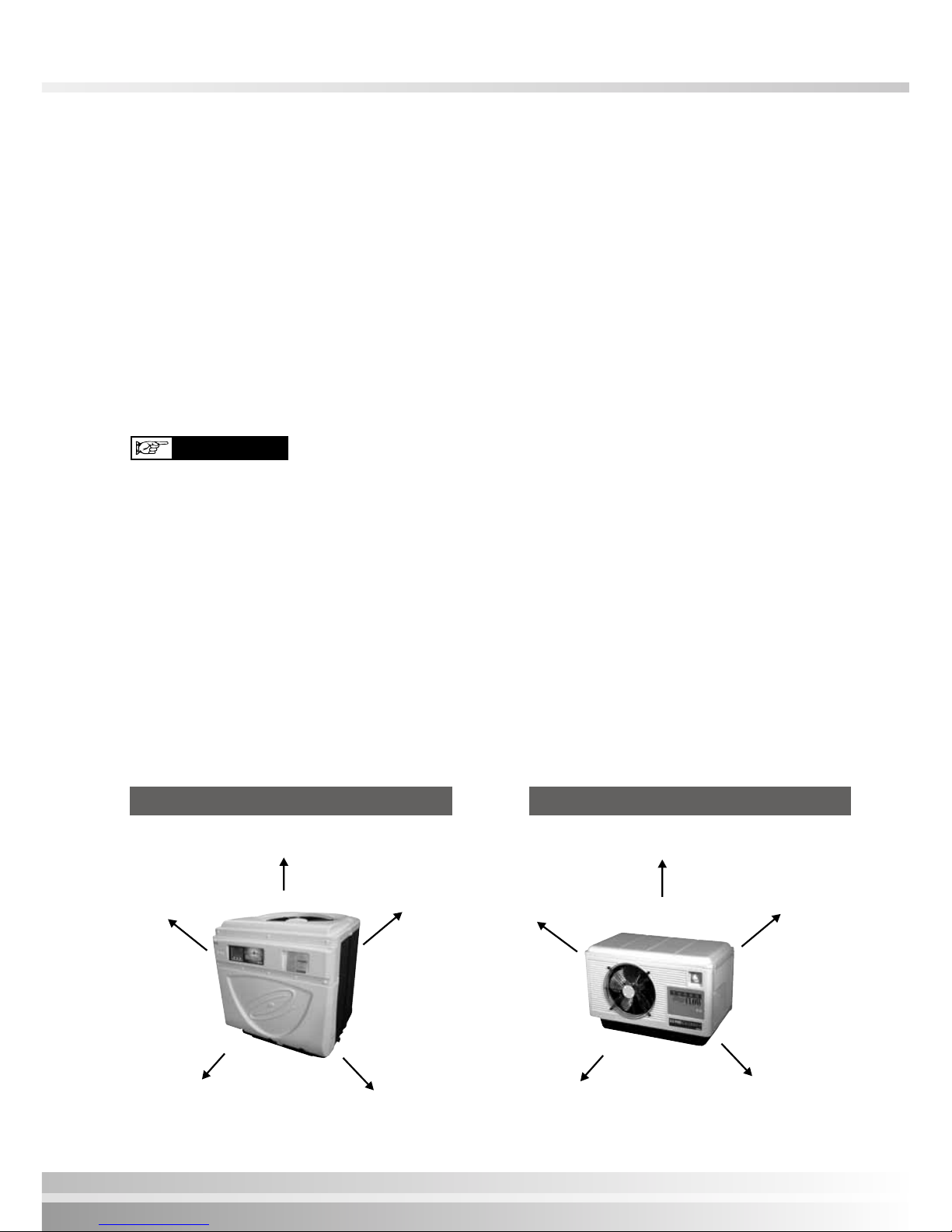
Air is pulled through the evaporator coil and discharged through the top or front grill.
Clearances should be allowed in front and around the unit for unrestricted air
discharge and service access. See Figure 1 and Figure 2.
Re-circulation of cold discharged air back into the evaporator coil will greatly reduce
unit’s heating capacity and efficiency.
IMPORTANT
No obstruction above
24” to 36”
(60 to 91 cm) min.
24” to 36”
(60 to 91 cm) min.
24” (60 cm) min.
24” to 36”
(60 to 91 cm) min.
24” to 36” (60 to 91 cm) min.
5’ (1.5m) min.
18” (46 cm) min.
18” (46 cm) min.
24” (60 cm) min.
Top Discharge Models Side Discharge Models
Figure 1 Figure 2

INSTALLATION INSTRUCTIONS
Water Piping
The following piping sequence must be followed without exception: 1-pool pump 2-lter
3-pool heat pump 4 chlorinator (when installed). Rigid PVC piping is recommended, all
joints should be glued with PVC glue. If rigid PVC is not available, you can use soft or
exible piping with stainless steel clamps. When the piping installation is complete, operate
the pool pump and check the system for leaks. Then check the lter pressure gauge to see
that excessive pump head pressure is not indicated. NOTE: Units are designed to operate
with a minimum water circulation of 132 LPM/35 GPM.
NOTE: A bypass kit is strongly recommended and should be installed for adjustment of
water flow and ease of service.
1. Either a 1/3 pound check valve or a loop MUST be installed between the pool heat
pump and any automatic chlorinator to prevent highly chlorine concentrated water from
owing back to the pool heat pump when the pool pump is not running.
2. Units which are located below the water level of the swimming pool may require the
pressure switch to be adjusted.
This can be checked by the following method:
i) switch on the water pump and pool heat pump.
ii) while the pool heat pump is running switch “OFF” the water pump.
If the pool heat pump shuts down automatically no further action is required.
If the heat pump continues to run you will need to have a qualied technician adjust the
water pressure switch. For further information please, contact Waterco.
!
VITAL
Plumbing connections to
the heater must be made by
hand only as it may break
the water Inlet or Outlet
connections.
IMPORTANT
Plumbing Diagram
Hookup

I pg 08
Pool Heat Pump
IMPORTANT
Electrical
To ensure your safety and ensure the adequate functioning of your pool heat pump, all
electrical work should be performed by a fully qualified and licensed electrician in
accordance with local electrical codes.
An adequate circuit breaker and copper wiring must be used. This information is available
on the name plate of the pool heat pump. It may be necessary to install a ground circuit
breaker.
THE POOL HEAT PUMP MUST BE DISCONNECTED BEFORE
OPENING THE ACCESS PANEL.
WARNING
!
Electrical Connection
Standard 60 Hz power supply : 208/240 v - 60Hz-1 phase
Standard 50 Hz power supply : 208/240 v - 50Hz-1 phase
3 phase power supply : 200/230 v - 50/60 Hz - 3 phase
380/420 v - 50/60 Hz - 3 phase
Breaker Size
Please consult name plate on the base or the side of your pool heat pump for running
amperage and required breaker size.
Electrical Wire Size
Please consult a qualied and licensed electrician.
WARNING
!
The power cable ground must be connected to the electrical panel and to the ground
lug of the pool heat pump. An improper installation may be a potential cause of fire,
electrical shock or injury.
INSTALLATION INSTRUCTIONS

Because all metals have different electrical potentials, ALL metal and electrical
components of the pool system MUST be bonded together. This includes the metal
framework of the pool, the light, the pump, the lter (if metal), the pool heat pump, any
automatic chlorine generator, and any other metal or electrical equipment bonded to your
pool.
On some older pools, this substructure bond wire may not exist. In these cases, a 3 - 4
foot solid copper rod must be driven into the ground near equipment; all electric and metal
components must be bonded to each other, and to the copper rod. Warranty will be voided
if system is not properly bonded.
CAUTION: It is recommended when using automatic chlorinators , to ensure that they
are properly installed and bonded. Some of these systems may leak stray voltage and
currents into the water causing severe electrolysis. This dramatically shortens the life
of the pool heat pump and will void the warranty.
NOTE: Bonding to pool pump is not required to above ground pool pumps but all
other equipment must be bonded.
!
VITAL
Bonding
!
VITAL
Bonding Diagram
Pool House
Breaker Box
Power Supply
and Grounding
Wires Conduits
Chlorine
Generator
Heat Pump
Need bounding
if it is a metal lter
Pool Pump
If Pool Bonding Wire does
not exist, then a 3’ to
4’ Copper Rod must be
driven into the ground and
equipment bonded to it.
Light
3’ to 4’ Copper Rod
Bonding Wires
Pool Bonding Wire
INSTALLATION INSTRUCTIONS
I pg 10Pool Heat Pump
OPERATION OF YOUR POOL HEAT PUMP
Initial Heating
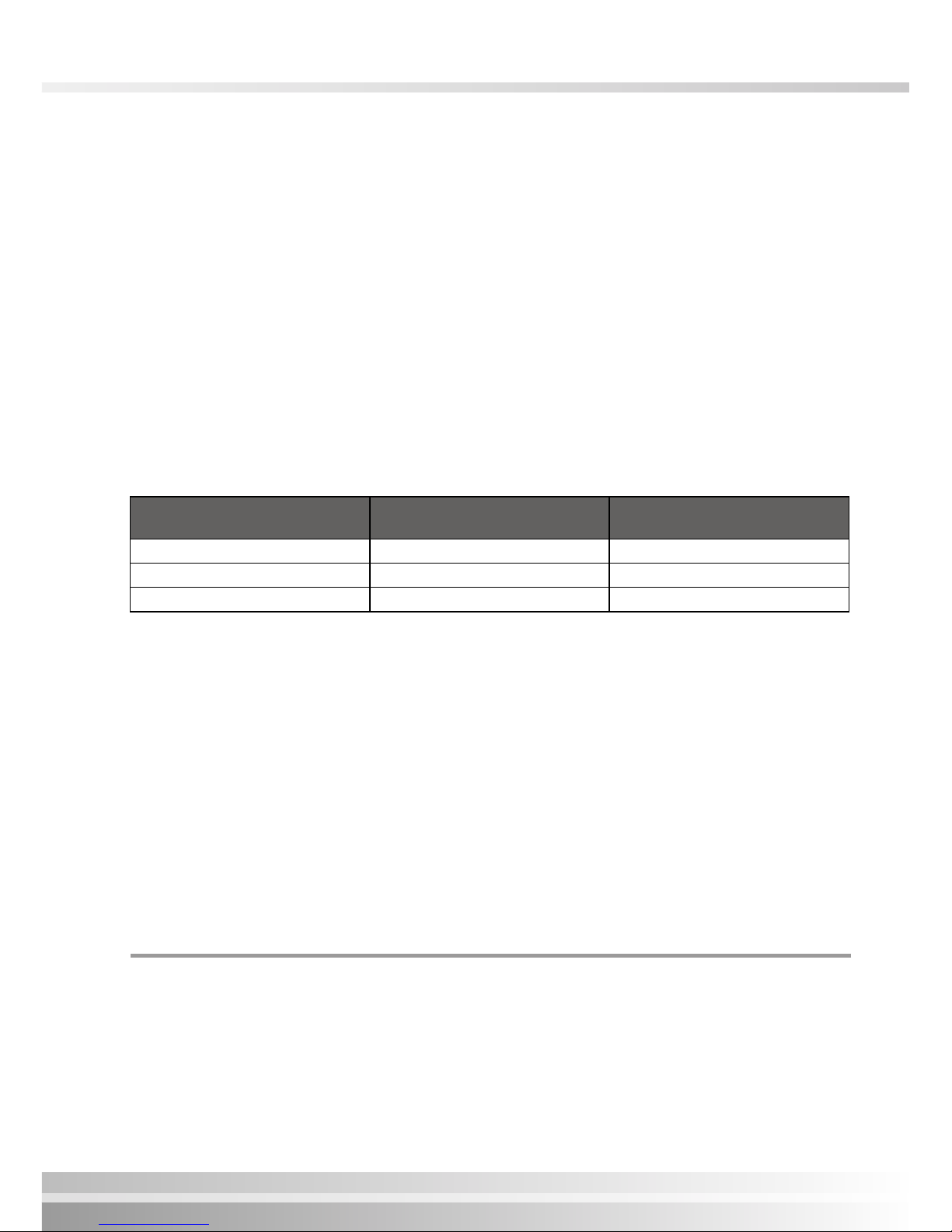
Atmospheric conditions as well as the pool water temperature should not be below the
minimum operating temperatures as stated below in order to obtain efciency and avoid
codes from appearing on the electronic control temperature display; these codes are not
generally a problem with the pool heat pump at these conditions and is not covered by the
warranty.
If temperatures are below the minimum temperatures listed the pool heat pump should not
be operated and must be switched off.
For Electroheat SubZero and Reversible (XLR) units, they will automatically stop without
human intervention.
Model
Atmospheric conditions
must be above
Pool water temperature
must be above
Electroheat SubZero 32°F (0°C) 50°F (10°C)
Reversible (XLR) 43°F (6°C) 65°F (18°C)
All others 52°F (11°C) 65°F (18°C)
The speed of heating is dependent upon ve basic factors:
1. Size of the pool.
2. How many degrees the water is to be heated.
3. Ambient air temperature - the warmer the air, the less time required to heat.
4. Use of a solar blanket .
5. The size of the pool heat pump.
To achieve initial heating, your pool heat pump and the pool pump may work up to 24 hours
per day until desired temperature is achieved. The initial heating time may vary depending
upon the above ve factors. After initial heating, operating time may be reduced to match
daily heat loss.
Pool Heat Pump Running Time
Most units should be sized to operate during the pool ltering cycle time of 8-12 hours
daily, providing an even, steady ow of warm water. On warmer days the pool heat pump
will run less because the heat loss will be less. Pool heat pumps are able to operate 24
hours per day when necessary.

Electronic control with diagnostics and Reversible
(XLR) electronic control with diagnostics
Pool Solar Blanket
A pool solar blanket should be used whenever possible. Blankets minimize heat loss and
conserve heat in your pool. Un-blanketed pool lose 2-3 times more heat than a blanketed
pool
Defrost Cycle
When any of the following conditions occur the electronic control of your unit will activate
a defrost mode until all frost from the evaporator has melted. Condensation of water on the
evaporator coil tends to frost up quicker when the following occur.
1. When atomospheric conditions are as stated above;
2. When the evaporator is dirty;
3. When installation clearances are not respected.
Defrost is activated for between 3 to 20 minutes.
Electronic Control
with diagnostics
Reversible (XLR) electronic control
with diagnostics

I pg 12
Pool Heat Pump
To Start The Pool Heat Pump
Press the button on the electronic control ON/OFF to start the pool heat pump. The
temperature display will show the pool water temperature owing in your pool heat pump
and the fan motor starts (fan blade turns) but the compressor does not start.
The temperature display ashes until the compressor starts and when the timer will complete
its cycle of 3 to 5 minutes. After 5 minutes, the compressor starts and the temperature on
the display stops ashing.
You can now program the desired temperature for the pool water.
To Stop The Pool Heat Pump
The pool heat pump can be stopped by pressing the ON/OFF button once.
To Check and Adjust Temperature Settings
To program the desired water temperature, press BOTH the UP and DOWN arrow keys at
the same time until the temperature degree displays change degree, then release them.
Press the UP arrow or DOWN arrow to program the desired temperature. The temperature
setting will automatically ash and will be saved. The display temperature will be revert
back to the pool water temperature when all keys have remained untouched for 5 seconds.
To change the temperature display from Fahrneheit (˚F) to Celcius (˚C). Press, the button
˚C/˚F. The led below the ˚F or ˚C will be lit to indicate the current selection.
Note: The pool heat pump will cut out at once when the programmed temperature has
been reached.

Electronic Control
with diagnostics
Reversible (XLR) electronic control
with diagnostics
In addition to controlling the temperature of the water, this electronic control informs you
on the operation of your pool heat pump or any faults that may arise by displaying codes
on the temperature display.
When the unit is in defrost mode the code “DEF” is dispalyed on the temperature display.
This under normal conditions is not considered to be a fault.
Specific functioning of your reversible electronic
control with diagnostics
During the defrost cycle, the fan motor stops working and the hot gas is injected into the
evaporator to melt the frost. However, when the unit makes 4 cycles (heating and defrost)
consecutive within 1-hour, the unit goes into protection mode to avoid inefcient use of
electricity. These frequent defrost cycle’s mean that the conditions of ambient temperature
and humidity do not allow to heat your pool water. The DEF code and the water temperature
will be displayed alternately on the electronic control. Refer to the section titled ¨ Service
Analyser Codes ¨ to validate what you should do.
Codes
If a code appears on the electronic control refer to Service Analyser codes (all models) on
page 29.

I pg 14
Pool Heat Pump
Temperature Calibration
It is possible to have a temperature variation between the water in the swimming pool and
the reading of the pool heat pump temperature probe (sensor). Example:if the water in the
pool is 26º C (80º F) and the heat pump electronic control displays 24ºC (76º F).
To calibrate this variation, perform the following procedure:
1. With the use of an accurate thermometer read the pool water temperature (e.g: 26˚C).
2. Read the temperature displayed on the pool heat pump electronic control (eg: 24˚C).
3. To determine the differential subtract the pool water temperature from the pool heat
pump displayed temperature, 26 - 24 = 2˚C. Therefore we must compensate for the 2˚C
variation.
4. Press BOTH the UP and DOWN arrow keys until the programmed temperature is
displayed ( the temperature you have previously set) then release both buttons.
5. Press the ON/OFF button and release.
6. Using the UP and DOWN arrows, enter the calibration value, (2˚C). In this case, by
pressing the UP arrow twice.
7. After 5 seconds when all the buttons have remained untouched , the display temperature
will show the pool water temperature as per your thermometer. If this is the case the
calibration process was successful.

Operation of Multi Function Electronic
Control Panel
The temperature display of the electronic control panel is factory set to show pool water
temperature in degrees FAHRENHEIT. See “To select temperature in ˚C or ˚F” section on
the following page.
To Start The Pool Heat Pump
When the pool heat pump is turned “ON” or after a power shut down, the panel lights up
and either indicates “OFF” or the temperature of the pool water circulating inside the pool
heat pump.
When the unit is rst turned on and water is owing, the fan motor will start (blades will
turn) followed by the compressor 3 to 5 minutes later. ( the compressor and fan may start
together when the unit has automatically cycled off for a period of time and then restarts)
To Stop The Pool Heat Pump
The pool heat pump can be stopped by switching off the electrical power supply or by
setting the desired water temperature setting to below 60˚F (15˚C).
Actual temperature and setting display
Pool Mode
Compressor running
Spa Mode
To toggle
between
functions
To lower desired temperature or
to change settings
To raise desired temperature or
to change settings

To Raise or Lower Desired Water Temperature
(Pool or Spa Mode)
The Multi function electronic control has the capability of memorizing two different
programmed temperature settings as follows:
For POOL the maximum is 95°F (35°C) and for SPA the maximum is 104°F (40°C)
To access the pool (POL) mode or spa (SPA) mode, press the SET key until you see P-S
and then press the UP or DOWN key to switch to POL or SPA .
Push the SET key again to enter into the desired heating temperature mode.
Press the UP or DOWN arrow to increase or decrease the temperature setting by one degree
at a time. Once the heating mode is programmed, it will be displayed for approximately 5
seconds; then the temperature display will return to the actual pool water temperature. The
light on the right side of the display indicates the chosen heating mode .
To change display from Farenheit to Celcius
1. Press and release the SET key until F-C appears on the temperature display.
2. Whilst F-C is still on the display Press and release the UP or DOWN arrow key until C
is displayed.
3. Release all keys and the control will now be set for Celcius. (do not press any other keys
for 5 seconds)
To go back to Farenheit follow the same instructions above, however when you are at step
2, F will need to be shown on the display before releasing all keys
Defrost for Electroheat SubZero
During the defrost cycle, the fan motor stops working and the hot gas is injected into the
evaporator to melt the frost. However, when the pool heat pump makes 5 consecutive
cycles (heating and defrost) in less than 15 minutes, the unit goes into protection mode to
avoid inefcient use of electricity. These frequent defrost cycle’s mean that the conditions
of ambient temperature and humidity do not allow to heat your pool water. The FS4 code
will be displayed on the electronic control. Refer to the section titled ¨ Service Analyser
Codes ¨ to validate what you should do.
I pg 16
Pool Heat Pump

Electrical connection of an automatic mode for the
pool and spa (for Smart Energy model only)
The Multi Function electronic control has the ability to switch from POOL to SPA mode
automatically .This function is used when warm water is directed towards the SPA.
Activation is carried out by using an external water pressure switch connected to the SPA
water line. This connection must be done by a qualied technician.
When the electronic control of the pool
heat pump is located inside the electrical
box the 2 wires coming from the pressure switch
connected on the water piping going to the SPA
(as shown on the right) must be connected at the
boundaries of the electronic control of the pool
heat pump.
When the electronic control of the pool
heat pump is mounted on the front panel
of the unit: The Orange and Orange-Black wires located inside the electric box junction
of the pool heat pump must be connected to the water pressure switch connected on the
water piping going to the SPA.
Electrical connection to an automation system to the pool (for Smart
Energy model only) It is possible to carry out the connection of the Multi Function
electronic control to an automation system for models P4 or P8. This type of connection
must be done by a qualified technician to ensure that your warranty will not be voided.
For automation system operation, you will need to set the SPA temperature to maximum
40˚C (104°F) and the POOL setting to ‘‘OFF’’, so that when the automation system calls for
heat; it will activate the SPA mode and starts the pool heat pump.
Note: When calling for a service technician, you will have to mention the installation of this
type of automation system.
Pool/Spa
WS DS AS P/S
HP LP
SPR2
FLO COMP
AC F1 F2 F3
PUM P12120
~~
Codes
For codes refer to the section titled “Service Analyser codes”.

I pg 18
Pool Heat Pump
How to program the Multi Function electronic
control timer to control your pool pump filtration
Note: This option is available only on the Smart Energy pool heat pump model.
The Multi Function electronic control includes an adjustable internal timer, which allows to
control the ltration time of the pool pump. This timer allows 6 cycles of filtration during
a day.
Example:
Desired time of ltration: 3 hours / day = 180 minutes / day
Calculation: 180 minutes/day DIVIDED by 6 cycles of ltration/day = 30
Finally, your pool pump will work 6 times a day during 30 minutes; however, if the water
temperature programmed has not reached, the pool pump will work until it reaches the
programmed water temperature.
How to program the timer
1. Press the SET key until FIL is displayed;
2. If you want the pool pump to work continuously; press the up or down arrow until ON
is displayed;
3. If you want the pool pump to work during a specic period, press the up or down
arrow until the number of hours per day of the ltration that you desire is displayed (for
example: you would like 3 hours/day, the number 3 must appear on the Multi Function
electronic control).
Note: This type of programming FAVOURS the maintaining of the programmed water
temperature rather than the time of ltration.
How to stop the timer
1. Press the SET key until the Multi Function electronic control displays FIL;
If you do not want to use the timer included in the Multi Function control, press the up or
down arrow until OFF is displayed.

Electrical connection required to use the integrated
pool water pump timer of your pool heat pump.
Note: This option is available only for Smart Energy model.
If you wish to use the integrated timer of your pool heat pump; you must warn your
electrician at the time of installation. All electrical work should be performed by a fully
qualified and licensed electrician in accordance with local electrical codes. The pool
pump MUST not consume more than 16 amps.
NOTE: The junction box of the timer does not provide power for the swimming pool pump,
but instead switches the power (which is fed from another source) on and off to control
the pump. An adequate circuit breaker dedicated to the swimming pool pump must be
installed with copper wiring used in order for the bencial functions of the timer. It may be
neccessary to install a ground fault circuit breaker.
IMPORTANT
Use the junction box at the base of pool heat pump
For model Smart Energy System Only
Wiring colour codes are:
Green : Ground
Black : Input L1
White : Input L2
Orange : Output T1
Red : Output T2
Junction Box
for the timer
Pool Pump Beaker
Pool Pump

I pg 20
Pool Heat Pump
Protection devices
The integrity and performance of your pool heat pump and its components are protected
by internal safety controls. In normal use, your Waterco unit should never reach the thermal
protection level. However, if it should happen, you should identify the stated code on the
temparature display and refer to Service Analyser codes.
Adjustment Of The Bypass Valves
The adjustment may vary according to pool pump size and ambient temperatures.
ATTENTION: IT IS VERY IMPORTANT THAT THE BYPASS VALVES ARE SET AS DESCRIBED
BELOW FOR THE CORRECT FUNCTION OF YOUR POOL HEAT PUMP
When the pool water
temperature is
between 65°F (18°C) and 70°F
(21°C) please adjust the bypass
valve as shown. Approx. 60%
of the water is circulating in
the unit.
OPEN
VALVE POSITION
HEAT
PUMP
INLET
OULET
OPEN
VALVE POSITION
HEAT
PUMP
INLET
OULET
When the pool water
temperature is between
70°F (21°C) and 78°F (26°C)
please adjust the bypass valve
as shown. Approx. 80% of the
water is circulating in the unit.
VALVE POSITION
CLOSED
HEAT
PUMP
INLET
OULET
When the pool water
temperature is above
79°F (26°C) please close the
bypass valve
as shown. 100% of the water
is circulating in the unit.

MAINTENANCE OF YOUR POOL HEAT PUMP
Waterco pool heat pumps have been specically engineered to give you years of satisfaction
and enjoyment in the pool.
CABINET CLEANING
To clean the plastic surfaces use mild soapy water and a soft clean cloth. Never use
solvents or abrasives.
CLEANING EVAPORATOR
it is vital that the evaporator is kept clean and un-obstructed in order for your pool heat
pump to have better efciency and avoid problems which may void your warranty. The dirt
collected in the evaporator can be removed with a gentle water spray and the use of a soft
brush. Be careful not to damage the aluminum ns.
Winterizing
If the pool heat pump is stored in a place where the temperature drops below the freezing
point of 0˚C (32°F); it is mandatory that the water accumulated in the pool heat pump
be drained completely before freezing weather prevails. Improper winterizing may
damage the pool heat pump and will void the warranty.
• Turnthepoolheatpump“OFF”.
• Turnthepoolheatpumpbreaker“OFF”.
• ThewaterpipingMUST be disconnected to drain the pool heat pump’s heat exchanger
in preparation for winter.
• Once the piping is disconnected, the pool heat pump’s heat exchanger MUST be
emptied; the use of a water vacuum cleaner is strongly recommended or if you do not
have this tool you can tilt the unit (75˚) until all the water is out.
• Itis recommended that poolheatpump’sheatexchangeris rinsed outwitha gentle
water spray at the inlet and outlet water connections of the pool heat pump and then
drain the heat exchanger again.
• Withthehelpof2poolreturnwinterplugs,blockthewaterInletandOutletconnections
to prevent access by vermin.
• Cleanthedrainageholeslocatedatthebottomofthebaseoftheunit.
• Unitmaybecoveredforthewinter.
• Itisalsopossibletollthe heat exchanger withpoolanti-freeze,but ensurethat the
antifreeze contains an elevated pH to prevent corrosion. This is optional and requires
appropriate hardware.
!
VITAL

I pg 22Pool Heat Pump
TROUBLESHOOTING
Please make sure you carefully read the troubleshooting section in order to avoid
unnecessary service call fees.
Atmospheric conditions as well as the pool water temperature should not be below the
minimum operating temperatures as stated below in order to obtain efciency and avoid
codes from appearing on the electronic control temperature display ; these codes are not
generally a problem with the pool heat pump at these conditions and it is not covered by
the warranty.
If temperatures are below the minimum temperatures listed the pool heat pump should not
be operated and must be switched off.
For Electroheat SubZero and Reversible (XLR) units, they will automatically stop without
human intervention.
Nothing is working and the electronic control does
not operate
1. Make sure the circuit-breaker has not tripped and/or that the fuses are not burn out;
**Take note that only an electrician can verify if the circuit breaker is defective; if
this is the case, repairs will not be covered under the warranty.
2. For three phase models, this situation could occur when phases are not in the
appropriate order. The green led light on the front panel will not light up.
Please have a qualied electrician swap over two of the incoming phase wires.
IMPORTANT
Model
Atmospheric conditions
must be above
Pool water temperature
must be above
Electroheat SubZero 32°F (0°C) 50°F (10°C)
Reversible (XLR) 43°F (6°C) 65°F (18°C)
All others 52°F (11°C) 65°F (18°C)
If you made the purchase of equipment not included with the Waterco pool heat pump,
make sure that the equipment was properly installed. If the problem is the installation of the
other equipment; Waterco warranty will not apply and you must pay the service call fees.

Nothing is working but the electronic control temperature
displays digits or a code
1. Identify the analyser code that the electronic control displays and refer to the Service
Analyser codes section;
2. If the electronic control displays digits, make sure that the electronic control is
programmed correctly, refer to the Operation of your pool heat pump and reprogram if
necessary.
**Note that this situation could occur when the electrical voltage is not respected
as stated on the pool heat pump name plate. This situation is not covered by the
manufacturer warranty.
Fan doesn’t work (the fan blades are not moving)
1. IMPORTANT: For safety, switch OFF the circuit-breaker.
2. Try to rotate the fan blades of the fan with a rod to see if the motor is jammed or seized
3. If the fan blades do not turn freely leave the unit switched OFF and call for service;
4. If the fan blades turn freely switch ON the circuit breaker and the pool heat pump again.
** Note that your fan motor may have an electrical fault if the blades turn freely when the
unit is switched OFF and does not start when the unit is switched ON.
Fan blades turn, but compressor is not functioning
The pool heat pump has a built in delay timer which prevents the compressor from starting
immediately. The delay can be 3 to 5 minutes in duration after the fan blades have turned.
Furthermore if the unit is in defrost mode the compressor will not start for 3 to 20 minutes.
1. Check that air being discharged from the fan blades is colder than the ambient air. If
the air being discharged by the fan blades is colder, it means that the compressor is
functioning correctly.
2. Turn off the pool heat pump then immediately turn it back on;
3. As soon as the fan blades start turning, wait a minimum of 3-5 minutes. The compressor
should start up after this time and you will be able to identify a different sound made by
the compressor when it starts;

I pg 24
Pool Heat Pump
Compressor starts and stops
1. Check that the unit has been installed correctly (refer to installation procedures).
2. Check that the water inlet and outlet of the unit have not been connected incorrectly.
There is water around the pool heat pump
It is a normal occurrence for water condensation, to be seen running from the unit base.
There will be on average 1 to 1.5 gallons (4 to 6 litres) of condensed water per hour being
discharged from the unit base. In order to avoid water accumulation, you may use decorative
rocks around the concrete slab or a basin under the unit. Be sure that clearances around
the unit are respected.
To test the unit and conrm you have no pool water leaking from the unit perform the
following test which is best performed early in the morning and continuing for the whole
day:
1. Turn off the pool heat pump from the circuit breaker and the pool pump.
2. Open the bypass valve. (refer to drawing on page 5)
3. Close the IN and OUT water valves on the unit.
4. Restart the pool pump. The pool heat pump must remain OFF.
5. When all of the water around the base of the pool heat pump has dried, open the water
IN and water OUT valves on the pool heat pump.
6. Close the bypass valve to allow full water ow through the pool heat pump.
If water is now seen running from the outside of the pool heat pump or inside the pool heat
pump after a short period of time you should call for service. If no water is seen after a short
period of time it would be assumed the water was condensation which is normal.
4. If the compressor is functioning, but shuts off immediately, consult the following section
“ Compressor Starts and Stops “.
5. If the problem persists, call Waterco.

Pool heat pump has ice formed on the evaporator
coil
Atmospheric conditions as well as the pool water temperature should not be below the
minimum operating temperatures as stated below in order to obtain efciency and avoid
codes from appearing on the electronic control temperature display ; these codes are not
generally a problem with the pool heat pump at these conditions and is not covered by the
warranty.
If temperatures are below the minimum temperatures the pool heat pump should not be
operated and must be switched off.
For Electroheat SubZero and Reversible (XLR) units, they will automatically stop without
human intervention.
Model
Atmospheric conditions
must be above
Pool water temperature
must be above
Electroheat SubZero 32°F (0°C) 50°F (10°C)
Reversible (XLR) 43°F (6°C) 65°F (18°C)
All others 52°F (11°C) 65°F (18°C)
1. IMPORTANT: For safety, switch OFF the circuit-breaker.
2. Allow the ice to melt and then inspect the evaporator to ensure it is free of debris and
leaves.
3. If the evaporator is dusty or dirty, clean it with a light spray of water and allow it to dry
(do not use high pressure it may damage the evaporator ns).
4. When the unit is dry, you may switch it back ON from the circuit breaker.
5. Ensure that the clearances around the unit are respected.
6. When the unit has been switched ON ensure the fan motor is working (fan blades will
be turning) while the compressor is operating.
7. If the fan blade does not turn and the compressor is functioning; notify customer
service.
**If the pool heat pump requires service, the owner of the pool heat pump will need to
ensure the unit has been switched OFF to allow any ice to melt prior to any technician
attending.

I pg 26
Pool Heat Pump
Pool heat pump is functioning, but does not reach
the desired temperature setting
Atmospheric conditions as well as the pool water temperature should not be below the
minimum operating temperatures as stated below in order to obtain efciency and avoid
codes from appearing on the electronic control temperature display ; these codes are not
generally a problem with the pool heat pump at these conditions and is not covered by the
warranty.
If temperatures are below the minimum temperatures the pool heat pump should not be
operated and must be switched off.
For Electroheat SubZero and Reversible (XLR) units, they will automatically stop without
human intervention.
Model
Atmospheric conditions
must be above
Pool water temperature
must be above
Electroheat SubZero 32°F (0°C) 50°F (10°C)
Reversible (XLR) 43°F (6°C) 65°F (18°C)
All others 52°F (11°C) 65°F (18°C)
Improper installation may cause this situation and will need to be corrected by the
owner.
1. Make sure the by-pass valves are in the correct positions to ensure sufcient water
ow, insufcient water ow will cause the compressor to shut off early.
2. If you have installed a timer or the pool heat pump is equipped with an integrated timer,
be sure it is programmed to allow the pool pump to work for sufcient time in order to
reach the programmed temperature.
3. Ensure the evaporator is cleaned regularly with a light spray of water and allowed to dry
before re-starting the pool heat pump to avoid premature ice build up on the evaporator.
4. Waterco recommend the use of a solar cover to retain heat in pool water. Pools without
covers lose 2 to 3 times more heat than pools with solar covers.
5. Make sure the electronic control of your pool heat pump has been programmed
correctly;during this test the pool heat pump and water pump must be working
continuously (eg; the desired water temperature must be set correctly).
6. If the unit continually fails to reach the desired water temperature, we suggest
completing the following analysis chart and forwarding it to Waterco in order to avoid
unnecessary service fees.
IMPORTANT

Analysis Chart
Important: Please record all information
for three consecutive days at 12h00
Day 1 Day 2 Day 3
Outside air temperature .................................................................
Weather conditions outside (eg: cloudy, sunny or rainy) ................
Pool water temperature ......................................**Use a pool
thermometer
Pool water temperature ..................................... **use the reading
from the electronic control on the pool heat pump
Important: Please record all information
for three consecutive days at 20h00
Day 1 Day 2 Day 3
Outside air temperature .................................................................
Weather conditions outside (eg: cloudy, sunny or rainy) ................
Pool water temperature ......................................**Use a pool
thermometer
Pool water temperature ..................................... **use the reading
from the electronic control on the pool heat pump
Circuit breaker trips
If you have purchased a remote control (or other equipment), make sure this equipment
was properly installed. If the problem originates from the installation of this equipment,
Waterco’s warranty will not apply and you will have to pay the cost of the service call.
1. The amperage of the circuit breaker AND the electrical wiring must be as the instructions
on the pool heat pump name plate, otherwise notify your installer or electrician to
correct this problem, as this is not covered under the warranty.
2. If the circuit breaker and electrical wiring are as stated, make sure the drains, located
on each side of the base of the pool heat pump are not obstructed.
IMPORTANT

I pg 28
Pool Heat Pump
The pool heat pump is noisy
1. Check the pool heat pump is level and on a solid base to prevent any vibrations issues.
2. Ensure the noise is coming from the pool heat pump, not from other equipment which
will not be covered by the warranty (for example: noise coming from the bypass valve,
pool pump, etc);
3. An improper installation may cause this situation it will need to be corrected by the
owner.
The temperature shown on pool heat pump is not
the same that is shown by the pool thermometer
It is possible to have a temperature variation between the temperature shown on the
electronic control temperature display of the pool heat pump and a pool thermometer
which may be read from different locations. Please refer to the temperature calibration
section in order to adequately recalibrate temperature if required.

Service Analyser Codes (All Models)
Most problems will be detected by the electronic control and a code will appear on the
temperature display. Make sure you follow the Remedy / Action instructions where possible,
before making a service call request and avoid paying unnecessary service call fees. If the
code remains on the display after you have followed the Action / Remedy instructions,
please contact Waterco.
Code Problem - Action / Remedy
dPd, oC2, Sc2 Problem: The intake temperature probe has a loose connection or is
faulty. The probe will need to be checked, and replaced if required.
Action / Remedy: Contact customer service.
FLo, FL3
nFL
Problem: No water ow, not sufcient water ow through the pool
heat pump or the water pressure switch needs to be adjusted or is
defective.
Action / Remedy: If the pool pump is connected to the pool heat
pump make sure the electronic control that runs the pool pump and
pool heat pump are programmed correctly
If the code is still displayed:
- Make sure the pool pump is switched ON;
- Press ¨SET¨ or ¨ON/OFF¨ depending on the model, to restart the
pool heat pump;
- On new installations, ensure the installation instructions were
respected;
- Check that the pool water level is correct, that the pool pump is
lled with water to the rim and that water is owing correctly
through the pool pump to the pool heat pump;
- Check swimming pool and pool pump skimmer baskets and the
drain at the bottom of the pool for obstructions;
- Check the lter cartridges for obstructions (wash or change the
cartridges);
- Carry out a backwash for sand lters and ensure they are working
correctly;
- Ensure that the bypass valves are in the correct positions so that
the water ows adequately;
- Ensure vacuum robot or other cleaners are disconnected so that
the water ows freely.
- Check that there are no leaks on the pool plumbing ( there should
be no air leaks in the pipework);

I pg 30
Pool Heat Pump
Code Problem - Action / Remedy
FS, DEF, FS4 Problem: Normal defrost cycle. The fan blades are turning, but the
compressor has stopped. For Electroheat SubZero and Reversible
model, the fan blades do not turn but the compressor runs.
Action / Remedy: Normal during defrost duration.
Atmospheric conditions as well as the pool water temperature should
not be below the minimum operating temperatures as stated below
in order to obtain efciency and avoid codes from appearing on the
electronic control temperature display ; these codes are not generally
a problem with the pool heat pump at these conditions and is not
covered under warranty.
If temperatures are below the minimum temperatures the pool heat
pump should not be operated and must be switched off.
For Electroheat SubZero and Reversible (XLR) units, they will
automatically stop without human intervention.
Model
Atmospheric
conditions
must be above
Pool water
temperature
must be above
Electroheat SubZero 32°F (0°C) 50°F (10°C)
Reversible (XLR) 43°F (6°C) 65°F (18°C)
All others 52°F (11°C) 65°F (18°C)
For Electroheat SubZero model: If the unit carries out 5 consecutives
defrost cycles every 15 minutes or less, the pool heat pump is then
put into protection mode (FS4). During this mode, the fan blade turns
for 30 minutes in order to cool the evaporator. The pool heat pump
restarts automatically when the external temperature is at: 34˚F (1˚C).
For Reversible (XLR) Model: If the unit performs 4 consecutive cycles
(heating and defrost) within 1-hour, the unit goes into protection
mode and alternately displays the water temperature and the DEF
code. The fan motor runs for 30 minutes to cool the evaporator
and then stops. The compressor is always off. The unit restarts
automatically when the outside temperature is 43°F (6°C) and more.
If the code stays on permanently:
- Ensure the evaporator is clean. If not switch the unit OFF from
the circuit breaker (fuse) and use a garden hose to lightly clean
the evaporator, then allow it to dry before re-starting the pool heat
pump to avoid premature ice build up on the evaporator.
- Ensure installation instructions have been followed, Improper
installation, e.g. no air circulation could lead to the pool heat pump
continually going into defrost mode and the installation will need to
be corrected by the owner.

Code Problem - Action / Remedy
LP, LP3 Problem: Low refrigerant level in the pool heat pump or the low-
pressure safety control is defective.
Atmospheric conditions as well as the pool water temperature should
not be below the minimum operating temperatures as stated below
in order to obtain efciency and avoid codes from appearing on the
electronic control temperature display ; these codes are not generally
a problem with the pool heat pump at these conditions and is not
covered by the warranty.
If temperatures are below the minimum temperatures listed below the
pool heat pump should not be operated and must be switched off.
Model
Atmospheric
conditions
must be above
Pool water
temperature
must be above
Electroheat SubZero 32°F (0°C) 50°F (10°C)
Reversible (XLR) 43°F (6°C) 65°F (18°C)
All others 52°F (11°C) 65°F (18°C)
Action / Remedy:
- If the LP or LP3 code is shown permanently, press ¨SET¨ or ¨ON/
OFF¨ depending of the model you have before to get to next step;
- Ensure the evaporator is clean. If not switch the unit OFF from
the circuit breaker (fuse) and use a garden hose to lightly clean
the evaporator, then allow it to dry before re-starting the pool heat
pump to avoid premature ice build up on the evaporator.
- Ensure installation instructions have been followed. Improper
installation, e.g. no air circulation could lead to the pool heat pump
continually going into LP or LP3 mode and the installation will need
to be corrected by the owner.
HP, HP3 Problem: Low water circulation in the unit or the high-pressure
control is defective. If the HP code is triggered and displayed 3
times; this will cause the pool heat pump to shut down automatically.
The HP3 code will then appear permanently (except for reversible
electronic control with diagnostics).
Note: The pool pump will stop functioning only if the internal time
delay of the pool heat pump is being used.
IMPORTANT: When the code HP3 is permanently displayed, before
performing the steps below, please press the ¨SET¨ button for the
electronic control Multi Function and ¨ON / OFF¨ for the electronic
control with diagnostics and the reversible electronic control with
diagnostics (XLR) and electronic control with diagnostics.

I pg 32
Pool Heat Pump
Code Problem - Action / Remedy
HP, HP3 Action / Remedy: Make sure the water reaches the pool heat pump
and the pool pump is completely lled to the rim. Otherwise:
- Fill the pool pump with water, and check to see if the pipes
between the pool pump and the pool are watertight (there should
be no air intake);
- Check the swimming pool and pool skimmer baskets and the drain
at the bottom of the pool for obstructions;
- Check the lter cartridges for obstructions (wash or change the
cartridges, as the case may be);
- Insure that the bypass valves are in the correct positions so that
the water ows adequately;
- Backwash sand lter (insure that there is a sufcient amount of
sand and verify that it does not have to be changed. Consult a
swimming pool specialist if necessary);
- Make sure the vacuum robot is disconnected so that the water
ows freely.
OFF Problem: The desired water temperature setting programmed is
below 60°F (15°C) for the Multi function electronic control OR the
electronic control with diagnostics is OFF or could be defective.
Action / Remedy: Reprogram the desired water temperature setting
to a higher setting for the electronic control with Multi Function. For
the electronic control with diagnostics and the reversible electronic
control with diagnostics (XLR), press on key ¨ON/OFF¨.
PSD, oC1 &
Sc1
Problem: The water temperature probe has a loose connection or is
faulty. The probe will need to be checked and replaced if required.
Action / Remedy: Contact customer service.
ot Problem: Water temperature is higher than 45°C (113°F) within
the unit (this code is only displayed on the electronic control with
diagnostics).
Action / Remedy:
- Make sure the bypass valves are in the correct positions;
- Proceed to the calibration of the electronic control with diagnotics
and reversible electronic control with diagnostics (XLR).

Before you contact Waterco for assistance or service, please check the “Troubleshooting”
and the information stated in this section. Warranty will only cover manufacturing defects.
All service call requests which are not of this nature must be paid by the purchaser to the
service company authorized by Waterco.
All services will be handled by the authorized service company. Warranty may be voided if
service is not carried out by a service company center authorized by Waterco.
DO NOT return the pool heat pump to your dealer as they do not provide the service work.
Before you contact Waterco for assistance or service, in order to qualify for a warranty
claim, the original purchaser must have the model name and serial number along with a
proof of the original purchase date. Proof of purchase must be forwarded to Waterco and
they will inform you of the applicable warranty.
Once connected with a Waterco customer service agent, proceed to describe in detail the
the problem associated with your pool heat pump. If a permanent code appears on the
electronic control panel, please advise the Waterco service agent.
Warranty
Waterco guarantees to the original purchaser of the pool heat pump that the product is free
from any manufacturing defect (raw materials and labour).
IMPORTANT : The warranty is not transferable and no action can be exercised by a
consumer subsequent purchaser of the pool heat pump.
IMPORTANT
WARRANTY

I pg 34
Pool Heat Pump
When buying the pool heat pump, Waterco guaranteed parts and labour for a specific
determined period to correct defects in materials or workmanship. Contact Waterco
to find out the warranty that is applicable for your model.
There is no other warranties, express or implied, including, but not limited to, implied
warranties of merchantability or tness for a particular purpose. During warranty period,
Waterco will, at its option, repair or replace, without charge, any product or part, which is
found to be defective under normal use and service.
Waterco does not guarantee and will not pay for:
A. Service calls to:
1. Inspect and/or correct the installation of your pool heat pump.
2. Instruct you on how to use your pool heat pump.
3. Replace house fuses or correct power supply problem.
4. Adjust or reestablish water ow to the pool heat pump.
B. When a service call with no manufacturing problem has been detected, on site, by the
service company mandated by Waterco.
C. Damage to your pool heat pump caused by accident, misuse, re, ood, acts of God,
improper installation, harsh environment, chemical feeding before the pool heat pump,
improper maintenance of water chemistry or any problem related with instructions not
followed and described in this manual by the purchaser and/or the end-user.
D. Damage to internal piping or components due to improper winterizing before freezing
conditions.
E. Repairs to parts or system resulting from unauthorized modication made to the pool
heat pump.
F. Repairs not previously authorized by Waterco.
G. Parts and pool heat pump transportation.
H. Fees charged for excessive time to repair your pool heat pump due to incorrect or un-
accessible location This may void warranty cover and the owner will be required to pay
a service call fee even if the unit is not repaired.
Waterco’s obligation to repair or replace at Waterco’s option, shall be the original
purchaser’s sole and exclusive remedy under this warranty. Waterco shall not be liable for
incidental, consequential or special damages arising out of or in connection with product
use or performance.
Waterco is not responsible for direct or indirect damages resulting from defective
components. This warranty gives you specic legal rights and you may also have other
rights, which vary from state or province to another.

Waterco Limited ABN 62 002 070 733
(ZZM1331) 03/2011
AUSTRALIA
NSW - Sydney (HEAD OFFICE)
Tel : +61 2 9898 8686
VIC/ TAS - Melbourne
Tel : +61 3 9764 1211
WA - Perth
Tel : +61 8 9273 1900
QLD - Brisbane
Tel : +61 7 3299 9900
SA/ NT - Adelaide
Tel : +61 8 8244 6000
CANADA / NORTH-EAST USA
Waterco Canada Inc
Tel : +1 450 796 6002
+1 888 796 6002
USA
Waterco USA Inc
Augusta,USA
Tel : +17067937291
+18002477291
website: www.waterco.com
This web site address will enable you to select the appropriate website for the country you are in.
NEW ZEALAND
Waterco (NZ) Limited
Auckland, New Zealand
Tel : +64 9 525 7570
EUROPE
Waterco (Europe) Limited
Sittingbourne, Kent. UK
Tel : +44(0) 1795 521 733
CHINA
Waterco (C) Limited
Guangzhou, China
Tel : +8620 3222 2180
MALAYSIA
Waterco (Far East) Sdn. Bhd.
Selangor, Malaysia
Tel : +60 3 6145 6000
 Loading...