

Waterco ElectroHeat MKIV, ElectroHeat Plus, ElectroHeat Eco-V Installation And Operation Manual
Waterco Limited ABN 62 002 070 733
www.waterco.com.au
WARNING
!
(W99341) 01/2018
AUSTRALIA
NSW - Sydney (HEAD OFFICE)
Tel : +61 2 9898 8600
VIC/ TAS - Melbourne
Tel : +61 3 9764 1211
WA - Perth
Tel : +61 8 9273 1900
QLD - Brisbane
Tel : +61 7 3299 9900
SA/ NT - Adelaide
Tel : +61 8 8244 6000
CANADA / NORTH-EAST USA
Waterco Canada Inc
Longueuil, Quebec, Canada
Tel : +1 450 748 1421
USA
Waterco USA Inc
Augusta, Georgia, USA
Tel : +1 706 793 7291
www.waterco.com.au
This web site address will enable you to select the appropriate country website.
NEW ZEALAND
Waterco (NZ) Limited
Auckland, New Zealand
Tel : +64 9 525 7570
EUROPE
Waterco (Europe) Limited
Sittingbourne, Kent. UK
Tel : +44(0) 1795 521 733
CHINA
Waterco (C) Limited
Guangzhou, China
Tel : +8620 3222 2180
MALAYSIA
Waterco (Far East) Sdn. Bhd.
Selangor, Malaysia
Tel : +60 3 6145 6000
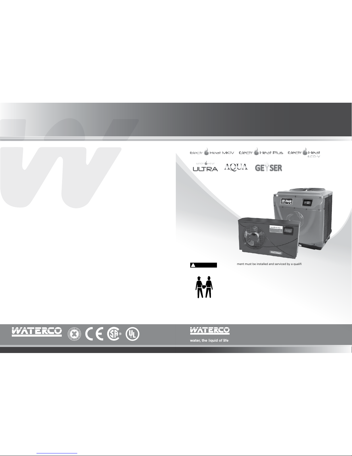
WATERCO POOL HEAT PUMP
L’eau, le liquide de la vie
Installation and
Operation Manual
Manuel d’installation
et d’utilisation
This equipment must be installed and serviced by a qualified technician.
Improper installation can create electrical hazards which could result in property
damage, serious injury or death. Improper installation will void the warranty.
Cet équipement doit être installé st réparé par un technicien qualiflié.
Une mauvaise installation peut entraîner des risques électriques qui pourraient
provoquer des dommages, des blessures graves ou la mort. Une installation
inadéquate annulera la garantie.
Notice to Installer / Avis à l’installateur
This manual contains important information about the installation, operation and
safe use of this product. Once the product has been installed this manual must
be given to the owner/operator of this equipment.
Ce manual contient des informations importantes sur l’installation, I’exploitation
et l’utilisation sécuritaire de ce produit. Une fois que le produit a été installé, ce
manuel doit être remis à l’acheteur et/ou utilisateur de cet équipement.
FLOW

I pg 02
Pool Heat Pump
Table of
IMPORTANT SAFETY INSTRUCTIONS
When using this electrical equipment, basic safety precautions should always be
followed, including the following:
READ AND FOLLOW ALL INSTRUCTIONS
! WARNING: Disconnect all AC power during installation and servicing.
! WARNING: In order to avoid the possibility of hyperthermia (heat stress) occurring
it is recommended the average temperature of the spa - pool water does not exceed
40˚C.
! WARNING: The pool heat pump is not intended for use by persons (including
children) with reduced physical sensory or mental capabilities, or lack of experience
and knowledge, unless they have been provided supervision or instruction concerning
use of the appliance by a person responsible for their safety. Children should be
supervised to ensure they do not play with the appliance.
• In certain situations unexpected start up may occur when the appliance is in
automatic mode.
• The installer should assess the risk associated with unexpected start-up of this
device which, in any circumstance should have no hazardous effect.
• The pool heat pump is not meant to provide safety protection for other devices.
• The pool heat pump should be deactivated if the pool or spa has been drained.
• Waterco pool heat pumps must be installed by a suitably qualified person in
accordance with current Regulatory Standards, the applicable Wiring Rules
(AS3000) and local statutory authority regulations.
• Parts containing live parts, except parts supplied with safety extra-low voltage
not exceeding 12V, must be inaccessible to a person in the spa – pool.
• Parts incorporating electrical components, except remote control devices, must
be located or fixed so that they cannot fall into the spa – pool.
• The appliance should be supplied through a residual current device (RCD) having
a rated residual operating current not exceeding 30mA.
• An Earth terminal is located inside the wiring enclosure. To reduce the risk of
electric shock, this terminal must be connected to the grounding means provided
in the electric supply service panel with a continuous copper wire as sized to
comply with current Standards and local statutory authorities in relation to the
circuit conductors supplying the equipment.
• A cable connector is provided on this unit to connect a suitably sized copper
conductor between this unit and any metal equipment, metal enclosures of
electrical equipment, metal water pipe, or conduit within 1.5m of the unit via
equipotential bonding.
SAVE THESE INSTRUCTIONS.
IMPORTANT SAFETY INSTRUCTIONS
------------
02
A NOTE TO YOU
--------------------------------------
03
INSTALLATION INSTRUCTIONS
--------------------
05
Location
------------------------------------------
05
Installation Clearances
--------------------------
06
Water Piping
-------------------------------------
07
Water Flow Rate
---------------------------------
08
Water By-pass Kit
-------------------------------
08
Plumbing Diagram
------------------------------
08
Electrical
------------------------------------------
09
Electrical Connection
---------------------------
09
Breaker Size -------------------------------------- 09
Electrical Wire Size
------------------------------
09
Bonding
-------------------------------------------
10
Bonding Diagram
--------------------------------
10
Remote Control Connections
------------------
11
Usage Of Chemical Products
------------------
12
OPERATION OF YOUR POOL HEAT PUMP
--------
13
CONTROLLER TYPES
Initial Heating
------------------------------------
13
Adjustment Of The Bypass Valves
------------
13
Pool Heat Pump Running Time
----------------
14
Pool Solar Blanket
-------------------------------
14
Defrost Cycle
-------------------------------------
14
To Start The Pool Heat Pump ------------------ 15
To Stop The Pool Heat Pump ------------------ 15
To Check and Adjust Temperature
Settings ------------------------------------------- 16
Temperature Calibration
------------------------
17
To Change Display From Farenheit To
Celcius
--------------------------------------------
18
Defrost for Electroheat Ultra
-------------------
18
Protection Devices
------------------------------
18
Codes
---------------------------------------------
18
INVERTER POOL HEAT PUMP CONTROLLER
----
19
Inverter Controller Operation
------------------------
20
Timer Function
-----------------------------------
20
Function Descriptions
--------------------------
21
Buzzer --------------------------------------------- 21
Memory Function
--------------------------------
21
MAINTENANCE OF YOUR POOL HEAT PUMP
----
22
Cabinet Cleaning
--------------------------------------
22
Cleaning Evaporator
----------------------------------
22
Cleaning drainage holes
------------------------------
22
Units Located In Coastal Locations
-----------------
22
Winterising Procedure
--------------------------------
23
GENERAL SAFETY INSTRUCTIONS
----------------
24
TROUBLESHOOTING
---------------------------------
25
Nothing Is Working and The
Electronic Control Does Not Operate
--------
25
Nothing Is Working But The Electronic
Control Temperature Displays Digits
or a Code
---------------------------------------
25
Fan Doesn’t Work (The Fan Blades
Are Not Moving)
--------------------------------
25
Fan Blades Turn, But Compressor Is Not
Functioning
----------------------------------------
26
Compressor Starts and Stops
-----------------
26
There Is Water Around The Pool Heat
Pump ------------------------------------------------
26
Pool Heat Pump Has Ice Formed On The
Evaporator Coil
---------------------------------
27
Pool Heat Pump Is Functioning, But Does
Not Reach The Desired Temperature
Setting -------------------------------------------- 27
Analysis Chart
------------------------------------
28
Circuit Breaker Trips
-----------------------------
28
The Pool Heat Pump Is Noisy
------------------
29
The Temperature Shown On Pool Heat
Pump Is Not The Same That Is
Shown By The Pool Thermometer
-------------
29
Service Analyser Codes
-------------------------
30
WARRANTY -------------------------------------------- 35

I pg 04
Pool Heat Pump
A NOTE TO YOU
Congratulations!
Thank you for choosing a Waterco pool heat pump to heat your pool.
Using the latest technology in heat capture, the Waterco pool heat pump converts
the energy released by the sun and transfers it efficiently to your swimming pool.
During certain periods it may be necessary to operate your pool heat pump
continuously during the day in cooler periods however, this should not be of concern
as your Waterco pool heat pump can heat up your pool 80% more economically than
the fossil fuel heating or heaters with electric elements.Waterco pool heat pumps are
designed specifically to heat up your swimming pool economically.
To appreciate the benefits that the product will bring you, make sure to operate
the unit when the atmospheric conditions specified in this document are present in
addition of using a solar blanket to minimize heat loss which will influence operating
costs and size of the unit required. Pools not covered with a solar blanket lose 2 to 3
times more heat, regardless of types of heating!
Record your model’s information.
Keep this manual and your original proof of purchase receipt for warranty and
future
reference.
On the base of your pool heat pump is a name plate which contains information
such as model number, serial number and electrical information.
Please write these down below and have them handy incase of a service call request.
Model Number _______________________________________________________________
Serial Number _______________________________________________________________
Purchase Date _______________________________________________________________
Dealer Name _______________________________________________________________
Dealer Address _______________________________________________________________
Dealer Phone _______________________________________________________________
To find detailed product information, the location of the nearest dealer or to
register your pool heat pump please visit our website www.waterco.com and
select your location.
I pg 06
Pool Heat Pump
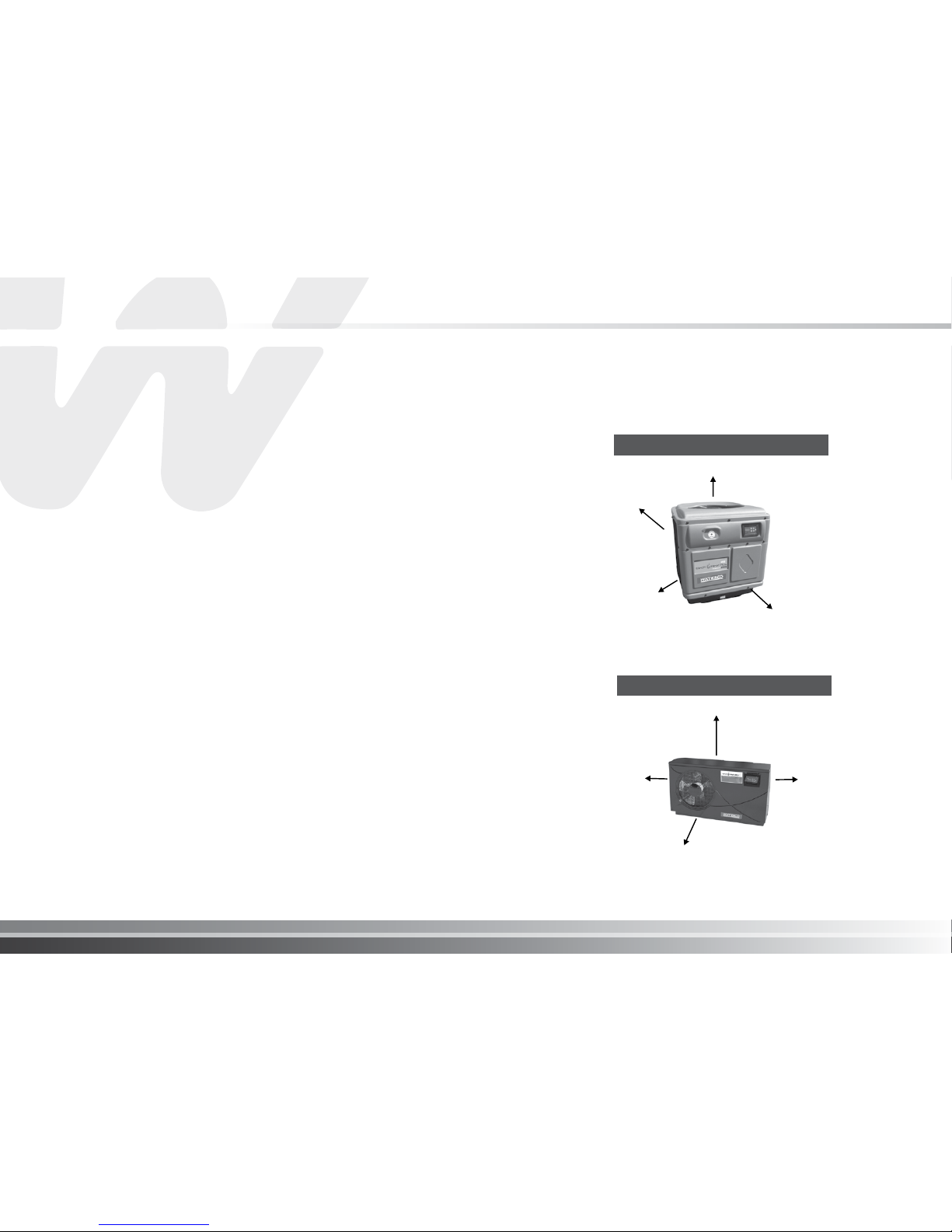
Installation Clearances
Air is pulled through the evaporator coil and discharged through the top or front
grill. Clearances must be allowed in front and around the unit for unrestricted
air discharge and service access. See Figure 1 and Figure 2. Failure to comply
to the set clearances may cause diminished unit performance and reduced unit
longevity.
INSTALLATION INSTRUCTIONS
Location
To gain maximum efficiency for your pool heat pump please follow all instructions
when “positioning the unit”. It is also important to allow clearances for future
service and maintenance procedures.
The unit is designed for outdoor installation and should not be installed in a totally
enclosed area such as a shed, garage, etc., unless assisted ventilation of the cold
exhaust air is provided to ensure adequate air exchange for correct operation. Recirculation of cold discharged air back into the evaporator coil should be avoided
and will greatly reduce unit’s heating capacity and efficiency.
The unit should be located as close as practically possible to the existing pool
pump and filter to minimize water piping. The use of 90 degree bends and short
radius elbows in the water piping should be kept to a minimum.
Mount the unit on a sturdy base, preferably a concrete slab or blocks. The base
should be completely isolated from the building foundation or wall to prevent the
possibility of sound or vibration transmission into the building. The size of the
base should not be less than the base of the pool heat pump.
Use of anti vibration mat between the base of the unit and final installation location
material is highly recommended to reduce potential vibration noise issues.
No obstruction above to allow cold air dispersal
clearance to rear
minimum 30cm
Clearance to side
minimum 60cm
Clearance to side
minimum 60cm
Top Discharge Models
Figure 1
Clearance to rear minimum 30cm
Side Discharge Models
Figure 2
No obstruction in front to
allow cold air dispersal
clearance to side
minimum 60cm
clearance to side
minimum 60cm
clearance to top
minimum 60cm
I pg 08
Pool Heat Pump
Water Flow Rate
The recommended water flow rate to ensure maximum heat transfer efficiency is between
120 - 300 litres per minute. The optimal flow rate is the mid point of this range. Use the
bypass valve to adjust the flow rate to within the recommended range.
Water By-pass Kit
A bypass kit consisting of three X two way valves must be installed for adjustment of water
flow and ease of service. Waterco offer prefabricated water bypass kits to fit their heat pump
domestic range. Ask your local Waterco sales office for details.
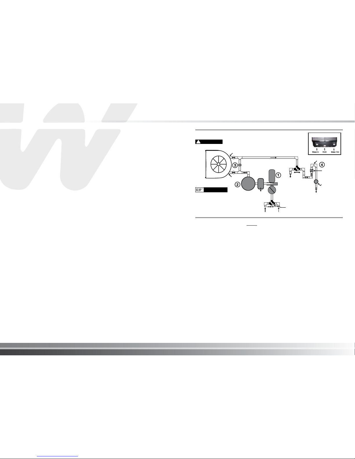
1. A check valve or a loop MUST be installed between the pool heat pump and
any automatic chlorinator to prevent highly chlorine concentrated water from
flowing back to the pool heat pump when the pool pump is not running.
2. Units which are located below the water level of the swimming pool may require
the pressure switch to be adjusted.
This can be checked by the following method:
i) switch on the water pump and pool heat pump.
ii) while the pool heat pump is running switch “OFF” the water pump.
If the pool heat pump shuts down automatically no further action is
required.
3. Units which are installed more than 1 metre below water level will require a
flocheck valve to be fitted to prevent the heat pump from cycling when no water
flow is detected.
4. For units installed above the pool water level the return water to the pool valve
on the bypass valve set should be closed approximately 15 - 20% to ensure the
heat exchanger is completely full of water to allow the heat transfer to occur.
!
VITAL
Plumbing connections to
the heater must be made
by hand only as it may
break the water Inlet or
Outlet connections.
IMPORTANT
Plumbing Diagram
Hookup
HEAT PUMP
Water Out
Water By-pass
PUMP
Filter
Water In
From Spa
From Pool
3 Way Valve
To Spa
SPA POOL
SPA POOL
Vertical Trap
Check
Valve
Chlorinator
or Chlorine
Generator
To Pool
MultiCyclone
Water Piping
The below plumbing layout must be followed without exception:
1. pool pump
2. filter
3. pool heat pump
4. chlorinator (when installed).
Rigid PVC piping is recommended with all joints primed and glued with a suitable PVC
adhesive cement. If rigid PVC pipe is not available,a suitable flexible hose of adequate
diameter may be utilised with stainless steel clamps. When the piping installation is complete,
operate the pool pump and check the system for leaks. Then check the filter pressure gauge
to see that excessive pump head pressure is not indicated.
IMPORTANT
Electrical
All electrical work should be performed by a fully qualified and licensed
electrician in accordance with local electrical codes.
An adequate circuit breaker and copper wiring must be used. Electrical
requirements are available on the name plate of the pool heat pump. It may be
necessary to install an earth leakage circuit breaker.
THE POOL HEAT PUMP MUST BE DISCONNECTED BEFORE
OPENING THE ACCESS PANEL.
WARNING
!
Electrical Connection
Standard 60 Hz power supply : 208/240 v - 60Hz-1 phase
Standard 50 Hz power supply : 208/240 v - 50Hz-1 phase
3 phase power supply : 200/230 v - 50/60 Hz - 3 phase
380/420 v - 50/60 Hz - 3 phase
Breaker Size
Please consult name plate on the base or the side of your pool heat pump for
starting amperage and required breaker size.
Electrical Wire Size
Please consult a qualified and licensed electrician.
The power cable ground must be connected to the electrical panel and to the
ground lug of the pool heat pump. An improper installation may be a potential
cause of fire, electrical shock or injury.
WARNING
!
I pg 10
Pool Heat Pump
Bonding
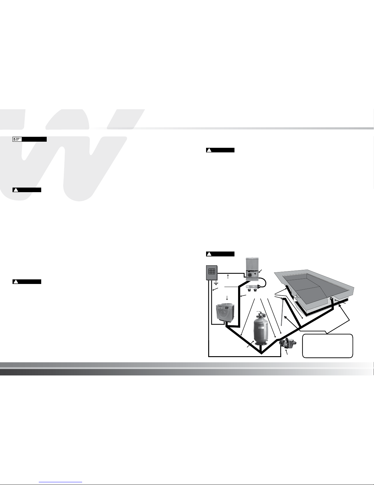
Because all metals have different electrical potentials, ALL metal and electrical components of
the pool system MUST be bonded together. This includes the metal framework of the pool, the
light, the pump, the filter (if metal), the pool heat pump, any automatic chlorine generator, and any
other metal or electrical equipment bonded to your pool.
On some older pools, this substructure bond wire may not exist. In these cases, a 3 - 4 foot solid
copper rod must be driven into the ground near equipment; all electric and metal components
must be bonded to each other, and to the copper rod. Warranty will be voided if system is not
properly bonded.
CAUTION: Some of these systems may leak stray voltage and currents into the water causing
severe electrolysis. This dramatically shortens the life of the pool heat pump and will void the
warranty.
When an automatic chlorinator is installed on a pool circulation system, it is important the
equipment is correctly installed and bonded (earthed). Some systems may leak stray voltage
and currents into the water causing severe electrolysis which could shorten the life of the pool
heat pump.
NOTE: Bonding to pool pump is not required to above ground pool pumps but all other
equipment must be bonded.
!
VITAL
Bonding Diagram
Pool House
Breaker Box
Power Supply
and Grounding
Wires Conduits
Chlorine
Generator
Heat Pump
Need bonding
if it is a metal filter
Pool Pump
If Pool Bonding Wire does
not exist, then a 3’ to
4’ Copper Rod must be
driven into the ground and
equipment bonded to it.
Light
3’ to 4’ Copper Rod
Bonding Wires
Pool Bonding Wire
!
VITAL
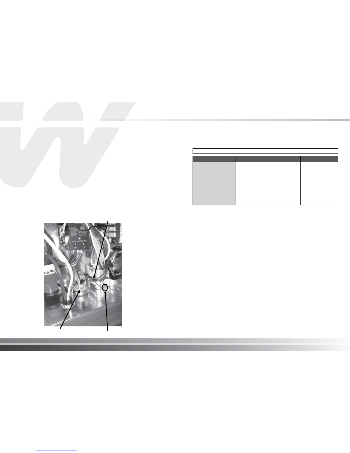
Remote Control Connections
1. Switch off power to heat pump at main circuit breaker panel.
2. Unbolt and remove the front access panel.
3. Open control box cover.
4. To connect a 2-Wire Control such as Waterco Aquamaster™, flocheck valve or timer:
ii) Locate the pressure switch either mounted on the bottom plate of the electrical
enclosure or the heat exchanger.
ii) Cut one of the cables connected to the pressure switch. Connect the two wires
from the Controller Normally Open Contact or flocheck valve to the two ends
of the cut cable and make electrically safe. Controller, timer or relay should be
sized to handle 24VAC at 0.5 Amp (because it will be completing the 24VAC
control board circuit on the heater as shown in Figure 24). Use 1mm2 minimum
cable with a minimum 1.2 mm thick insulation rated for a temperature rise of at
least 105°C.
5. Close control box cover.
6. Re-install the access panel. To control heaters that are operated in parallel, connect
wiring at same locations on heater Control. It is imperative that each control circuit is
isolated from the other control circuits; to avoid that current will flow from one heater to
another through the control circuits.
Pressure Switch 2 core cable from controller
cut one wire
* Warranty can be voided if not maintained within these ranges.
Usage Of Chemical Products
Never add liquid chlorine, granular chlorine, or slow dissolving tablets/ pucks into
the skimmer basket. This high concentration of chemicals should be avoided.
Water quality standards that must be strictly adhered to*:
I pg 12
Pool Heat Pump
DESCRIPTION NORMAL RANGE* VERIFY
PH Level 7.4 to 7.8 1 per week
Chlorine Concentration
1.0 to 4.0 PPM 1 per 2-3 days
Total Alkalinity
100 to 120 PPM 1 per 2-3 weeks
Total Dissolved Solids
Below 1800 PPM Reg. Pool 1 per month
Below 3500 PPM Salt. Pool 1 per month
Calcium Hardness
200 to 300 PPM 1 per month
I pg 14
Pool Heat Pump
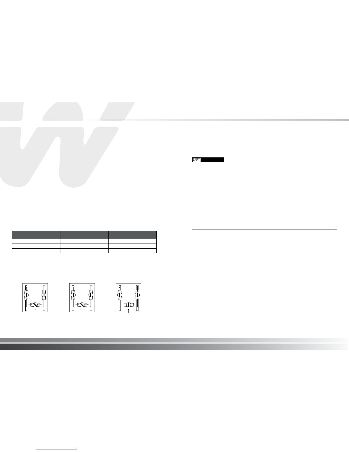
When the pool water
temperature is
between 65°F (18°C) and
70°F (21°C) please adjust
the bypass valve as shown.
Approx. 60% of the water is
circulating in the unit.
OPEN
VALVE POSITION
HEAT
PUMP
INLET
OULET
OPEN
VALVE POSITION
HEAT
PUMP
INLET
OULET
When the pool water
temperature is between
70°F (21°C) and 78°F (26°C)
please adjust the bypass
valve as shown. Approx. 80%
of the water is circulating in
the unit.
VALVE POSITION
CLOSED
HEAT
PUMP
INLET
OULET
When the pool water
temperature is above
79°F (26°C) please close the
bypass valve
as shown. 100% of the water
is circulating in the unit.
Model
Atmospheric conditions
must be above
Pool water temperature
must be above
Electroheat Ultra
32°F (0°C) 50°F (10°C)
Reversible (XLR) and Inverter
43°F (6°C) 65°F (18°C)
All others
52°F (11°C) 65°F (18°C)
Initial Heating
To achieve initial heating, your pool heat pump and the pool pump may require extended operation
until desired temperature is achieved. The initial heating time may vary depending upon the five
factors listed below. After initial heating, operating time may be reduced to match daily heat loss.
1. Size of the pool.
2. How many degrees the water is to be heated.
3. Ambient air temperature - the warmer the air, the less time required to heat.
4. Use of a solar blanket .
5. The size of the pool heat pump.
Atmospheric conditions as well as the pool water temperature should not be below the minimum
operating temperatures as stated below in order to obtain efficiency and avoid codes from
appearing on the electronic control temperature display; these codes are not generally a problem
with the pool heat pump at these conditions and is not covered by the warranty.
If a combination of the atmospheric and water temperatures are below the minimum listed
concurrently the pool heat pump should not be operated and be switched off.
Generally, atmospheric conditions (air temperature) will be warmer during day time hours. To
accelerate the initial heating period owners may opt to increase the ambient air temperature
artificially around the evaporator area of the pool heat pump until the pool water temperature has
reached the minimum required as stated below.
For Electroheat Ultra, Inverter and Reversible (XLR) units, they will automatically stop without
human intervention.
Adjustment Of The Bypass Valves
The adjustment may vary according to pool pump size and ambient temperatures.
ATTENTION: IT IS VERY IMPORTANT THAT THE BYPASS VALVES ARE SET AS DESCRIBED BELOW
FOR THE CORRECT FUNCTION OF YOUR POOL HEAT PUMP
Pool Solar Blanket
A pool solar blanket should be used whenever possible. Blankets minimize heat loss
through evaporation and conserve heat in your pool. Un-blanketed pool can lose
2-3 times more heat than a blanketed pool.
Defrost Cycle
When any of the following conditions occur the electronic control of your unit will
activate a defrost mode until all frost from the evaporator has melted. Condensation
of water on the evaporator coil tends to frost up quicker when the following occur.
1. When atomospheric conditions are as stated above;
2. When the evaporator is dirty;
3. When installation clearances are not respected.
Defrost is activated for between 3 to 20 minutes.
Pool Heat Pump Running Time
Most units should be sized to operate during the pool filtering cycle time of 8-12
daytime hours daily during warmer months and up to 8 hours daily during the
daytime in winter months. On warmer days the pool heat pump will run less
because the heat loss will be less.
Condensation
Your pool heat pump will accumulate condensed water (approx. 1 to 1.5 gallons or 4
to 6 litres per hour), therefore causing water to drain out of the unit base. In order to
avoid water accumulation, you may use decorative rocks around the concrete slab or
a basin under the unit. (Please note this is a normal characteristic of a pool heat pump
and not a service or warranty issue.)
IMPORTANT
OPERATION OF YOUR POOL HEAT PUMP
I pg 16
Pool Heat Pump
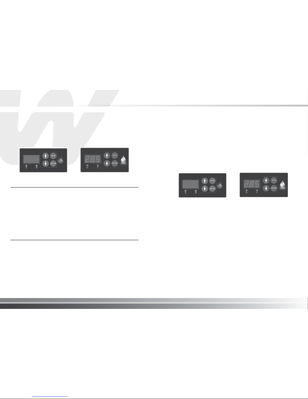
CONTROLLER TYPES
Electronic Control with Diagnostics for Standard
Models and Electronic Control with Diagnostics for
Reversible de-icing Models
Electronic Control
with diagnostics
Reversible (XLR) electronic control
with diagnostics
To Start The Pool Heat Pump
Press the button on the electronic control ON/OFF to start the pool heat pump.
The temperature display will show the pool water temperature flowing in your
pool heat pump and the fan motor starts (fan blade turns) but the compressor
does not start.
The temperature display flashes until the compressor starts and when the timer
will complete its cycle of 3 to 5 minutes. After 5 minutes, the compressor starts
and the temperature on the display stops flashing.
You can now program the desired temperature for the pool water.
To Stop The Pool Heat Pump
The pool heat pump can be stopped by pressing the ON/OFF button once.
To Check and Adjust Temperature Settings
To program the desired water temperature, press BOTH the UP and DOWN arrow keys at
the same time until the temperature degree displays change degree, then release them.
Press the UP arrow or DOWN arrow to program the desired temperature. The temperature
setting will automatically flash and will be saved. The display temperature will be revert
back to the pool water temperature when all keys have remained untouched for 5
seconds.
To change the temperature display from Fahrneheit (˚F) to Celcius (˚C). Press, the
button ˚C/˚F. The led below the ˚F or ˚C will be lit to indicate the current selection.
Note: The pool heat pump will cut out at once when the programmed temperature has
been reached.
Electronic Control
with diagnostics
Reversible (XLR) electronic control
with diagnostics
In addition to controlling the temperature of the water, this electronic control
informs you on the operation of your pool heat pump or any faults that may arise
by displaying codes on the temperature display.
When the unit is in defrost mode the code “DEF” is dispalyed on the temperature
display. This under normal conditions is not considered to be a fault.

I pg 18
Pool Heat Pump
Temperature Calibration
It is possible to have a temperature variation between the water in the swimming
pool and the reading of the pool heat pump temperature probe (sensor).
Example:if the water in the pool is 26º C (80º F) and the heat pump electronic
control displays 24ºC (76º F).
To calibrate this variation, perform the following procedure:
1. With the use of an accurate thermometer read the pool water temperature (e.g:
26˚C).
2. Read the temperature displayed on the pool heat pump electronic control (eg:
24˚C).
3. To determine the differential subtract the pool water temperature from the pool
heat pump displayed temperature, 26 - 24 = 2˚C. Therefore we must compensate
for the 2˚C variation.
4. Press BOTH the UP and DOWN arrow keys until the programmed temperature
is displayed (the temperature you have previously set) then release both
buttons.
5. Press the ON/OFF button and release.
6. Using the UP and DOWN arrows, enter the calibration value, (2˚C). In this case,
by pressing the UP arrow twice.
7. After 5 seconds when all the buttons have remained untouched , the display
temperature will show the pool water temperature as per your thermometer. If
this is the case the calibration process was successful.
To Change Display From Farenheit To Celcius
1. Press and release the SET key until F-C appears on the temperature display.
2. Whilst F-C is still on the display Press and release the UP or DOWN arrow key until C is
displayed.
3. Release all keys and the control will now be set for Celcius. (do not press any other keys
for 5 seconds)
To go back to Farenheit follow the same instructions above, however when you are at step 2,
F will need to be shown on the display before releasing all keys.
Defrost for Electroheat Ultra
During the defrost cycle, the fan motor stops working and the hot gas is injected into the
evaporator to melt the frost. However, when the pool heat pump makes 5 consecutive
cycles (heating and defrost) in less than 15 minutes, the unit goes into protection mode to
avoid inefficient use of electricity. These frequent defrost cycle’s mean that the conditions
of ambient temperature and humidity do not allow to heat your pool water. The FS4 code
will be displayed on the electronic control. Refer to the section titled ¨ Service Analyser
Codes ¨ to validate what you should do.
Protection Devices
The integrity and performance of your pool heat pump and its components are protected
by internal safety controls. In normal use, your Waterco unit should never reach the thermal
protection level. However, if it should happen, you should identify the stated code on the
temparature display and refer to Service Analyser codes.
Codes
If a code appears on the electronic control refer to Service Analyser codes (all standard
models) on page 29.
Inverter Controller Operation
Button functions are as indicated below:
“
” button: Press briefly then release to switch the machine on/off, press 3
seconds to lock or unlock buttons.
“
” (Up), “ ” (Down) buttons: To set temperature, off timer, to increase or
decrease parameters.
“
” button: Press briefly then release for on and off timer functions, press 3
seconds to set clock.
“
” button: Press briefly then release to set low-auto when set to heat,
intermediate-frequency, high-frequency and auto when set to heat.
“
” button: Press 3 seconds to switch between cooling, heating and automatic
mode.
Timer Function
1. A 24hr timer function is included in the units controller which may be set in one
minute increments.
2. On timer function: - When the heat pump is switched off, enter the settings
menu and set the on timer to switch the unit on automatically.
3. Off timer function: - When the heat pump is switched on, enter the settings
menu and set the off timer to switch the unit off automatically.
4. The timer function may repeat and is only deactivated when the ON / OFF
button is selected.
5. Timer error is less than 1min/h.
Note: Timer time is calculated based on Clock time.
I pg 20
Pool Heat Pump
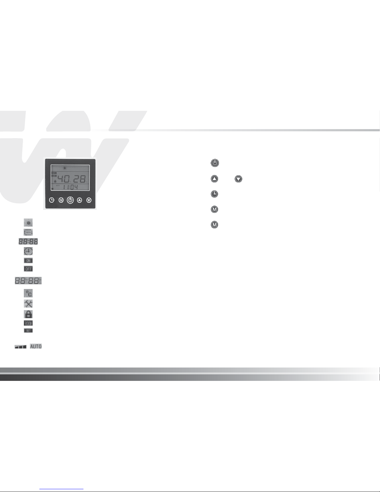
Inverter Pool Heat Pump Controller
This controller applies to DC inverter air source pool heat pumps, for heating.
Heating
Automatic Mode
Clock/ Timer/ Function Display
Clock Adjustment Icon
On Timer Icon
Off Timer Icon
Temperature Display - the numerals on the left side indicate the set
water temperature. The numerals on the right side of the display
indicate the pool water temperature.
Temperature Icon (in degree Celsius)
Function Settings Icon
Keypad button lock is active
Real-time Temperature Distinction Icon
Set Temperature Icon
,
When heating mode is selected the units operating speed is indicated
as follows - one bar - low speed, two bars - medium speed and three
bars - high speed. The unit also has an AUTO mode where the units
heating rate is automatically selected according to the air, set and pool
water temperatures.

MAINTENANCE OF YOUR POOL HEAT PUMP
Waterco pool heat pumps have been specifically engineered to give you years of
satisfaction and enjoyment in the pool.
Cabinet Cleaning
To clean the plastic surfaces use mild soapy water and a soft clean cloth. Never use
solvents or abrasives.
Cleaning Evaporator
The evaporator at the rear of the unit must be kept clean and un-obstructed in order for
your pool heat pump to have better efficiency and avoid problems which may void your
warranty. The dirt collected in the evaporator can be removed with a gentle water spray
and the use of a soft brush. Be careful not to damage the aluminum fins.
Cleaning drainage holes
The condensate drainage holes in the base of the unit must be kept free of debris. Blocked
drainage holes may cause water to collect in the unit and become stagnant or, interfere
with electrical components and wiring.
Issues caused by blocked drainage holes in the base of the unit are not covered under
warranty.
Units Located In Coastal Locations
Care and maintenance procedures for Waterco Pool Heat Pumps installed in coastal
locations.
Exposure to salt may result in evaporator coil damage shortening the life of the equipment.
Bare aluminium fins can deteriorate rapidly depending on a number of factors including
fin design, location of the equipment relative to salt water, and maintenance.
For Waterco pool heat pumps located within one kilometre from the coast a coating must
be applied to the unit prior to site delivery on the evaporator fins and exposed metal
surfaces to reduce the incidence of corrosion.
A monthly rinse with potable water straight from the garden hose connected to the
municipal water system to remove the salt build up on the evaporator coil and exposed
metal surfaces is necessary.
I pg 22
Pool Heat Pump
Function Descriptions
1. When power to the unit is switched on the controller display will illuminate.
2. Use the UP and DOWN arrow buttons on the keypad to adjust. Adjustable
functions: For users, the current temperature, flash, “ ” and “ ” to adjust, press
ON/OFF button to return to the current status. To fully adjust cooling, heating,
automatic temperature, users need to enter cooling, heating and automatic
mode respectively for adjustment.
3. In auto mode, the units operating speed is displayed on screen.
4. Backlight will be illuminated when buttons are pressed. Backlight will be turned
off if button is not pressed in 1 minute.
Buzzer
Under any operation, a buzzer will sound when any button on the keypad is pressed.
When the unit reports a fault the buzzer will be silent and the code will be displayed
on the controller screen.
Memory Function
The heat pump controller should memorise ON / OFF status, operating mode,
parameter and timer settings. When power is connected and the heat pump is
switched on, the unit will start operation based on the settings when power was
switched off previously.

GENERAL SAFETY INSTRUCTIONS
DO NOT DEPRIVE YOUR POOL HEAT PUMP OF WATER FLOW FOR MORE
THAN 24 HOURS WITHOUT DRAINING IT. Make sure you leave the bypass
valves as shown in Figure 1.
At the end of each season, when the pool heat pump is no longer in use, and
proper pool water chemistry is not maintained, it should be disconnected from the
water line and drained to prevent any possible corrosion or damage to the pool
heat pump. Refer to Figure 1 below or winterising procedure (page 24).
Pool heat pump Pool heat pump
OUT
IN
OUT
IN
When your valves position are as
shown on Figure 1, the water is
bypassing the pool heat pump.
Figure 1
When your valves position are as
shown on Figure 2, the water is
going through the pool heat pump.
Figure 2
The valves shown above may be different to the ones installed on your system.
Please ensure you understand how your bypass valve operates.
I pg 24
Pool Heat Pump
Winterising Procedure
If the pool heat pump is stored in a place where the temperature drops below
the freezing point of 0˚C (32°F); it is mandatory that the water accumulated in
the pool heat pump be drained completely before freezing weather prevails.
Improper winterizing may damage the pool heat pump and will void the warranty.
• Turn the pool heat pump “OFF”.
• Turn the pool heat pump breaker “OFF”.
• The water piping MUST be disconnected to drain the pool heat pump’s heat
exchanger in preparation for winter.
• Once the piping is disconnected, the pool heat pump’s heat exchanger MUST
be emptied; the use of a water vacuum cleaner is strongly recommended or if
you do not have this tool you may tilt the unit (75˚) until all the water is out.
• It is recommended that pool heat pump’s heat exchanger is rinsed out with a
gentle water spray at the inlet and outlet water connections of the pool heat
pump and then drain the heat exchanger again.
• With the help of 2 pool return winter plugs, block the water Inlet and Outlet
connections to prevent access by vermin.
• Clean the drainage holes located at the bottom of the base of the unit.
• Unit may be covered for the winter.
• It is also possible to fill the heat exchanger with pool anti-freeze, but ensure that
the antifreeze contains an elevated pH to prevent corrosion. This is optional
and requires appropriate hardware.
!
VITAL

Fan Blades Turn, But Compressor Is Not Functioning
The pool heat pump has a built in delay timer which prevents the compressor from starting
immediately. The delay can be 3 to 5 minutes in duration after the fan blades have turned.
Furthermore if the unit is in defrost mode the compressor will not start for 3 to 20 minutes.
1. Check that air being discharged from the fan blades is colder than the ambient air. If
the air being discharged by the fan blades is colder, it means that the compressor is
functioning correctly.
2. Turn off the pool heat pump then immediately turn it back on;
3. As soon as the fan blades start turning, wait a minimum of 3-5 minutes. The compressor
should start up after this time and you will be able to identify a different sound made by
the compressor when it starts;
4. If the compressor is functioning, but shuts off immediately, consult the following section
“ Compressor Starts and Stops “.
5. If the problem persists, call your local Waterco office for assistance.
Compressor Starts And Stops
1. Check that the unit has been installed correctly (refer to installation procedures).
2. Check that the water inlet and outlet of the unit have not been connected incorrectly.
There Is Water Around The Pool Heat Pump
It is a normal occurrence for water condensation, to be seen running from the unit base. There
will be on average 1 to 1.5 gallons (4 to 6 litres) of condensed water per hour being discharged
from the unit base. In order to avoid water accumulation, you may use decorative
rocks around the concrete slab or a basin under the unit. Be sure that clearances around the
unit are respected.
To test the unit and confirm you have no pool water leaking from the unit perform the
following test which is best performed early in the morning and continuing for the whole day:
1. Turn off the pool heat pump from the circuit breaker and the pool pump.
2. Open the bypass valve. (refer to drawing on page 5)
3. Close the IN and OUT water valves on the unit.
4. Restart the pool pump. The pool heat pump must remain OFF.
5. When all of the water around the base of the pool heat pump has dried, open the water
IN and water OUT valves on the pool heat pump.
6. Close the bypass valve to allow full water flow through the pool heat pump.
If water is now seen running from the outside of the pool heat pump or inside the pool heat
pump after a short period of time you should call for service. If no water is seen after a short
period of time it would be assumed the water was condensation which is normal.
I pg 26
Pool Heat Pump
TROUBLESHOOTING
Please ensure the unit and any related equipment is installed in accordance with the
installation manual. If not, the Waterco warranty will not apply and the customer may
be liable for service call charges.
Nothing Is Working And The Electronic Control
Does Not Operate
1. Ensure the circuit-breaker has not tripped and/or the fuses have not blown;
**Take note that only an electrician can verify if the circuit breaker is defective;
if this is the case, repairs will not be covered under the warranty.
2. For three phase models, this situation could occur when phases are not in the appropriate
order. The green led light on the front panel will not light up.
Please have a qualified electrician swap over two of the incoming phase wires.
Nothing Is Working But The Electronic Control
Temperature Displays Digits Or A Code
1. Identify the analyser code that the electronic control displays and refer to the
Service Analyser codes section;
2. If the electronic control displays digits, make sure that the electronic control
is programmed correctly, refer to the Operation of your pool heat pump and
reprogram if necessary.
**Note that this situation could occur when the electrical voltage is not respected
as stated on the pool heat pump name plate. This situation is not covered by the
manufacturer warranty.
Fan Doesn’t Work (the fan blades are not moving)
1. IMPORTANT: For safety, switch OFF the circuit-breaker.
2. Try to rotate the fan blades of the fan with a rod to see if the motor is jammed or seized
3. If the fan blades do not turn freely leave the unit switched OFF and call for service;
4. If the fan blades turn freely switch ON the circuit breaker and the pool heat pump again.
** Note that your fan motor may have an electrical fault if the blades turn freely when the
unit is switched OFF and does not start when the unit is switched ON.

Circuit Breaker Trips
If you have purchased a remote control (or other equipment), ensure the equipment
is correctly installed. If an operational issue originates from incorrect operation or
installation of this equipment, Waterco’s warranty will not apply and you will have to
pay the cost of the service call.
1. The amperage of the circuit breaker AND the electrical wiring must be as the
instructions on the pool heat pump name plate, otherwise notify your installer or
electrician to correct this problem, as this is not covered under the warranty.
2. If the circuit breaker and electrical wiring are as stated, make sure the drains,
located on each side of the base of the pool heat pump are not obstructed.
IMPORTANT
Analysis Chart
Important: Please record all information
for three consecutive days at 12h00
Day 1 Day 2 Day 3
Outside air temperature .................................................................
Weather conditions outside (eg: cloudy, sunny or rainy) ................
Pool water temperature ......................................**Use a pool
thermometer
Pool water temperature ..................................... **use the reading
from the electronic control on the pool heat pump
Important: Please record all information
for three consecutive days at 20h00
Day 1 Day 2 Day 3
Outside air temperature .................................................................
Weather conditions outside (eg: cloudy, sunny or rainy) ................
Pool water temperature ......................................**Use a pool
thermometer
Pool water temperature ..................................... **use the reading
from the electronic control on the pool heat pump
I pg 28
Pool Heat Pump
Pool Heat Pump Is Functioning, But Does Not
Reach The Desired Temperature Setting
Improper installation may cause this situation and will need to be corrected by the
owner.
1. Ensure the by-pass valves are in the correct positions to ensure sufficient water
flow, insufficient water flow will cause the compressor to shut off early.
2. If you have installed a timer or the pool heat pump is equipped with an integrated
timer, be sure it is programmed to allow the pool pump to work for sufficient time
in order to reach the programmed temperature.
3. Ensure the evaporator is cleaned regularly with a light spray of water and allowed
to dry before re-starting the pool heat pump to avoid premature ice build up on the
evaporator.
4. Waterco recommend the use of a solar cover to retain heat in pool water. Pools
without covers lose 2 to 3 times more heat than pools with solar covers.
5. Make sure the electronic control of your pool heat pump has been programmed
correctly;during this test the pool heat pump and water pump must be working
continuously (eg; the desired water temperature must be set correctly).
6. If the unit continually fails to reach the desired water temperature, we suggest
completing the following analysis chart and forwarding it to Waterco in order to
avoid unnecessary service fees.
IMPORTANT
Pool Heat Pump Has Ice Formed On The Evaporator
Coil
1. IMPORTANT: For safety, switch OFF the circuit-breaker.
2. Allow the ice to melt and then inspect the evaporator to ensure it is free of debris and
leaves.
3. If the evaporator is dusty or dirty, clean it with a light spray of water and allow it to dry
(do not use high pressure it may damage the evaporator fins).
4. When the unit is dry, you may switch it back ON from the circuit breaker.
5. Ensure that the clearances around the unit are respected.
6. When the unit has been switched ON ensure the fan motor is working (fan blades will
be turning) while the compressor is operating.
7. If the fan blade does not turn and the compressor is functioning; notify customer service.
**If the pool heat pump requires service, the owner of the pool heat pump will need to
ensure the unit has been switched OFF to allow any ice to melt prior to any technician
attending.

Code Problem - Action / Remedy
dPd, oC2,
Sc2
Problem: The air intake temperature defrost probe has a loose
connection or is faulty. The probe will need to be checked
(defrost probe), and replaced if required.
Action / Remedy: Contact customer service.
FLo, FL3
nFL
Problem: No water flow, not sufficient water flow through the pool
heat pump or the water pressure switch needs to be adjusted or is
defective.
Action / Remedy: If the pool pump is connected to the pool heat
pump make sure the electronic control that runs the pool pump
and pool heat pump are programmed correctly
If the code is still displayed:
- Make sure the pool pump is switched ON;
- Press ¨SET¨ or ¨ON/OFF¨ depending on the model, to restart the
pool heat pump;
- On new installations, ensure the installation instructions were
respected;
- Check that the pool water level is correct, that the pool pump is
filled with water to the rim and that water is flowing correctly
through the pool pump to the pool heat pump;
- Check swimming pool and pool pump skimmer baskets and the
drain at the bottom of the pool for obstructions;
- Check the filter cartridges for obstructions (wash or change the
cartridges);
- Carry out a backwash for sand filters and ensure they are working
correctly;
- Ensure that the bypass valves are in the correct positions so that
the water flows adequately;
- Ensure vacuum robot or other cleaners are disconnected so that
the water flows freely.
- Check that there are no leaks on the pool plumbing (there should
be no air leaks in the pipework);
Service Analyser Codes (Standard Models)
Most operating issues will be detected by the electronic control and a code will
appear on the temperature display. Ensure the Action / Remedy suggestions are
followed prior to booking a service call and avoid unnecessary call out fees. If
the code remains on the display after you have followed the Action / Remedy
instructions, please contact Waterco.
I pg 30
Pool Heat Pump
The Pool Heat Pump Is Noisy
1. Check the pool heat pump is level and on a solid base to prevent any vibrations
issues.
2. Ensure the noise is coming from the pool heat pump, not from other equipment
which will not be covered by the warranty (for example: noise coming from the
bypass valve, pool pump, etc);
3. An improper installation may cause this situation it will need to be corrected by the
owner.
The Temperature Shown On Pool Heat Pump
Is Not The Same That Is Shown By The Pool
Thermometer
It is possible to have a temperature variation between the temperature shown
on the electronic control temperature display of the pool heat pump and a pool
thermometer which may be read from different locations. Please refer to the
temperature calibration section in order to adequately recalibrate temperature if
required.
- Check that there are no leaks on the pool plumbing (there should be no air leaks in
the pipework);

Code Problem - Action / Remedy
LP, LP3 Problem:
Low refrigerant level in the pool heat pump or the low-
pressure safety control is defective.
Atmospheric conditions as well as the pool water temperature
should not be below the minimum operating temperatures as stated
below in order to obtain efficiency and avoid codes from appearing
on the electronic control temperature display ; these codes are not
generally a problem with the pool heat pump at these conditions
and is not covered by the warranty.
If temperatures are below the minimum temperatures listed below
the pool heat pump should not be operated and must be switched
off.
Model
Atmospheric
conditions
must be above
Pool water
temperature
must be above
Electroheat Ultra 32°F (0°C) 50°F (10°C)
Reversible (XLR) 43°F (6°C) 65°F (18°C)
All others 52°F (11°C) 65°F (18°C)
Action / Remedy:
- If the LP or LP3 code is shown permanently, press “SET” or “ON/
OFF” depending of the model you have before to get to next step;
- Ensure the evaporator is clean. If not switch the unit OFF from
the circuit breaker (fuse) and use a garden hose to lightly clean
the evaporator, then allow it to dry before re-starting the pool heat
pump to avoid premature ice build up on the evaporator.
- Ensure installation instructions have been followed. Improper
installation, e.g. no air circulation could lead to the pool heat pump
continually going into LP or LP3 mode and the installation will
need to be corrected by the owner.
HP, HP3 Problem:
Low water circulation in the unit or the high-pressure
control is defective. If the HP code is triggered and displayed
3 times; this will cause the pool heat pump to shut down
automatically. The HP3 code will then appear permanently
(except for reversible electronic control with diagnostics).
Note: The pool pump will stop functioning only if the internal
time delay of the pool heat pump is being used.
IMPORTANT: When the code HP3 is permanently displayed,
before performing the steps below, please press the ¨SET¨ button
for the electronic control Multi Function and ¨ON / OFF¨ for the
electronic control with diagnostics and the reversible electronic
control with diagnostics (XLR) and electronic control with
diagnostics.
I pg 32
Pool Heat Pump
Code
Problem - Action / Remedy
FS, DEF, FS4 Problem:
Normal defrost cycle. The fan blades are turning, but
the compressor has stopped. For Electroheat Ultra and Reversible
model, the fan blades do not turn but the compressor runs.
Action / Remedy:
Normal during defrost duration.
Atmospheric conditions as well as the pool water temperature
should not be below the minimum operating temperatures as
stated below in order to obtain efficiency and avoid codes from
appearing on the electronic control temperature display ; these
codes are not generally a problem with the pool heat pump at
these conditions and is not covered under warranty.
If temperatures are below the minimum temperatures the pool heat
pump should not be operated and must be switched off.
For Electroheat and Reversible (XLR) units, they will automatically
stop without human intervention.
Model
Atmospheric
conditions
must be above
Pool water
temperature
must be above
Electroheat Ultra 32°F (0°C) 50°F (10°C)
Reversible (XLR) 43°F (6°C) 65°F (18°C)
All others 52°F (11°C) 65°F (18°C)
For Electroheat model: If the unit carries out 5 consecutives defrost
cycles every 15 minutes or less, the pool heat pump is then put into
protection mode (FS4). During this mode, the fan blade turns for
30 minutes in order to cool the evaporator. The pool heat pump
restarts automatically when the external temperature is at: 34˚F
(1˚C).
For Reversible (XLR) Model: If the unit performs 4 consecutive
cycles (heating and defrost) within 1-hour, the unit goes into
protection mode and alternately displays the water temperature
and the DEF code. The fan motor runs for 30 minutes to cool the
evaporator and then stops. The compressor is always off. The unit
restarts automatically when the outside temperature is 43°F (6°C)
and more.
If the code stays on permanently:
- Ensure the evaporator is clean. If not
switch the unit OFF from
the circuit breaker
(fuse) and use a garden hose to lightly clean
the evaporator, then allow it to dry before re-starting the pool heat
pump to avoid premature ice build up on the evaporator.
- Ensure installation instructions have been followed, Improper
installation, e.g. no air circulation could lead to the pool heat pump
continually going into defrost mode and the installation will need to
be corrected by the owner.

I pg 34
Pool Heat Pump
Code Action
EE 01
High-pressure Failure
EE 02
Low-pressure Failure
EE 03
Water Flow Failure
EE 04
Heating Water Temperature Overheating Failure
EE 05
Exhaust Temperature Failure
EE 06
Wired Controller EEPROM Data Read/Write Failure
EE 07
Converter Board EEPROM Data Read/Write Failure
EE 08
Wired Controller and Converter Board Communication Failure
EE 09
Converter Board and Outdoor Board Communication Failure
EE 10
Outdoor Board and Module Board Communication Failure
EE 11
Module Board Failure
EE 12
DC Bus Overvoltage, Low-Voltage Protection
EE 13
Overcurrent Protection
EE 31
Outdoor DC Fan Failure (only for DC Fan Model)
PP 01
Inlet Water Temperature Sensor Failure
PP 02
Outlet Water Temperature Sensor Failure
PP 03
Outdoor Coil Sensor Failure
PP 04
Return Air Sensor Failure
PP 05
Outdoor Environment Sensor Failure
PP 06
Compressor Exhaust Sensor Failure
PP 07
Winter Antifreeze Protection
PP 08
Low Ambient Temperature Protection
PP 09
Heating Ambient Temperature Overheating Protection
PP 10
Cooling Outer Coil Overheating Protection
Defrosting
Defrosting Indicator Heating Icon Flash Prompt
Code Problem - Action / Remedy
HP, HP3 Action / Remedy:
Make sure the water reaches the pool heat
pump and the pool pump is completely filled to the rim. Otherwise:
- Fill the pool pump with water, and check to see if the pipes
between the pool pump and the pool are watertight (there should
be no air intake);
- Check the swimming pool and pool skimmer baskets and the drain
at the bottom of the pool for obstructions;
- Check the filter cartridges for obstructions (wash or change the
cartridges, as the case may be);
- Insure that the bypass valves are in the correct positions so that
the water flows adequately;
- Backwash sand filter (insure that there is a sufficient amount of
sand and verify that it does not have to be changed. Consult a
swimming pool specialist if necessary);
- Make sure the vacuum robot is disconnected so that the water
flows freely.
OFF Problem:
The desired water temperature setting programmed
is below 60°F (15°C) for the Multi function electronic control
OR the electronic control with diagnostics is OFF or could be
defective.
Action / Remedy:
Reprogram the desired water temperature
setting to a higher setting for the electronic control with Multi
Function. For the electronic control with diagnostics and the
reversible electronic control with diagnostics (XLR), press on key
¨ON/OFF¨.
PSD, oC1 &
Sc1
Problem:
The water temperature probe has a loose connection
or is faulty. The probe will need to be checked and replaced if
required.
Action / Remedy: Contact customer service.
ot
Problem:
Water temperature is higher than 45°C (113°F) within
the unit (this code is only displayed on the electronic control with
diagnostics).
Action / Remedy:
- Make sure the bypass valves are in the correct positions;
- Proceed to the calibration of the electronic control with diagnotics
and reversible electronic control with diagnostics (XLR).
Service Analyser Codes (Inverter Models)

WARRANTY
Waterco’s obligation to repair or replace at Waterco’s option, shall be the original
purchaser’s sole and exclusive remedy under this warranty. Waterco shall not be liable for
incidental, consequential or special damages arising out of or in connection with product
use or performance.
Waterco is not responsible for direct or indirect damages resulting from defective
components. This warranty gives you specific legal rights and you may also have other
rights, which vary from state, province or country to another.
Prior to contacting Waterco for assistance or service, please check the
“Troubleshooting” and the information stated in this section. Warranty will only cover
manufacturing defects. All service call requests which are not of this nature must be
paid by the purchaser to the service company authorized by Waterco.
All services will be handled by the authorized service company. Warranty may be
voided if service is not carried out by a Waterco authorised service agent.
DO NOT
return the pool heat pump to your dealer as they do not provide the service
work.
Prior to contacting Waterco for assistance Waterco for assistance or service, in order to
qualify for a warranty claim, the original purchaser must have the model name and serial
number along with a proof of the original purchase date. Proof of purchase must be
forwarded to Waterco and they will inform you of the applicable warranty.
Once connected with a Waterco customer service agent, proceed to describe in detail
the issue associated with your pool heat pump. If a permanent code appears on the
electronic control panel, please advise the Waterco service agent.
There are no other warranties, express or implied, including, but not limited to, implied
warranties of merchantability or fitness for a particular purpose. During warranty period,
Waterco will, at its option, repair or replace, without charge, any product or part, which
is found to be defective under normal use and service.
IMPORTANT :
The warranty is not transferable and no action can be exercised by a
consumer subsequent purchaser of the pool heat pump.
IMPORTANT
Waterco does not guarantee and will not pay for:
A. Service calls to:
1. Inspect and/or correct the installation of your pool heat pump.
2. Instruct you on how to use your pool heat pump.
3. Replace house fuses or correct power supply problem.
4. Adjust or reestablish water flow to the pool heat pump.
B. When a service call with no manufacturing problem has been detected, on site, by
the service company mandated by Waterco.
C. Damage to your pool heat pump caused by accident, misuse, fire, flood, acts of
God, improper installation, harsh environment, chemical feeding before the pool
heat pump, improper maintenance of water chemistry or any problem related with
installation instructions not followed and described in this manual by the purchaser
and/or the end-user.
D. Damage to internal piping or components due to improper winterizing before
freezing conditions.
E. Repairs to parts or system resulting from unauthorized modification made to the
pool heat pump.
F. Repairs not previously authorized by Waterco.
G. Parts and pool heat pump transportation.
H. Fees charged for excessive time to repair your pool heat pump due to incorrect or
un-accessible location This may void warranty cover and the owner will be required
to pay a service call fee even if the unit is not repaired.
I pg 36
Pool Heat Pump

I pg 02
Thermopompe
Table des
INSTRUCTIONS DE SÉCURITÉ IMPORTANTES
Lors de l’utilisation de cet équipement électrique, des précautions de sécurité de
base doivent toujours être suivies, notamment :
Lisez et suivez les instructions
! AVERTISSEMENT : Débranchez de toute alimentation en courant alternatif (AC)
pendant l’installation et l’entretien !
! AVERTISSEMENT : Afin d’éviter toute possibilité d’hyperthermie (stress thermique),
il est recommandé que la température moyenne de l’eau de la piscine ne dépasse
pas 40 ° C. !
! MISE EN GARDE : La Thermopompe de la piscine n’est pas destinée aux personnes
ayant des capacités sensorielles physiques ou mentales réduites (y compris les
enfants), ou manquant d’expérience et de connaissances, à moins de recevoir
une supervision ou des instructions concernant l’utilisation de l’appareil pour leur
sécurité. Les enfants doivent être surveillés pour s’assurer qu’ils ne jouent pas avec
l’appareil.
• Dans certaines situations, un démarrage inattendu peut se produire lorsque
l’appareil est en mode automatique.
• L’installateur devrait évaluer le risque associé au démarrage intempestif de ce
dispositif qui, en toute circonstance ne devrait avoir aucun effet dangereux.
• La Thermopompe n’est pas supposée fournir une protection de sécurité pour
d’autres appareils.
• La Thermopompe doit être désactivée si la piscine ou le Spa a été vidangé.
• Les thermopompes Waterco pour le chauffage de piscine doivent être installées
par une personne qualifiée ; conformément aux normes réglementaires, aux règles
de câblage applicables (AS3000) et aux réglementations locales en vigueur.
• Les pièces comportant des composants électriques, à l’exception des dispositifs
de commande à distance, doivent être situées ou fixées de manière à ne pas
pouvoir tomber dans la piscine.
• L’appareil doit être alimenté par un dispositif à courant résiduel (RCD) ayant un
courant de fonctionnement résiduel nominal ne dépassant pas 30 mA.
• Une borne de terre est située à l’intérieur de l’enceinte de câblage. Pour réduire
le risque d’électrocution, cette borne doit être connectée aux moyens de mise
à la terre fournis dans le panneau d’alimentation électrique avec un fil de cuivre
continu conforme aux normes en vigueur et aux prescriptions locales en vigueur
en ce qui concerne les conducteurs de circuit.
• Un connecteur de câble est fourni sur cet appareil pour connecter un conducteur
en cuivre de taille appropriée entre cet appareil et tout équipement métallique,
boîtiers métalliques d’équipement électrique, tuyau d’eau métallique ou tout
conduit à 1,5 m de l’appareil par liaison équipotentielle.
VEUILLEZ CONSERVER CES INSTRUCTIONS.
IMPOINSTRUCTIONS DE SÉCURITÉ IMPORTANTES
------------
02
Une note à vous
---------------------------------------
03
INSTRUCTIONS D’INSTALLATION
-----------------
05
Emplacement
------------------------------------
05
Dégagements d’installation
--------------------
06
Tuyauterie d’eau
---------------------------------
07
Débit d’eau
---------------------------------------
08
Kit de dérivation d’eau
-------------------------
08
Diagramme de plomberie
----------------------
08
Électrique
-----------------------------------------
09
Connexion électrique
---------------------------
09
Taille du disjoncteur ----------------------------- 09
Taille du fil électrique
----------------------------
09
Collage
--------------------------------------------
10
Diagramme de collage
--------------------------
10
Connexions de contrôle à distance
-----------
11
Utilisation de produits chimiques
-------------
12
FONCTIONNEMENT DE LA POMPE À CHALEUR DE
VOTRE PISCINE
-----------------------------------------
13
TYPES DE CONTRÔLEUR
Chauffage initial
---------------------------------
13
Ajustement des vannes de dérivation
--------
13
Temps de fonctionnement de la pompe à
chaleur de piscine
-------------------------------
14
Couverture solaire de piscine
------------------
14
Cycle de dégivrage
------------------------------
14
Pour démarrer la pompe à chaleur de
piscine -------------------------------------------- 15
Pour arrêter la pompe à chaleur de
piscine -------------------------------------------- 15
Pour vérifier et ajuster Paramètres de
temperature -------------------------------------- 16
Étalonnage de la température
-----------------
17
Pour changer l’affichage de Farenheit
à Celcius
------------------------------------------
18
Dégivrage pour Electroheat Ultra
-------------
18
Dispositifs de protection
-----------------------
18
Codes
---------------------------------------------
18
CONTRÔLEUR DE POMPE À CHALEUR
D’INVERTER POOL
------------------------------------
19
Fonctionnement du contrôleur de l’onduleur
-----
20
Fonction de minuterie
--------------------------
20
Descriptions des fonctions
---------------------
21
Buzzer --------------------------------------------- 21
Fonction de mémoire
---------------------------
21
ENTRETIEN DE VOTRE POMPE À CHALEUR
POOL
------------------------------------------------------------
22
Nettoyage de l’armoire
-------------------------------
22
Nettoyage de l’évaporateur
--------------------------
22
Nettoyage des trous de drainage
-------------------
22
Unités situées dans des endroits côtiers
-----------
22
Procédure d’hivernage
--------------------------------
23
INSTRUCTIONS GÉNÉRALES DE SÉCURITÉ
------
24
DÉPANNAGE
-------------------------------------------
25
Rien ne fonctionne et le Le contrôle
électronique ne fonctionne pas -------
--------
25
Rien ne fonctionne mais l’électronique La
température de contrôle affiche les chiffres
ou un code
-------------------------------------
25
Le ventilateur ne fonctionne pas (les lames du
ventilateur Ne bouge pas)
---------------------
25
Le ventilateur tourne, mais le compresseur
Ne fonctionne pas
--------------------------------
26
Le compresseur démarre et s’arrête
----------
26
Il y a de l’eau autour de la pompe à chaleur de la
piscine ----------------------------------------------
26
Pompe à chaleur de piscine a formé de
la glace
------------------------------------------
27
Pompe à chaleur piscine fonctionne, mais
fait Ne pas atteindre le paramètre de
température souhaité --------------------------- 27
Tableau d’analyse
--------------------------------
28
Circuits de disjoncteur
--------------------------
28
La pompe à chaleur de la piscine est
bruyante
------------------------------------------
29
La température affichée sur la chaleur de la
piscine La pompe n’est pas la même que
celle qui est Montré par le thermomètre
de piscine
--------------------------------------------
29
Codes d’analyseur de service
------------------
30
GARANTIE -------------------------------------------- 35

I pg 04
Thermopompe
Une REMARQUE POUR VOUS
Félicitations !
Merci d’avoir choisi une thermopompe Waterco pour le chauffage de l’eau de
votre piscine. Grâce aux dernières technologies en matière de capture de chaleur,
la thermopompe Waterco convertit la chaleur libérée par le soleil et la transfère
efficacement à votre piscine.
Pendant certaines périodes, il peut être nécessaire de faire fonctionner votre
Thermopompe pendant la journée pendant les périodes plus froides, mais cela
ne devrait pas poser de problème puisque votre thermopompe Waterco peut
chauffer votre piscine à un niveau 80% plus économique que les chauffages à
combustible fossile ou les thermopompes comportant des éléments électriques. Les
thermopompes thermiques Waterco sont spécialement conçues pour chauffer votre
piscine de manière économique.
Pour apprécier les avantages que le produit vous apportera, Vérifier le fonctionnement
de l’appareil lorsque les conditions atmosphériques spécifiées dans ce document
sont présentes ; tout en utilisant une toile solaire pour minimiser les pertes de chaleur
qui influenceront les coûts d’exploitation et la taille de l’appareil requis. Les piscines
non recouvertes d’une toile solaire perdent 2 à 3 fois plus de chaleur, quel que soit le
type de chauffage !
Enregistrez votre modèle d’information.
Conservez ce manuel et votre reçu d’achat original de la preuve de garantie et
pour référence future.
Sur la base de votre Thermopompe est une plaque qui contient des informations
telles que numéro de modèle, le numéro de série et de l’information électrique.
Veuillez les noter ci-dessous et les avoir à portée de main en cas d’une demande
d’appel de service.
Numéro de modèle : ____________________________________________________________
Numéro de série _______________________________________________________________
Date d’achat ___________________________________________________________________
Nom du vendeur _______________________________________________________________
Adresse du Concessionnaire ____________________________________________________
Numéro de Téléphone du Concessionnaire ______________________________________
Pour trouver des informations détaillées sur le produit, le lieu de résidence du
revendeur le plus proche ou pour enregistrer votre thermopompe piscine, veuillez
visiter notre site Web www.waterco.com et sélectionnez votre lieu de résidence.

I pg 06
Thermopompe
Les instructions d’installation
L’air est aspiré à travers la bobine de l’évaporateur et dispersé par la grille du
haut ou de devant. Jeu des valves doit être admis à l’avant et autour de l’appareil
de décharge dans l’air et sans restriction d’accès aux services. Voir le schéma 1
et le schéma 2. Le non-respect des règles de dégagements peut entraîner une
diminution des performances et une réduction de la longévité de l’appareil.
INSTRUCTIONS D’INSTALLATION
Emplacement
Pour optimiser l’efficacité de la thermopompe de votre piscine, veuillez suivre
toutes les instructions lors de la “mise en place de l’appareil”. Il est également
important de s’assurer de toutes les instructions concernant les procédures
d’entretien et de maintenance futures.
L’appareil est conçu pour une installation à l’extérieur et ne doit pas être installée
dans une zone totalement fermée telle qu’un abri, un garage, etc., sauf si une
ventilation climatisée est fournie pour assurer un échange d’air adéquat. La
recirculation de l’air froid rejeté dans le conduit d’évaporation doit être évitée et
réduira considérablement la capacité de chauffage et l’efficacité de l’appareil.
L’appareil doit être situé le plus près possible de la thermopompe et du filtre de la
piscine en place pour minimiser la fuite d’eau. L’utilisation de coudes à 90 degrés
et de coudes à rayon court dans la tuyauterie d’eau doit être réduite au minimum.
Veuillez monter l’appareil sur une base solide, de préférence une dalle ou des
blocs de béton. La base doit être complètement isolée de la fondation ou du mur
du bâtiment pour éviter la possibilité de transmission du bruit ou des vibrations
dans le bâtiment. La taille de la base ne doit pas être inférieure à la base de la
thermopompe de la piscine.
L’utilisation d’un tapis anti-vibration entre la base de l’appareil et le matériau
d’emplacement de l’installation finale est fortement recommandée afin de réduire
les problèmes potentiels de bruit issus des vibrations.
Pas d’obstruction au-dessus pour permettre la dispersion de l’air froid
Avoir un
Dégagement
d’au moins
30 cm à l’arrière
Avoir un Dégagement
d’au moins 60 cm
de ce côté
Avoir un Dégagement
de ce côté d’au
moins 60 cm
Dégagements au niveau de
l’installation
Image 1
Avoir un Dégagement d’au moins 30 cm
Modèles de décharge latérale
Image 2
Ne pas obstruer la façade
pour la bonne diffusion
de l’air rafraîchie
Avoir un Dégagement
d’au moins 60 cm
à l’arrière
Avoir un Dégagement
d’au moins 60 cm
de ce côté
clearance to top
minimum 60cm

I pg 08
Thermopompe
Débit d’eau
Le débit d’eau recommandé pour assurer une efficacité de transfert de chaleur maximale est
compris entre 120 et 300 litres par minute. Le débit optimal est le point médian dans cette
marge. Utilisez la vanne de dérivation pour régler le débit dans la marge recommandée.
Kit de dérivation d’eau
Un kit de dérivation composé de trois vannes bidirectionnelles X doit être installé pour le
réglage du débit d’eau et la facilité d’entretien. Waterco propose des kits de dérivation d’eau
préfabriqués pour s’adapter à leur gamme domestique de thermopompe. Demandez à votre
concessionnaire local de vente Waterco pour plus de détails.
1. Un clapet anti-retour ou une boucle DOIVENT être installés entre la thermopompe
de piscine et tout électrolyseur automatique pour éviter que l’eau concentrée en
chlore ne retourne à la thermopompe de la piscine lorsque celle-ci ne fonctionne
pas.
2. Les appareils situés sous le niveau d’eau de la piscine peuvent nécessiter un
réglage du pressostat. Ceci peut être vérifié par la méthode suivante :
i.Allumer la thermopompe à eau et la thermopompe thermique de la piscine.
ii.Pendant que la thermopompe thermique de la piscine fonctionne, mettre la
thermopompe sur le mode arrêt “OFF”. Si la thermo thermopompe de la
piscine s’arrête automatiquement, aucune autre action n’est requise.
3. Les appareils qui sont installées à plus de 1 mètre sous le niveau de l’eau nécessitent
l’installation d’une valve de vérification de débit pour empêcher la thermopompe
de se déclencher si aucun débit d’eau n’est détecté.
4. Pour les appareils installés au-dessus du niveau de la piscine, l’eau de retour de
la vanne de dérivation doit être close à environ 15 à 20% pour que l’échangeur de
chaleur soit complètement rempli d’eau afin de permettre le transfert de chaleur.
!
VITAL
Les raccords de plomberie à
l’appareil de chauffage doivent
être faits à la main seulement car
ils peuvent casser les raccords
d’entrée ou de sortie d’eau
IMPORTANT
Diagramme de Plomberie
Brancher
Thermopompe
Sortie d’eau
Dérivation de l’eau
PUMP
Filter
Eau dans
Du Spa
De la piscine
Soupape à 3 voies
Au Spa
SPA Bassin
SPA Bassin
Piège vertical
Soupape
de retenue
Chlorateur ou
générateur
de chlore
À la piscine
MultiCyclone
Les canalisations d’eau
L’installation des outils suivants de la plomberie doit être suivie à la lettre :
1. La Thermopompe de la piscine
2. Le Filtre
3. Thermopompe de piscine
4. Chlorateur (s’il est installé)
Une tuyauterie en PVC rigide est recommandée avec tous les joints apprêtés et collés avec
du ciment adhésif approprié de PVC. Si un tuyau en PVC rigide n’est pas disponible, un tuyau
flexible approprié de diamètre adéquat peut être utilisé avec des pinces en acier inoxydable.
Lorsque l’installation de la tuyauterie est terminée, faire fonctionner la thermopompe de la
piscine et vérifier l’absence de fuites dans le système. Ensuite, Vérifier la jauge de pression
du filtre pour voir si une pression excessive maximale de la thermopompe n’est pas indiquée
Entrée
Eau
Sortie
Eau

IMPORTANT
Installation électrique
Tous les travaux électriques doivent être effectués par un électricien agréé et
qualifié conformément aux codes électriques.
Un coupe-circuit et le câblage en cuivre doivent être utilisés. Exigences électriques
sont disponibles sur la plaque de la Thermopompe à piscine. Il peut être nécessaire
d’installer un disjoncteur de fuite à la terre.
LA THERMOPOMPE DE LA PISCINE DOIT ÊTRE
DÉBRANCHÉE AVANT D’OUVRIR LE PANNEAU D’ACCÈS.
Connexion électrique
Alimentation standard 60 Hz : 208/240 V - 60Hz phase-1
Alimentation standard 50 Hz : 208/240 V - 50Hz phase-1
Alimentation triphasée : 200/230 V - 50/60 Hz - phase 3
: 380/420 V - 50/60 Hz - phase 3
La taille du disjoncteur
Veuillez consulter la plaque signalétique sur la base ou sur le côté de la
thermopompe de votre piscine pour connaître l’ampérage de démarrage et la
taille requise du disjoncteur.
Taille de fil électrique
Veuillez consulter un électricien qualifié et agréé.
Le câble d’alimentation doit être connecté à la masse du panneau électrique
et mise à la terre de la Thermopompe à piscine. Une mauvaise installation peut
être une cause potentielle d’incendie, de choc électrique ou de blessure.
I pg 10
Thermopompe
Le collage
Comme tous les métaux ont des potentiels électriques différents, TOUS les composants métalliques
et électriques du système de la piscine DOIVENT être collés ensemble. Cela comprend le cadre
métallique de la piscine, la lumière, la thermopompe, le filtre (s’il est en métal), la thermopompe de la
piscine, tout générateur automatique de chlore, et tout autre équipement métallique ou électrique
collé à votre piscine. Sur certaines piscines plus anciennes, ce fil de liaison de sous-structure peut ne
pas exister. Dans ces cas, une tige de cuivre solide de 3 à 4 pieds doit être enfoncée dans le sol près
de l’équipement ; tous les composants électriques et métalliques doivent être collés l’un à l’autre et
à la tige de cuivre. La garantie sera annulée si le système n’est pas correctement lié.
AVERTISSEMENT : Certains de ces systèmes peuvent fuir les tensions parasites et les courants
dans l’eau causant de graves l’électrolyse. Ce dramatiquement réduit la durée de vie de la
Thermopompe à piscine et annulera la garantie.
Lorsqu’un électrolyseur automatique est installé sur un système de circulation de la piscine,
il est important que l’équipement soit correctement installé et collé (mis à la terre). Certains
systèmes peuvent laisser échapper de la tension et des courants parasites dans l’eau, ce qui
pourrait causer une électrolyse grave, ce qui pourrait réduire la durée de vie de la thermopompe
à chaleur de la piscine.
REMARQUE : Le collage à la thermopompe n’est pas requis pour les thermopompes de piscine
hors sol, mais tous les autres équipements doivent être collés.
!
VITAL
SCHEMA DE COLLAGE
Boîte de disjoncteur de
la Chambre de la piscine
limentation et
fils de mise
à la terre
Générateur
de chlore
Thermopompe
Besoin de collage si c’est
un filtre métallique
Pompe de
piscine
Si le fil de liaison de la piscine
n’existe pas, alors une tiga de
cuivre de 3 à 4 doit être enfoncée
dans le sol et l’équipement collé
à celle-ci
Lumière
3’ to 4’ Copper Rod
Câbler de liaison
Pool Bonding Wire
!
VITAL
!
AVERTISSEMENT
!
AVERTISSEMENT

Les connexions de commande à distance
1. Couper l’alimentation de la thermopompe sur le panneau du disjoncteur principal
2. Déverrouillez et retirez le panneau d’accès avant.
3. Ouvrir le couvercle du boîtier de commande.
4. Pour connecter une commande à 2 fils telle que Waterco Aquamaster ™, une vanne à
flotteur ou un chronomètre :
i) Localisez le pressostat monté sur la plaque inférieure de l’armoire électrique ou
l’échangeur de chaleur.
ii) Coupez l’un des câbles connectés au pressostat. Connectez les deux fils du contact
normalement ouvert du contrôleur ou du clapet anti-retour aux deux extrémités du
câble coupé et sécurisez-les électriquement. Le contrôleur, la minuterie ou le relais
doivent être dimensionnés pour supporter une tension de 24 Vca à 0,5 ampère (car
cela complètera le circuit de la carte de commande de 24 Vca sur le radiateur, comme
illustré à la figure 24). Utiliser un câble de 1 mm2 minimum avec une isolation d’au
moins 1,2 mm d’épaisseur pour une élévation de température d’au moins 105 ° C.
5. Fermez le couvercle du boîtier de commande.
6. Réinstaller le panneau d’accès. Pour contrôler les appareils de chauffage qui fonctionnent
en parallèle, branchez le câblage aux mêmes endroits sur la commande de chauffage. Il est
impératif que chaque circuit de commande soit isolé des autres circuits de commande ;
pour éviter que le courant circule d’un appareil de chauffage à l’autre à travers les circuits de
commande.
L’interrupteur de Pression 2 Câbles de base du panneau d’accès
Couper unfil
L’Utilisation De Produits Chimiques
N’ajoutez jamais de chlore liquide, de chlore granulaire ou de comprimés ou de
gélules à dissolution lente dans le panier de l’écumoire. Cette forte concentration de
produits chimiques devrait être évitée.
Les standards de la qualité de l’eau à respecter*:
I pg 12
Thermopompe
* La garantie peut être annulée si elle n'est pas maintenue dans ces marges.
DESCRIPTION STANDARD A VÉRIFIER
Niveau de PH 7.4 à 7.8 1 / semaine
La concentration de
chlore
1.0 à 4.0 ppm 1 / 2-3 jours
Total Alkalinity
100 à 120 PPM 1 / 2-3 semaines
Total Dissolved Solids
sous 1800 PPM Pisc. regul 1 / mois
sous 3500 PPM Pisc. au Sel 1 / mois
Calcium Hardness
200 à 300 PPM 1 / mois

I pg 14
Thermopompe
Lorsque la température de
l’eau de la piscine est
Entre 65°F (18°C) et
70°F (21°C) Veuillez régler la
soupape de dérivation d’eau,
comme illustré. Env. 60 % de
l’eau circule dans l’appareil.
OUVRIR
POSITION DE LA VANNE
ENTREE DE LA
THERMOPOMPE
SORTIE
D’ENTREE
OUVRIR
POSITION DE LA VANNE
ENTREE DE LA
THERMOPOMPE
SORTIE
D’ENTREE
Lorsque la température
de l’eau de la piscine est
comprise entre
70°F (21°C) et 78°F (26°C)
veuillez régler la soupape
de dérivation d’eau comme
illustré. Env. 80 % de l’eau
circule dans l’appareil.
POSITION DE LA VANNE
FERMÉ
ENTREE DE LA
THERMOPOMPE
SORTIE
D’ENTREE
Lorsque la température est
plus élevée que celle de l’eau
de la piscine 79°F (26°C),
veuillez fermer la soupape
de dérivation d’eau, comme
illustré. 100 % de l’eau circule
dans l’appareil.
Modèles
Conditions atmosphériques
doivent être au-dessus
La température de l’eau doit
être au-dessus
Ultra Chaleur électrique
32°F (0°C) 50°F (10°C)
Réversibles (XLR) et l’inverseur
43°F (6°C) 65°F (18°C)
Tous les autres
52°F (11°C) 65°F (18°C)
Premier Chauffage
Pour effectuer votre premier chauffage de piscine, votre thermopompe et la pompe de la
piscine peuvent nécessiter un premier démarrage prolongé jusqu’à ce que la température
désirée soit atteinte. Le temps de chauffe initial peut varier en fonction des cinq facteurs
énumérés ci-dessous.
1. La Taille de la piscine.
2. à combien de degrés l’eau est chauffée.
3. La température de l’air ambiant plus chaud l’air, moins le temps nécessaire à la chaleur.
4. Utilisation d’une toile solaire.
5. La taille de la Thermopompe.
Après une première lancée, le temps de chauffage peut être réduit pour correspondre à
la perte de chaleur journalière.
Conditions atmosphériques ainsi que la température de l’eau de la piscine ne doit pas être
inférieure au minimum des températures de fonctionnement comme indiqué ci-dessous
afin d’obtenir les codes d’action et d’éviter d’apparaître sur l’affichage de la température
de panneau d’accès électronique ; ces codes ne sont généralement pas un problème avec
la Thermopompe à ces conditions et n’est pas couvert par la garantie.
Si une combinaison de l’eau atmosphérique et les températures sont en dessous du
minimum indiqué en même temps que la Thermopompe ne doit pas être utilisé et être
désactivé.
En général, les conditions atmosphériques (température d’air) seront plus chaudes
pendant la journée. Pour accélérer la période de chauffage initial les propriétaires
peuvent prendre pour augmenter la température de l’air ambiant autour de l’évaporateur
artificiellement domaine de la Thermopompe jusqu’à la température de l’eau a atteint le
minimum requis tel qu’indiqué ci-dessous.
Pour les modèles Ultra Chaleur électrique, onduleur et réversibles (XLR), elles s’arrêtent
automatiquement sans intervention humaine.
Ajustement Des Valves De Dérivation D’eau
Le réglage peut varier en fonction de la taille de la thermopompe de la piscine et
la température ambiante.
AVERTISSEMENT : IL EST TRÈS IMPORTANT QUE LES VALVES DE DÉRIVATION D’EAU SOIT FIXÉS
COMME INDIQUÉ CI-DESSOUS POUR LE BON FONCTIONNEMENT DE VOTRE THERMOPOMPE
TOILE SOLAIRE DE LA PISCINE
Une toile solaire doit être utilisé dès que possible. Des toiles permettent de réduire
la perte de chaleur par évaporation et conserver la chaleur dans votre piscine.
Lorsqu’une piscine non-couverte est chauffée, elle peut perdre 2 à 3 fois plus de
chaleur qu’une piscine non couverte.
CYCLE DE DÉGIVRAGE
Lorsqu’une des conditions suivantes se manifeste, la commande électronique
de votre appareil active un mode de dégivrage jusqu’à ce que toute la glace de
l’évaporateur a fondu. La glace sur la bobine de l’évaporateur se refroidit plus
rapidement lorsque les conditions suivantes surviennent en même temps.
1. Lorsque les conditions atmosphériques sont comme celles indiquées ci-dessus ;
2. Lorsque l’évaporateur est sale.
3. Lorsque les dégagements de l’appareil sont obstrués.
Le dégivrage est activé entre 3 à 20 minutes
TEMPS DE MARCHE DE LA THERMOPOMPE
La plupart des appareils doivent être calibrés pour fonctionner pendant la durée du cycle de
filtration de la piscine, de 8 à 12 heures par jour pendant les mois les plus chauds, et jusqu’à
8 heures par jour au cours de la journée pendant les mois d’hiver. Durant les journées plus
chaudes, la thermopompe sera moins utilisée vu que la perte de chaleur sera inférieure.
La condensation
Thermopompe de votre piscine s’accumule l’eau condensée (env. 1 à 1,5 litres ou 4
à 6 litres par heure), donc l’eau de s’écouler hors de l’appareil de base. Afin d’éviter
l’accumulation d’eau, vous pouvez utiliser des roches décoratives autour de la dalle
de béton ou un bassin sous l’appareil. (Veuillez noter que ceci est une caractéristique
normale d’une Thermopompe de piscine.)
IMPORTANT
FONCTIONNEMENT DE VOTRE THERMOPOMPE

I pg 16
Thermopompe
LES TYPES DE PANNEAUX D’ACCES
Panneau Électronique avec des diagnostics pour les
Modèles standard et Panneau électronique avec les
diagnostics pour les modèles de dégivrage
Panneau d’accès electronique
avec diagnostic
Réversibles (XLR) de controle
électronique Avec diagnostic
Pour Mettre En Marche La Thermopompe
Appuyez sur le bouton Marche/Arrêt (“ON/ OFF) sur le panneau électronique
pour mettre en marche la Thermopompe. L’affichage de la température indiquera
la température de l’eau de la piscine qui circule dans votre thermopompe et
que le moteur du ventilateur s’allume (les pales du ventilateur tournent) mais le
compresseur ne démarre pas.
L’affichage de la température clignote jusqu’à ce que le compresseur démarre et
jusqu’à ce que le chronomètre compte entre 3 à 5 minutes. Après 5 minutes, le
compresseur démarre et la température indiquée sur l’affichage cesse de clignoter.
Vous pouvez maintenant programmer la température désirée pour l’eau de votre
piscine.
Pour Arrêter La Thermopompe
La thermopompe peut être arrêté en appuyant sur le bouton MARCHE/ARRÊT
(ON/ OFF).
Pour Vérifier Et Régler Les Paramètres De
Température
Pour programmer la température de l’eau désirée, appuyez simultanément sur les
touches HAUT et BAS en même temps jusqu’à ce que le degré de température affichée
change, puis les relâchez.
Appuyez sur les flèches hautes ou basses pour établir la température désirée. Le réglage
de la température sera automatiquement formaté et sera enregistré. L’affichage de la
température sera réduit à la température de l’eau de la piscine lorsque toutes les touches
sont restées inactives pendant 5 secondes.
Pour modifier l’affichage de la température de Fahrneheit (°F) à Celcius (°C), appuyez
sur le bouton, °C/°F. L’éclairant en dessous du °F ou °C s’allume pour indiquer la
sélection choisie.
Remarque : La Thermopompe s’éteint instinctivement lorsque la température
programmée de l’eau est atteinte.
Panneau d’accès electronique
avec diagnostic
Réversibles (XLR) de controle
électronique Avec diagnostic
En plus de contrôler la température de l’eau, ce panneau d’accès électronique
vous informe sur le fonctionnement de votre Thermopompe ou les erreurs qui
peuvent survenir en affichant les codes sur l’affichage de la température.
Lorsque l’appareil est en mode dégivrage le code “DEF” apparait sur l’affichage
de la température. Dans des conditions normales, ce n’est pas considéré comme
un défaut.

I pg 18
Thermopompe
Le Calibrage De La Température
Il est possible d’avoir une variation de température entre l’eau dans la piscine et
la lecture de la sonde de température de la Thermopompe (capteur). Exemple :
si l’eau de la piscine est 26º C (80º F) et le panneau d’accès électronique de la
thermopompe affiche 24ºC (76º F).
Pour calibrer cette variation, effectuer la procédure suivante :
1. Avec l’utilisation d’un thermomètre lire précisément la température de l’eau de la
piscine (ex. : 26 °C).
2. Lire la température affichée sur le panneau d’accès électronique (ex : 24 °C) de
la Thermopompe.
3. Pour déterminer la différence de soustraire la température de l’eau de piscine
La thermopompe température affichée, 26 - 24 = 2 °C. Nous devons donc
compenser les 2°C de variation.
4. Appuyez simultanément sur les touches HAUT et BAS jusqu’à ce que la
température programmée est affichée (la température que vous avez déterminée
auparavant) puis relâchez-les.
5. Appuyez sur le bouton marche/arrêt et puis relâchez-le.
6. En utilisant les flèches HAUT et BAS, entrez la valeur de calibration, (2°C). Dans
ce cas, en appuyant sur la flèche du haut deux fois.
7. Après 5 secondes quand tous les boutons sont restés inactifs, l’affichage de
la température indiquera la température de l’eau de la piscine selon votre
thermomètre. Si c’est le cas le processus de calibrage a réussi.
Pour Changer L’affichage de Farenheit à Celcius
1. Appuyez et relâchez la touche SET jusqu’à ce que F-C apparaisse sur l’affichage de la
température.
2. Quand F-C est toujours indiqué sur l’écran, Appuyez sur la touche HAUT ou BAS jusqu’à
ce que C soit affiché.
3. Relâcher toutes les touches et le panneau va maintenant être configuré pour Celcius.
(N’appuyez pas sur tous les autres boutons pendant au moins 5 secondes)
Pour revenir à Farenheit suivez les mêmes instructions que ci-dessus, néanmoins, lorsque
vous êtes à l’étape 2, F doit être affichée à l’écran avant de relâcher toutes les touches.
Pour le dégivrage Ultra Chaleur électrique
Pendant le cycle de dégivrage, le moteur du ventilateur ne fonctionne plus et le gaz
chaud est injecté dans l’évaporateur pour faire fondre la glace. Cependant, lorsque la
Thermopompe fait 5 cycles consécutifs (chauffage et dégivrage) en moins de 15 minutes,
l’appareil passe en mode de protection pour éviter l’utilisation inefficace de l’électricité. Ces
cycles habituels de dégivrage dévoilent que les conditions de la température ambiante et
l’humidité ne permettent pas de chauffer votre eau de piscine. Le code FS4 sera affiché sur
le boîtier électronique dans ce cas. Consultez la section « Service des codes de l’analyseur
» pour valider ce que vous devriez faire.
Les dispositifs de protection
La durabilité et la performance de votre Thermopompe et ses composants sont protégés
par des contrôles de sécurité interne. Dans l’utilisation quotidienne, votre appareil Waterco
ne devrait jamais atteindre le niveau de protection thermique. Toutefois, si cela devait se
produire, vous devez identifier le code indiqué sur l’affichage de température et se référer
aux codes de l’analyseur.
Codes
Si un code s’affiche sur le panneau d’accès électronique, consulter la section de codes de
l’analyseur (elle indique tous les codes d’erreur des modèles standard) à la page 29.

Le Fonctionnement Du Panneau D’accès De
L'onduleur
Les Fonctions des touches sont indiquées ci-dessous :
“
” : Appuyez brièvement sur le bouton puis relâchez-le pour mettre la machine
en MARCHE/ ARRET (“ON/ OFF), appuyez pendant 3 secondes pour verrouiller
ou déverrouiller les boutons.
“
" (Haut), " ” "(Bas) : pour régler la température, l’arrêt programmable, et
pour augmenter ou diminuer les paramètres appuyez sur les boutons.
“
” : Appuyez brièvement puis relâcher pour les fonctions de temporisation,
appuyez sur 3 secondes pour régler l'horloge.
“
” : En basculant entre la fréquence intermédiaire, la haute fréquence et la
fréquence auto lorsqu’elle est réglé sur chauffage, appuyez brièvement puis
relâchez pour régler le mode bas-auto lorsque l’appareil est réglé sur chauffage.
“
” : Appuyez sur le bouton pendant 3 secondes pour basculer entre le
refroidissement, le chauffage et le mode automatique.
Fonction Chronomètre
1. Une fonction chronomètre 24h est incluse dans le panneau d’accès de l’appareil
qui peut être réglé par incréments d'une minute.
2. Pour allumer la fonction chronomètre : - lorsque la thermopompe est désactivée,
entrez dans le menu Réglages et allumez un chronomètre pour allumer l'appareil
automatiquement.
3. Pour Arrêter la fonction chronomètre : - lorsque la thermopompe est activée,
entrez dans le menu Réglages et arrêtez un chronomètre pour arrêter l'appareil
automatiquement.
4. La fonction chronomètre peut être en répétition et est seulement désactivé
lorsque le bouton MARCHE/ ARRET (“ON/ OFF) est sélectionné.
L'erreur d’un chronomètre est inférieure à 1min / h
Remarque : Le temps d’un chronomètre est calculé en fonction de l'horloge.
I pg 20
Thermopompe
Panneau de l’inverseur à chaleur de la pompe à
piscine
Ce panneau s’applique aux thermopompes à source d’air avec un convertisseur DC,
pour le chauffage
Chauff
Mode
Fonction Temps/ Chronometre/
Icone d’ajustement de
Icone pour mettre en marche le
Icone pour arrêter le chronomètre
Affichage de la temperature - les chiffres sur le côté gauche indiquent
le reglage de la temperature de l’eau
Icône de la température (en degrés
Icône de la fonction
Le verrouillage du clavier est actif
Icône de differenciation de la température en
Icône du réglage de la
,
Suivant - une barre - vitesse basse, deux barres - vitesse moyenne et
trois L’appareil possède aussi un mode où la vitesse de chauffage de l’
appareil peut Automatiquement par rapport à l’air, aux reglages et à la
température de la

L'ENTRETIEN DE VOTRE THERMOPOMPE
Les thermopompes à piscine Waterco ont été spécialement conçues pour vous offrir des
années de bonheur et de plaisir dans votre piscine.
Nettoyage du Cabinet
Pour nettoyer les surfaces en plastique, utiliser de l'eau savonneuse et un chiffon propre.
Ne jamais utiliser de dissolvants ou abrasifs.
Nettoyage De L'évaporateur
L'évaporateur à l'arrière de l’appareil doit rester propre et non obstrué afin que la
thermopompe de votre piscine ait une meilleure efficacité et pour éviter les problèmes
qui pourraient annuler votre garantie. La poussière rassemblée dans l'évaporateur peut
être enlevé avec un léger jet d'eau et l'utilisation d'une brosse souple. Veillez à ne pas
endommager les ailettes en aluminium.
Le Nettoyage Des Concaves De Drainage
Les concaves de drainage à la base de l'appareil doivent être débarrassés de débris. Des
concaves de drainage obstruées peuvent causer l’accumulation de l’eau dans l'appareil et
qui pourrait ensuite devenir stagnante, ou se mettre en travers des éléments électriques
et le câblage.
Les problèmes provoqués par les concaves de drainage obstruées à la base de l'appareil
ne seront pas couverts par la garantie.
Pour les Appareils installés dans des régions côtières
Les procédures de soins et d'entretien pour les thermopompes à chauffage Waterco
installés dans les régions côtières.
L'exposition au sel peut endommager la bobine de l'évaporateur et réduire la durée de
vie de la machine.
Les ailettes en aluminium peuvent se détériorer rapidement en fonction d'un certain
nombre de facteurs, y compris la conception des ailettes et l'emplacement de la machine
par rapport à l'eau salée, et à l'entretien.
Pour les thermopompes à chauffage Waterco situés à moins d'un kilomètre de la côte,
un enrobage doit être appliqué avant leur livraison, sur les ailettes de l’évaporateur de
l’appareil et les surfaces métalliques exposées afin de réduire la possibilité de la corrosion.
Un rinçage à l'eau potable, obtenu directement à partir tuyau d’arrosage relié au système
principal d'approvisionnement en eau, sera nécessaire chaque mois pour enlever
l'accumulation de sel sur la bobine de l'évaporateur et les surfaces métalliques exposées.
I pg 22
Thermopompe
Des Descriptions De Fonction
1. Lorsque l’appareil est mis en marche, l'écran du panneau d’accès s’allume.
2. Utilisez les flèches UP (Haut) et DOWN (Bas) du clavier pour ajuster. Fonctions
ajustables : la température actuelle, le flash, " " et " " pour régler, appuyez sur
le bouton ON (Marche) /OFF (Arrêt) pour revenir à l'état actuel. Pour ajuster
complètement le refroidissement, le chauffage, la température automatique, les
utilisateurs doivent entrer en mode refroidissement, chauffage et automatique
respectivement pour le réglage.
3. En mode auto, la vitesse de fonctionnement de l’appareil s'affiche à l'écran.
4. Le rétro-éclairage s'allume lorsque les touches
Le Vibreur
Dans toute opération, le vibreur se déclenche lorsqu'une touche du clavier est
appuyée. Lorsque l'appareil signale une panne, le vibreur reste silencieux et le code
d’erreur s'affiche sur l'écran du panneau d’accès.
Fonction Mémoire
Le panneau d’accès de la thermopompe doit enregistrer le réglage ON (MARCHE)
/0FF (ARRÊT), ainsi que le mode de fonctionnement, et les réglages et paramètres
d’un chronomètre. Lorsque l’appareil est branché et la thermopompe est activée,
l'appareil va commencer à travailler en fonction des réglages de l’utilisation
précédente.

Consignés Générales De Sécurité
Ne PRIVEZ Pas VOTRE THERMOPOMPE À CHAUFFAGE de la circulation d'EAU
PENDANT PLUS DE 24 HEURES sans la vider. Faites Avertissement de laisser les
valves de dérivation d’eau telle qu’elles sont illustrées sur le schéma 1.
A la fin de chaque saison, lorsque la thermopompe n'est plus en utilisation, et
que le contenu chimique correct de l'eau de la piscine n'est plus maintenu, il doit
être déconnecté de la ligne d'eau et drainé pour éviter la corrosion ou des dégâts
à la Thermopompe. Faites référence au schéma 1 ci-dessous ou la procédure
d’Hivernage (page 24).
Thermopompe Thermopompe
DEHORS DEHORS
DANS DANS
Lorsque la position des valves
est comme celles illustrés sur
le schéma 1, l'eau est En train
de contourner thermopompe à
chauffage.
Image 1
Lorsque la position des valves
est comme celles illustrés sur
le schéma 2, l'eau passe par la
thermopompe.
Image 2
Les valves indiquées ci-dessus peuvent être différentes de celles installées sur votre système.
Vérifier que vous comprenez comment vos valves de dérivation d’eau fonctionnent
I pg 24
Thermopompe
Procédure D’hivernage
Si la Thermopompe est posée dans un endroit où la température est inférieure
au point de congélation de 0°C (32°F) ; il est obligatoire que l'eau accumulée
dans la Thermopompe soit drainée complètement avant que la congélation a lieu.
Une procédure d’hivernage défectueuse peut endommager la Thermopompe et
annulera la garantie.
• "Eteindre” la Thermopompe en appuyant sur le bouton "OFF".
• "Eteindre" le disjoncteur de la Thermopompe en appuyant sur le bouton "OFF".
• Pour se préparer à l’hiver, les tuyaux d'eau DOIVENT être débranchés pour
drainer l’échangeur thermique de la Thermopompe.
• Une fois que les tuyaux sont débranchés, l’échangeur thermique de la
Thermopompe DOIT être vidé ; l'utilisation d'un aspirateur d'eau est suggérée,
ou si vous n'avez pas cet outil, vous pouvez incliner l'appareil (à 75°) jusqu'à ce
que toute l'eau soit vidée.
• Il est suggéré que l’échangeur thermique de la Thermopompe soit rincé avec
un léger jet d'eau à l'entrée et à la sortie des tuyaux de l’échangeur thermique de
la piscine et de la thermopompe et ensuite drainer l'échangeur thermique à
nouveau.
• Avec l'aide de 2 bouchons anti-congélation, bloquez l'entrée et la sortie des
tuyaux d’eau pour empêcher l'accès par les animaux nuisibles.
• Nettoyer les concaves de drainage situées en dessous de la base de l’appareil.
• L'appareil peut être couvert en préparation pour l'hiver.
• Il est également possible de pourvoir à l'échangeur de piscine avec de l'antigel,
mais veiller à ce que l'antigel contient un pH élevé pour empêcher la corrosion.
C'est facultatif et nécessite du matériel approprié.
!
IMPORTANT

Les pales du ventilateur tournent, mais le
compresseur ne fonctionne pas
La Thermopompe possède un dilatoire intégré qui empêche le démarrage immédiat du
compresseur. Le délai de démarrage peut être de 3 à 5 minutes après que les pales du ventilateur
commencent à tourner. De plus si l’appareil est en mode dégivrage, le compresseur ne pourra pas
mettre en marche pendant 3 à 20 minutes.
1. Vérifier que l’air qui sort des pales du ventilateur est plus froid que l'air ambiant. Si l'air qui sort des
pales du ventilateur est plus froid, cela signifie que le compresseur fonctionne correctement.
2. Arrêtez la Thermopompe puis mettez-la en marche immédiatement ;
3. Dès que les pales du ventilateur tournent, attendez un minimum de 3 à 5 minutes. Le compresseur
devrait mettre en marche après ça et vous serez capable d’entendre un son différent survenant du
compresseur lorsqu'il démarre.
4. Si le compresseur fonctionne, mais s'arrête subitement, consultez la section suivante "démarrage
et arrêt du compresseur ".
5. Si le problème persiste, appelez votre bureau local de Waterco pour obtenir de l'aide.
Démarrage et Arrêt du compresseur
1. Vérifier que l’appareil a été installé correctement (faites référence à la procédure d'installation).
2. Vérifier que les tuyaux d'entrée et de la sortie d’eau de l'appareil ont été connectés correctement
Quand Il y a de l'eau autour de la Thermopompe
C'est normal que l’eau coule à la base de l'appareil, pour la condensation de l'eau. Il y aura en moyenne
1 à 1,5 gallons (4 à 6 litres) d'eau condensée par heure qui sera déchargée à la base de l’appareil.
Afin d'éviter l'accumulation d'eau, vous pouvez utiliser des roches décoratives autour du panneau
en béton ou une cuve sous l'appareil. Vérifier que les passages autour de l'appareil sont accessibles.
Pour tester l’appareil et pour s’assurer que vous n’avez pas de fuite d'eau au niveau de l'appareil, faites
le test suivant qui est mieux effectué très tôt le matin et durant la journée :
1. Eteignez la Thermopompe à partir du disjoncteur et la thermopompe de la piscine.
2. Ouvrez la valve de dérivation d’eau. (Faire référence au schéma de la page 5)
3. Fermer les valves d'eau dans et hors de l’appareil.
4. Remettre en marche la thermopompe de la piscine. La thermopompe doit rester ÉTEINTE.
5. Lorsque la totalité de l'eau autour de la base de la Thermopompe a séché, ouvrez l'eau dans l'eau
et des valves sur la thermopompe de chauffage.
6. Fermez la soupape de dérivation d’eau pour permettre un débit d'eau à travers la thermopompe
de chauffage.
Si l'eau est maintenant vu l'exécution de l'extérieur de la Thermopompe ou à l'intérieur de la
Thermopompe après une courte période de temps, vous devez faire un appel de service. Si l'eau n'est
pas vu après une courte période de temps, il serait supposé l'eau était la condensation qui est normal.
I pg 26
Pool Heat Pump
DEPANNAGE
Veuillez vous assurer que l'appareil et tout matériel relatif sont installés en conformité avec
le manuel d'installation. Dans le cas contraire, la garantie Waterco ne s'appliquera pas et le
client pourrait être tenu responsable des frais d’entretien.
Rien ne fonctionne et le contrôleur électronique ne
fonctionne pas
1. Vérifiez si le disjoncteur ne s'est pas réenclenché et / ou que les fusibles n'ont pas sauté;
**Prenez note que seul un électricien peut Vérifier si le disjoncteur est défectueux; Si
tel est le cas, les réparations ne seront pas couvertes par la garantie.
2. Pour les modèles triphasés, ce problème peut avoir lieu lorsque les phases ne sont pas
en ordre approprié. Le voyant DEL vert se trouvant sur panneau avant ne s'allume
pas. Veuillez chercher un électricien qualifié pour remplacer deux des câbles de phase
entrants.
Rien ne fonctionne mais la température du contrôleur
électronique affiche des chiffres ou un code
1. Identifiez le code de l’analyseur qu’affiche la commande électronique de l’analyseur et
faites référence à la section des codes d’analyseur de l’entretien ;
2. Si la commande électronique affiche des chiffres, assurez-vous que la commande
électronique soit correctement programmée, ensuite faites référence au Fonctionnement
de votre thermopompe de piscine et reprogrammez si nécessaire.
**Notez que cette situation pourrait se produire lorsque le voltage électrique n'est pas
respecté comme indiqué sur la plaque signalétique de la thermopompe de piscine. Ce genre
de problème ne sera pas couvert par la garantie du fabricant
Le Ventilateur ne fonctionne pas (les pales du
ventilateur ne tournent pas)
1
. IMPORTANT : Pour des raisons de sécurité, éteignez le disjoncteur.
2. Essayez de faire tourner les pales du ventilateur à l’utilisation d’une tige pour voir si le
moteur est bloqué ou détenu.
3. Si les pales du ventilateur ne tournent pas librement éteignez l'appareil et contactez le
service de réparations.
4. Si les pales du ventilateur tournent librement, mettez en marche le disjoncteur et la
Thermopompe à nouveau.
** Notez que le moteur de votre ventilateur pourrait subir une panne électrique si les pales
tournent librement lorsque l’appareil est éteint et ne démarre pas lorsque l'appareil est
mis en marche.

Disjoncteur
Si vous avez acheté une télécommande (ou d’autres apparats), vérifiez que l’appareil
fonctionne correctement. Si un problème de fonctionnement provient d'une opération
ou d'une installation incorrecte de cet appareil, la garantie de Waterco ne s'appliquera
pas et vous devrez payer le coût du service de réparations.
1. L'ampérage du disjoncteur et le câblage électrique doivent être identiques aux
instructions sur la plaque d’instructions de la thermopompe de chauffage, sinon
avertissez votre installateur ou électricien pour corriger ce problème, qui ne sera
pas couvert par la garantie.
2. Si le disjoncteur et le câblage électrique sont identiques aux instructions, Vérifier
que les tuyaux de drainage, situés de chaque côté de la base de la thermopompe
de chauffage, ne sont pas obstruées.
IMPORTANT
Tableau d'Analyse
Important : veuillez noter tous les détails pendant trois jours
successifs à 12h00
Jour 1 Jour 2 Jour 3
Température de l'air à l’extérieur
Climat à l'extérieur (p. ex. : nuageux, ensoleillé ou pluvieux)
................
La température de l'eau ......................................**Utiliser un
thermomètre à piscine
La température de l'eau ................................ **Lisez à partir de la
commande électronique sur la Thermopompe
Important : veuillez noter tous les détails pour trois jours
successifs à 20h00
Jour 1 Jour 2 Jour 3
Température de l'air à l’extérieur
Climat à l'extérieur (p. ex. : nuageux, ensoleillé ou pluvieux)
................
La température de l'eau ......................................**Utiliser un
thermomètre à piscine
La température de l'eau ................................ **Lisez à partir de la
commande électronique sur la Thermopompe
I pg 28
Pool Heat Pump
Thermopompe Fonctionne, Mais N'atteint Pas Le
Réglage De Température Souhaité
Une mauvaise installation peut être la cause de ce problème et cela doit être corrigé
par le propriétaire.
1. Vérifier que les valves de dérivation d’eau sont en position correcte pour garantir le
déversement d’assez d'eau ; avec un écoulement insuffisant d'eau, le compresseur
pourrait s'éteindre plus tôt.
2. Si vous avez installé un chronomètre ou la Thermopompe est équipée d'un
chronomètre intégré, Vérifier qu’il est programmé pour permettre à la thermopompe
de la piscine de travailler pendant un temps suffisant afin d'atteindre la température
programmée.
3. Vérifier que l'évaporateur est nettoyé régulièrement avec un léger jet d'eau et laissez
sécher avant de remettre en marche la Thermopompe pour éviter l'accumulation de
glace sur l'évaporateur.
4. Waterco conseille l'utilisation d’une toile solaire pour conserver la chaleur dans l'eau
de piscine. Sans toiles, les piscines perdent 2 à 3 fois plus de chaleur que de piscines
avec des toiles solaires.
5. Vérifier que le panneau d’accès électronique de votre Thermopompe a été
correctement programmé ; pendant cet essai, la Thermopompe et la thermopompe à
eau doivent être en marche continuellement (par exemple, la température de l'eau
désirée doit être correctement définie).
6. Si l’appareil n’arrive toujours pas à atteindre la température de l'eau, nous vous
conseillons de remplir le tableau d'analyse ci-dessous et le transmettre à Waterco
afin d'éviter des frais de réparation.
IMPORTANT
La glace se forme autour de la bobine de l'évaporateur
de la thermopompe
1. IMPORTANT : Pour des raisons de sécurité, arrêtez le disjoncteur.
2. Laissez la glace de fondre et examinez l'évaporateur pour assurer qu'il n’y a pas de
déchets et de feuilles.
3. Si l'évaporateur est poussiéreux ou sale, nettoyez-le avec un léger jet d'eau et laisser
sécher (ne pas utiliser la haute pression peut endommager les ailettes de l'évaporateur).
4. Lorsque l'appareil est sec, vous pouvez le remettre en marche à partir du disjoncteur.
5. Vérifier que les espaces autour de l’appareil ne sont pas obstrués.
6. Lorsque l'appareil a été allumé, Vérifier que le moteur du ventilateur fonctionne (c’està-dire que les pales du ventilateur tournent) pendant que le compresseur fonctionne.
7. Si les pales du ventilateur ne tournent pas et le compresseur fonctionne ; informez le
service à la clientèle.
**Si la Thermopompe nécessite une réparation, le propriétaire de la Thermopompe devra
Vérifier que l’appareil a été arrêté pour faire fondre toute la glace avant qu’un technicien
commence avec les réparations.

Code - Problème d'action / Solution
dPd, oC2,
Sc2
Problème : La sonde de dégivrage de la température d'air a un
lien qui s’est desserré ou qui est défectueux. La sonde doit être
examinée (sonde de dégivrage), et remplacée si nécessaire.
Action / Solution : Contactez le service à la clientèle.
FLo, FL3
nFL
Problème : L‘eau ne coule pas, il n’Ya pas assez d'eau à travers la
Thermopompe ou interrupteur de pression d'eau doit être réglé ou
est défectueux.
Action / Solution : Si la thermopompe de la piscine est connectée
à la thermopompe de chauffage, Vérifier que le panneau d’accès
électronique qui gère la thermopompe de la piscine et celui de la
Thermopompe de chauffage sont correctement programmés.
Si le code est toujours affiché :
- Vérifier que la thermopompe de la piscine est en marche ;
- Appuyez sur ¨SET¨(Réglage) ¨ou SET MARCHE/ ARRET (“ON/
OFF)" selon le modèle, pour remettre en marche la
thermopompe
- Pour les nouvelles installations, s'assurer que les instructions
d'installation sont suivies à la lettre ;
- Vérifier que le niveau de l'eau de la piscine est correct, que la
thermopompe de la piscine est remplie d'eau jusqu’a à la jante et
que l'eau coule correctement Entre la thermopompe de la piscine
et la thermopompe de chauffage.
- Vérifier l’écumoire et l’égout au fond de la piscine pour dégager
des obstacles ;
- Vérifier les cartouches du filtre pour dégager les obstacles (Laver
ou changer les cartouches) ;
- Effectuer un lavage des filtres à sable pour s'assurer qu'ils
fonctionnent correctement ;
- S'assurer que les valves de dérivation d’eau sont correctement
positionnées de sorte que l'eau s'écoule correctement ;
- Vérifier que l’aspirateur automatique ou d’autres appareils de
nettoyage sont déconnectés de sorte que l'eau s'écoule
librement.
- Vérifier qu'il n'y a pas de fuite dans la tuyauterie de la piscine (il
ne devrait pas y avoir de fuites d'air dans la tuyauterie) ;
Le Service d’Analyseur de Codes (pour les
modèles courants)
La plupart des problèmes de fonctionnement seront détectés par le panneau
d’accès électronique et un code apparaîtra sur l'affichage de la température.
Vérifier que les instructions de dépannage sont suivies à la lettre avant d’appeler
le service de réparations afin d'éviter les frais de service. Si le code reste à l'écran
après avoir suivi les instructions de dépannage, veuillez contacter Waterco.
I pg 30
Pool Heat Pump
La Thermopompe Fait Du Bruit
1. Vérifier que la Thermopompe est à un bon niveau et sur une base solide pour
empêcher les vibrations.
2. Vérifier que le bruit provient de la thermopompe de chauffage, et pas d'autres
machines qui ne sont pas sous la garantie (par exemple : si le bruit provient de la
soupape de dérivation d’eau, de la thermopompe de la piscine, etc.) ;
3. Une mauvaise installation peut aussi être la cause de cette situation, et cela devra
être pris en charge par le propriétaire.
La température indiquée sur la Thermopompe
n'est pas la même que celle du thermomètre de
la piscine
Il est possible d'avoir une différence de température entre la température indiquée sur
l'affichage du panneau d’accès électronique de la température de la thermopompe et
celle du thermomètre à piscine, qui peut être consulté à différents endroits. Veuillezvous référer à la section « calibrage de la température » afin de bien calibrer votre
température si nécessaire.
- Vérifier qu’il n'y a pas de fuite sur la tuyauterie de la piscine (il ne devrait pas y
avoir de fuites d'air dans la tuyauterie) ;

Code - Problème d'action / Solution
LP, LP3 Problème : un faible niveau de congélation dans la
Thermopompe ou le panneau d’accès de la sécurité de la basse
pression est défectueux.
Afin d'obtenir les codes d'efficacité et d'éviter qu’ils apparaissent
sur l'affichage de la température, les conditions atmosphériques
ainsi que la température de l'eau de la piscine ne doivent pas
être inférieure aux températures minimales de fonctionnement
comme indiqué ci-dessous ; à ces conditions, les codes ne
causent généralement pas de problème à la Thermopompe et
ceci ne sera pas couvert par la garantie.
Si les températures sont inférieures à la température minimale
indiquée ci-dessous la thermopompe ne doit pas être utilisé et
doit être désactivée.
Modèle
Conditions
atmosphériques
doivent dépasser
La température de
l'eau doit dépasser
Ultra Chaleur
électrique
32°F (0°C) 50°F (10°C)
Réversibles (XLR) 43°F (6°C) 65°F (18°C)
Tous les autres 52°F (11°C) 65°F (18°C)
Action / Remède :
- Si le code LP ou LP3 est montré de façon permanente, appuyer
sur "SET" ou MARCHE/ ARRET ("ON/ OFF) en fonction du
modèle que vous avez avant d'aller à l'étape suivante ;
- Vérifier que l'évaporateur est propre. Si ce n'est pas l'appareil
à le cas, Arrêtez le Coupe-circuit (fusible) et utilisez un tuyau
d'arrosage pour légèrement nettoyer l'évaporateur, puis laisser
sécher avant de remettre en marche la Thermopompe pour
éviter l'accumulation de la glace sur l'évaporateur.
- Vérifier que les instructions d'installation ont été suivies à la
lettre. Une installation fautive (par exemple : pas de mouvement
d'air pourrait provoquer que la Thermopompe aille toujours
en mode LP3 ou LP et l'installation devra être corrigé par le
propriétaire.
HP, HP3
Problème : la faible circulation de l'eau dans l’appareil ou le
contrôle de la haute pression est défectueuse. Si le code HP3 est
généré et s’affiche 3 fois ; ceci cause à ce que la Thermopompe
s’éteigne automatiquement. Le HP3 code apparaît alors de manière
permanente (sauf pour le réversible avec diagnostics). Remarque : La
thermopompe de la piscine cessera de fonctionner seulement si la
temporisation de la Thermopompe est utilisée.
IMPORTANT : Lorsque le code CH3 est affiché en permanence, avant
d'effectuer les étapes ci-dessous, veuillez appuyer sur le bouton
"SET" pour la commande électronique multi fonctions et ¨MARCHE/
ARRET¨ ON / OFF pour le avec diagnostic et le réversible avec
diagnostics (XLR) et avec les diagnostics.
I pg 32
Pool Heat Pump
Code - Problème d'action / Solution
FS, DEF, FS4
Problème : Le cycle normal de dégivrage.
Les pales du ventilateur tournent, mais le compresseur s'arrête.
Pour les modèles Chaleur électrique Ultra et réversible,
les pales du ventilateur ne tournent pas mais le compresseur fonctionne.
Action / Remède : C’est Normal au cours de la durée de dégivrage.
Les conditions atmosphériques ainsi que la température de l'eau
de la piscine ne doivent pas être inférieure aux températures de
fonctionnement minimales comme indiqué ci-dessous afin d'obtenir
les codes d'action et d'éviter qu’ils apparaissent sur l'affichage de la
température de fonctionnement ; à ces conditions ces codes ne causent
généralement pas de problème à la Thermopompe et ceci ne sera pas
couvert par la garantie.
Si les températures sont inférieures à la température minimale de la
Thermopompe ne doit pas être utilisée et doit être désactivé. Pour
les modèles Chaleur électrique et réversibles (XLR), elles s’arrêtent
automatiquement sans intervention humaine.
Modèle
Conditions
atmosphériques
doivent dépasser
La température de
l'eau doit dépasser
Ultra Chaleur
électrique
32°F (0°C) 50°F (10°C)
Réversibles (XLR) 43°F (6°C) 65°F (18°C)
Tous les autres 52°F (11°C) 65°F (18°C)
Pour le modèle Chaleur électrique : Si l’appareil effectue 5 cycles de
dégivrages consécutifs toutes les 15 minutes ou moins, la Thermopompe
est alors mis dans un mode de protection (FS4). Dans ce mode, les pales
du ventilateur tourne pendant 30 minutes afin de refroidir l'évaporateur.
La thermopompe redémarre automatiquement lorsque la température
extérieure est à : 34 °F (1 °C).
Pour le Modèle réversibles (XLR) : Si l’appareil effectue 4 cycles
consécutifs (Chauffage et dégivrage) dans un délai de 1 heures, l'appareil
passe en mode de protection et affiche alternativement la température
de l'eau et la code DEF. Le moteur du ventilateur tourne pendant 30
minutes pour refroidir L’évaporateur, puis il s'arrête. Le compresseur
reste toujours désactivé. L'appareil redémarre automatiquement lorsque
la température extérieure est de 43°F (6°C) ou plus.
Si le code reste allumé en permanence :
- Vérifier que l'évaporateur est propre. Si non, éteignez l’appareil à partir
du coupe-circuit (fusible) et utiliser un tuyau d'arrosage
pour nettoyer l'évaporateur légèrement, puis laisser sécher avant de
remettre en marche la Thermopompe pour prévenir l'accumulation de
glace sur l'évaporateur.
- Vérifier que les instructions d'installation ont été suivies parce qu’une
installation fautive, comme un manque de circulation de l'air pourrait
causer la Thermopompe d’aller en mode de dégivrage et l'installation
devra être corrigée par le propriétaire.

I pg 34
Pool Heat Pump
Code Action
EE 01
Une interruption à haute pression
EE 02
Une interruption à basse pression
EE 03
Le Manque d’écoulement d’eau
EE 04
L’erreur qui apparait quand la thermopompe surchauffe
EE 05
L’erreur dans de la température d’échappement
EE 06
Erreur de Lecture/Écriture de données du Contrôleur Filaire du
EE 07
Erreur de lecture/écriture de données de la carte convertisseur
EE 08
Erreur de communication de données entre le Contrôleur Filaire
EE 09
Erreur de communication de données entre la Carte
EE 10
Erreur de communication de données entre le panneau
EE 11
Un défaut de la carte du module
EE 12
surtension du bus, protection contre les sous-tensions
EE 13
La protection contre les surintensités
EE 31
Panne du ventilateur DC en plein air (uniquement pour le
PP 01
Défaut du senseur de la température de l'eau rentrant
PP 02
Défaut du senseur de température de l'eau sortant
PP 03
Défaut du senseur du la bobine extérieure
PP 04
Défaut du senseur de rentré d'air
PP 05
Défaut du senseur de l'environnement externe
PP 06
Défaut du senseur de gaz échappé du compresseur
PP 07
Protection antigel d'hiver
PP 08
Protection contre la basse température ambiante
PP 09
Protection contre la Température ambiante en surchauffe
PP 10
Protection contre la surchauffe de la bobine externe de
La décongélation
L'icône de l'indicateur du dégivrage rapide de chauffage
Code - Problème d'action / Solution
HP, HP3 Action / Solution : Vérifier que l'eau atteint la Thermopompe et
la thermopompe de la piscine est entièrement rempli à la jante.
Sinon :
- Remplir la piscine avec de l'eau de la thermopompe
- Vérifier si les tuyaux entre la thermopompe et la pompe de la
piscine sont étanches (il ne devrait pas y avoir de prise d'air) ;
- Examiner la piscine et l'écumoire de la piscine à l'orifice du
drain au fond de la piscine pour voir s’il y a des obstacles;
Vérifier les cartouches de filtre pour obstruction (le lavage ou
modifier, selon le cas) ;
- S'assurer que les valves de dérivation d’eau sont correctement
positionnées de sorte que l'eau s'écoule correctement ;
- Filtre à sable de lavage (s'assurer qu'il y a suffisamment
de sable et de vérifier qu'il n'a pas été changé. Consulter un
spécialiste de piscine si nécessaire) ;
- Vérifier que l'aspirateur automatique est déconnecté pour que
l'eau coule librement.
OFF Problème : Le réglage de la température souhaitée de l'eau de
la commande électronique est inférieure à 60°F (15°C) ou le
panneau avec diagnostics est éteint ou peut-être défectueux.
Action / Remède : Reprogrammer le réglage de la température
de l'eau désirée sur un niveau plus élevé pour le panneau avec
multifonctions. Pour le panneau avec diagnostic et le modèle
réversible avec diagnostics (XLR), appui sur la touche MARCHE/
ARRET (“ON/ OFF)
PSD, oC1 &
Sc1
Problème : La sonde de température de l'eau a une mauvaise
connexion Sc1 ou est défectueuse. La sonde devra être examiné
et remplacé si nécessaire.
Action / Solution : Contactez le service à la clientèle.
ot
Problème : La température au sein de l’appareil est supérieure
à 45°C (113°F) (Ce code est uniquement affiché sur le boîtier
électronique avec diagnostics).
Action / Remède :
- Vérifier que les valves de dérivation d’eau sont dans les
positions correctes ;
- Poursuivre avec le calibrage des panneaux électroniques avec
diagnostiques et Réversible avec diagnostics (XLR).
Codes d'Analyseur de Service (Modes d'Onduleur)

GARANTIE
L'obligation de Waterco de réparer ou de remplacer, à la discrétion de Waterco, sera le
seul et unique recours de l'acheteur original en vertu de la présente garantie. Waterco ne
sera pas responsable des dommages accessoires, indirects ou spéciaux résultant de ou en
relation avec l'utilisation ou la performance du produit. Waterco n'est pas responsable des
dommages directs ou indirects résultant de composants défectueux. Cette garantie vous
donne des droits légaux spécifiques et vous pouvez également avoir d'autres droits, qui
varient d'une province, ou d'un pays à un autre.
Avant de contacter Waterco pour assistance ou service, veuillez vérifier la section
"Dépannage" et les informations qui y sont indiquées. La garantie ne couvrira que
les défauts de fabrication. Toutes les demandes d'appel de service qui ne sont pas
de cette nature doivent être payées par l'acheteur à la société de service autorisée
par Waterco. Tous les services seront gérés par la société de services autorisés. La
garantie peut être annulée si le service n'est pas effectué par un Waterco agent agréé.
Ne retournez pas la Thermopompe à votre revendeur car ils ne fournissent pas les
travaux d'entretien.
Avant de contacter Waterco pour obtenir de l'aide ou de l'assistance de la part de
Waterco, l'acheteur original doit avoir le nom et le numéro de série du modèle ainsi
qu'une preuve de la date d'achat originale. Une preuve d'achat doit être envoyée à
Waterco et vous serez informé de la garantie applicable.
Une fois en contact avec un agent du service clientèle de Waterco, veuillez décrire en
détail le problème associé à la thermopompe de votre piscine. Si un code permanent
apparaît sur le panneau de commande électronique, veuillez en informer l’agent du
service clientèle de Waterco.
Il n'existe pas d’autres garanties, explicites ou implicites, y compris, mais sans s'y
limiter, des garanties implicites de qualité marchande ou d'adéquation à un usage
particulier. Pendant la période de garantie, Waterco réparera ou remplacera, à sa
discrétion, sans frais, tout produit ou pièce jugé défectueux dans des conditions
normales d'utilisation et d'entretien.
IMPORTANT : La garantie n'est pas transférable et aucune action ne peut être exercée
par un acheteur consommateur ultérieur de la thermopompe de chauffage de la piscine.
IMPORTANT
Waterco n’accorde pas de garantie et ne paiera pas pour :
A. Appels de service à:
1. Pour inspecter et / ou corriger l'installation de la thermopompe de votre piscine.
2. Pour vous dire comment utiliser la thermopompe de votre piscine
3. Pour remplacer les fusibles de la maison ou corriger le problème d'alimentation
électrique.
4. Pour régler ou rétablir le débit d'eau de la thermopompe de la piscine.
B. Lorsqu'un appel de service sans problème de fabrication a été enregistré sur place
par la société de service mandatée par Waterco.
C. Dommages à la pompe à chaleur de votre piscine causée par un accident, une
mauvaise utilisation, un incendie, une inondation, des catastrophes naturelles, une
installation inadéquate, un environnement difficile, un traitement chimique avant
utilisation de la thermopompe, un mauvais entretien chimique de l'eau ou tout autre
problème lié au non suivi par l'acheteur et / ou l'utilisateur final des prescriptions
décrites dans ce manuel.
D. Dommages à la tuyauterie interne ou aux composants en raison d'une mauvaise
préparation à l'hiver avant la neige.
E. Les Réparations aux pièces ou au système résultant d'une modification non autorisée
apportée à la thermopompe de chauffage d'eau de la piscine.
F. Des réparations non autorisées préalablement par Waterco.
G. Transport de pièces et de la thermopompe de chauffage d'eau de la piscine.
H. Les Frais facturés pour un temps excessif de réparation de la thermopompe de
votre piscine en raison d'un emplacement incorrect ou inaccessible. Cela peut
annuler la couverture de la garantie et le propriétaire devra payer les frais d'appel
même si l'appareil n'est pas réparé.
I pg 36
Pool Heat Pump
 Loading...