

Waterco Aquamaster Installation And Operation Manual
Waterco Limited ABN 62 002 070 733
www.waterco.com
WARNING
!
(8290052) 08/2014
AQUAMASTER
Installation and
Operation Manual
This equipment must be installed and serviced by a qualified technician.
Improper installation can create electrical hazards which could result in property
damage, serious injury or death. Improper installation will void the warranty.
Notice to Installer
This manual contains important information about the installation,
operation and safe use of this product. Once the product has been installed
this manual must be given to the owner/operator of this equipment.
OFFICES - AUSTRALIA
NSW - Sydney
(HEAD OFFICE)
Tel : +61 2 9898 8686
VIC/ TAS - Melbourne
Tel : +61 3 9764 1211
WA - Perth
Tel : +61 8 9273 1900
QLD - Brisbane
Tel : +61 7 3299 9900
SA/ NT - Adelaide
Tel : +61 8 8244 6000
ACT Distributor
Tel : +61 2 6280 6476
OFFICES - OVERSEAS
Waterco USA
Augusta, USA
Tel : +1 706 793 7291
Waterco Canada
Longueuil, Qc, Canada
Tel : +1 450 748 1421
Waterco (Europe) Limited
Sittingbourne, Kent. UK
Tel : +44(0) 1795 521 733
Waterco France
SAINT PRIEST, France
Tel : +33 (0)4 72 79 33 30
Waterco (NZ) Limited
Auckland, New Zealand
Tel : +64 9 525 7570
Waterco (C) Limited
Guangzhou, China
Tel : +8620 3222 2180
Waterco (Far East) Sdn. Bhd.
Selangor, Malaysia
Tel : +60 3 6145 6000
PT Waterco Indonesia
Jakarta, Indonesia
Tel : +62 21 4585 1481
Waterco International Pte Ltd
Singapore
Tel : +65 6344 2378

Table of
Waterco Aquamaster
I pg 01
Introduction
What is included in the package?
Hydraulics ---------------------------------------------------- 03
Hydraulic Layout ------------------------------------------- 03
Installing Equipment ---------------------------------------- 05
Aquamaster Control enclosure --------------------------- 05
LCD Control Screen---------------------------------------- 05
Temperature Sensors -------------------------------------- 06
Valve Actuators (Optional) --------------------------------- 08
Flocheck Valve --------------------------------------------- 09
Electricals ---------------------------------------------------- 11
System Earthing ------------------------------------------- 12
Input power wiring ----------------------------------------- 12
System Start-up and Testing ------------------------------ 20
Configuration ------------------------------------------------ 21
Operation ----------------------------------------------------- 30
Warranty ------------------------------------------------------ 40
Glossary ------------------------------------------------------ 44
IMPORTANT SAFETY INSTRUCTIONS
When using this electrical equipment, basic safety precautions should always be followed, including
the following:
READ AND FOLLOW ALL INSTRUCTIONS
• ! WARNING: Disconnect all AC power during installation.
• ! WARNING: In order to avoid the possibility of hyperthermia (heat stress) occurring it is
recommended that the average temperature of the spa - pool water does not exceed 40
0
C.
• ! WARNING: Aquamaster is not intended for use by persons (including children) with reduced
physical sensory or mental capabilities, or lack of experience and knowledge, unless they
have been provided supervision or instruction concerning use of the appliance by a person
responsible for their safety. Children should be supervised to ensure they do not play with the
appliance.
• In certain situations unexpected start up may occur when the appliance is in automatic mode.
The installer should assess the risk associated with unexpected start up of any connected
device which, in any circumstance should have no hazardous effect.
• Aquamaster is not meant to provide safety protection for connected devices. All connected
devices should have their own protection for safe operation.
• Aquamaster should be deactivated if the pool or spa has been drained.
• Aquamaster Pool and Spa Automation products operate with 240 volts and must be installed
by a suitably qualied person in accordance with current Australian Standards, the Australian
Wiring Rules (AS3000) and local statutory authority regulations.
• Parts containing live parts, except parts supplied with safety extra-low voltage not exceeding
12V, must be inaccessible to a person in the spa – pool.
• Parts incorporating electrical components, except remote control devices, must be located or
xed so that they cannot fall into the spa – pool.
• The appliance should be supplied through a residual current device (RCD) having a rated residual
operating current not exceeding 30mA.
• A green coloured terminal marked “Earth” is located inside the wiring compartment. To reduce
the risk of electric shock, this terminal must be connected to the grounding means provided
in the electric supply service panel with a continuous copper wire as sized to comply with
current Standards and local statutory authorities in relation to the circuit conductors supplying
the equipment.
• A cable connector is provided on this unit to connect a suitably sized copper conductor between
this unit and any metal equipment, metal enclosures of electrical equipment, metal water pipe,
or conduit within 1.5m of the unit via equipotential bonding.
• SAVE THESE INSTRUCTIONS.

Waterco Aquamaster
INTRODUCTION
Thank you for choosing Aquamaster Pool and Spa Automation which provides you with a full range
of automation features. While you focus on fun, Aquamaster allows you to automate pool, spa, and
ancillary backyard functions like:-
• Pump • Cleaner
• Filter • Pool / spa landscape lighting
• Heater • Water features
What’s included in the Package?
• Aquamaster Control Enclosure
• 1 x LCD Control Panel
• 2 x pool and air temperature sensors 3 metre
• 1 x roof temperature sensor 25 metre
• 1 x Control Cable RJ12 x 3 metres
Essential Accessories
• 1 x Flocheck valve
Optional Accessories
• Additional LCD Control Panel sold separately
• FPI actuator sold separately
• Waterco ECO Pump sold separately
• Waterco ECO Pump motor control cable sold separately
I pg 03
HYDRAULICS
a. Hydraulics Layout
Pool/Spa conguration
These systems use a single lter pump and lter. Pool or spa operation is controlled by two 3-way
valves (suction and return). In Pool/Spa Conguration, select: Pool/Spa Setup
Pool and Spa
i. The Aquamaster can be programmed to accommodate spa spillover, if desired.
ii. A conventional heater (gas or heat pump) and solar can be used to heat both the pool and the
spa.
iii. If a chlorinator cell is plumbed prior to the pool/spa return valve, then both the pool and the
spa may be chlorinated.
iv. The pool water temperature sensor should be installed prior to any heater or solar and will
display either the pool or the spa temperature, depending on the current operation of the pool.
v. Note:- The temperature will only be displayed when the lter pump is running.
vi. If any water feature or pressure side cleaner boost pumps are used, be sure to enable the
“interlock” feature to ensure that the pumps operate only when the lter pump is on and the
system is in the “pool only” operating mode. The interlock feature ensures the ltration pump
is operating prior to allowing another system component to operate.
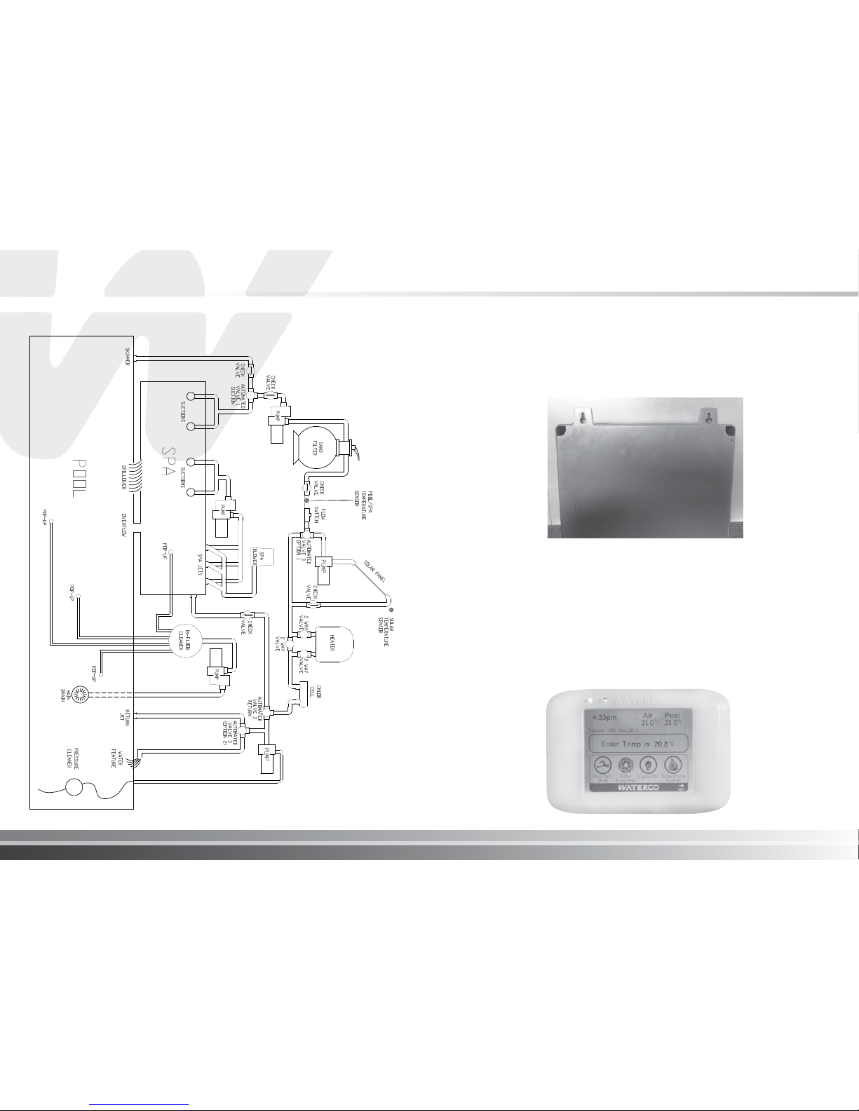
vii. The plumbing diagram below is intended to be used as a general guideline and is not a
complete plumbing schematic for the pool.
viii. We recommend the air sensor be installed for user convenience and for the freeze protection
feature for the lter, valves or aux outputs.
Waterco Aquamaster
I pg 05
Hydraulics diagram
INSTALLING EQUIPMENT
a. Aquamaster Control Enclosure
Install the Aquamaster control enclosure in a protected location out of direct sunlight. At top rear
of the control panel locate two keyhole xing points. Mount two pan head type screws at 216mm
centres using a spirit level on an adequately stable vertical surface. Align the screw heads with the
keyhole xing points and allow the enclosure to slide down on the screws.
To access the Aquamaster for connection of cabling and sensors locate the front panel of
Aquamaster and screw well in each corner. To open the panel, insert a at blade screw driver and
half turn anti-clock wise to release the spring loaded locking pin. Ensure the pins are fully released
prior to opening the hinged front panel.
b. LCD Control Panel
Indoor Installation
The LCD Control Panel is suitable for indoor mounting. The back plate of the LCD Control Panel is
removable and is easily mounted utilising methods similar to installing a standard Australian wall
switch plate with mounting centers of 76mm.

Waterco Aquamaster
I pg 07
Outdoor Installation
The LCD Panel is able to be mounted outdoors within a suitably rated weatherproof enclosure.
c. Temperature Sensors
The Aquamaster has a number of sensors for pool, roof and air temperature monitoring.
Pool Sensor:
a) The pool water temperature sensor should be installed prior to any heater or solar and will
display either the pool or the spa temperature, depending on the current operation of the pool.
b) Immediately after the lter drill a 9.5mm hole in the side of the line as shown in the image below.
Insert the special plug into the hole and rotate home.
c) Insert the sensor holder by pushing into the plug fully up to the head. This is a tight t to ensure
sealing. Lubricate with soap if necessary but do not use mineral oil or grease.
d) Strap lead rmly to pipe to prevent any strain on the sensor holder or lead entry.
e) The sensor should not be installed on top of any pipe work coming from the pump as it is
exposed to sunlight and accidental physical damage may occur. It should be installed on an
inside elbow of the pipe work (as shown). This will eliminate heating of the sensor by sunlight –
giving inaccurate readings, and also minimise the risk of damaging the sensor by pool users.
Pool Sensor Installation
Incorrect Position
Correct Position
Roof Sensor (required if a solar heating system is installed):
a) If the sensor lead is to be concealed, e.g. underground, make sure it is run through a conduit to
ensure easy removal if service is required.
b) To take cable to the roof it should be tied off neatly with electrician’s cable ties to one of the solar
pipes.
c) The roof sensor is supplied housed in a probe holder. This holder should be xed to the roof in
a small pad of adhesive the same angle as the solar absorber. This is to ensure the sensor will
measure the actual roof temperature and the reading will be unaffected by the cooler pool water
when the solar system turns on.
d) The sensor must always be located so it is in the sun at the same time as the solar absorber
array; otherwise incorrect readings will be made. This can happen when parts of the absorber
are in the shade, and the sensor is still receiving full sunlight.
e) The sensor should be located at least 600mm from the top of the roof to eliminate any wind chill
factor, 1m from the sides of the roof, and at least 500mm from the solar absorber array to read
a constant accurate roof temperature.
Keep the adhesive clear of the cable and also from the top of the holder to facilitate the removal
of the probe holder if it should require future service. Suitably clip the lead along its run, to prevent
any strain to the sensor holder.
Waterco Aquamaster
I pg 09
Sensor orientation on
curved tiles (front view)
Sensor should be pointing up the
roof and secure with silicone on
the plastic body only
Correct Sensor Position
Sensor orientation
(side view)
Incorrect Sensor Position
The sensor should be orientated such that it lies on the crest of the roof tiles and not in the troughs.
This eliminates water being trapped in the silicon glue that holds the sensor in place, and giving
erroneous readings. The roof sensor should also be positioned so that it points up the roof tiles (as
shown above).
Air Sensor
Mount the air sensor outdoors and out of direct sunlight.
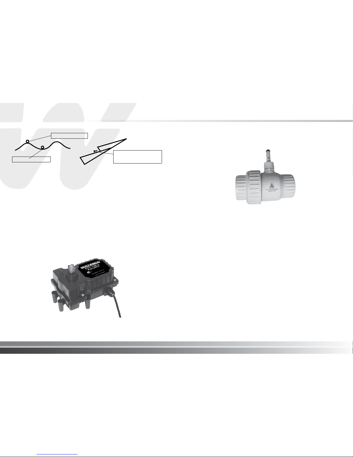
d. Valve Actuators
The Aquamaster system is optimized to operate Waterco FPI valve actuators and should be
installed in consultation with the product installation and operating instructions.
e. Flocheck Valve (optional)
Waterco recommend the Aquamaster system is tted with the optional Waterco Flocheck valve and
should be installed in consultation with the product installation and operating instructions.
FUNCTIONS
The Waterco Flocheck valve has a number of essential functions:
1. As a normal pre-loaded check valve to prevent pool water backwashing the lter on shutoff or
drain down.
2. As a pump protection device for when there is no lter water ow. Power is switched off by the
solar controller through integration with the Flocheck valve, stopping the pump immediately.
3. As a warning device to highlight the water ow below recommended levels for solar pool system
operation.
4. As an adjustable ow switch which can be tailored to the customer’s requirements.
Waterco Aquamaster
I pg 11
INSTALLATION
1. The ‘Flocheck’ valve should be placed at the end of a straight length of pipe at least 500mm long
and before the integrated take-off point. Mounting the valve in this position assumes the water
ow is not turbulent at the point of sensing. This is important in order to avoid multiple starts of
the boost pump / integrated pump.
2. The valve can be installed in horizontal or vertical pipe. The probe stem should be upright if
installation is in the horizontal position for correct action.
3. The valve must be tted to the direction of the water ow as indicated on the valve body.
4. WARNING: when gluing into the line, use cement sparingly so ap is not inadvertently glued in
the closed or open position.
5. Remove small bridging plug from the socket of the controller (if present). Push in the plug of the
‘Flocheck’ valve to the controller.
WARNING: The sensing switch in the unit is rated in milliamps NOT AMPS and will not directly
switch 240 VAC power.
FLOW SENSING
PRE-SET THRESHOLD FLOW
The valve has a factory setting ‘switch-on’ threshold water ow of 60 litre/min and ‘switch-off’ (30
l/min) threshold point. To change the threshold point the following procedure is to be performed.
(a) Holding the sensing stem to prevent movement, slightly loosen the knurled lockseal nut.
(b) Slide the sensing stem to the new position required to accept the water ow characteristics of
that particular lter system. The threshold ow is increased by pulling the sensing stem further
out from the body and conversely decreased by pushing the stem into the body.
(c) Lock the stem into position with the knurled lock seal nut.
(d) Check correct operation of the ow switch. With the integrated pump operating, stop and start
the lter system several times.
If the pump continues to operate when there is no water ow, check the functionality of the hinged
valve inside the unit for correct operation and debris.
WARNING: when gluing into the line, use cement sparingly so ap is not inadvertently glued in the
closed or open position.
Remove small bridging plug from the socket of the controller (if present).
Push in the plug of the ‘Flocheck’ valve to the controller.
WARNING: the switch in the unit is only rated in milliamps NOT AMPS and will not directly switch
to 240 VAC power. Unit is to be connected to the terminal provided in the Aquamaster.
ELECTRICAL
Ensure power is disconnected prior to wiring Aquamaster.
• Follow all statutory and local wiring and installation regulations
• Use copper conductors only
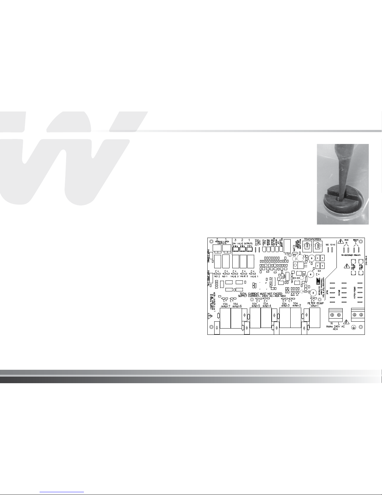
The Aquamaster requires both high and low voltage connections.
To gain access to the wiring compartment, insert a at blade
screw driver and half turn anti-clock wise to release the spring
loaded locking pin in each corner. Ensure the pins are fully
released prior to opening the hinged front panel. The hinged
panel may be removed by lifting it upwards from the hinge
pins. All connections will be made to the printed circuit board
(PCB) inside the control box. These connections include mains
supply, hard wired inputs and outputs, actuators, sensors and
dry contacts for heater control. When cabling is wired into the
Aquamaster Control Enclosure all cable entry points must be
sealed to prevent ingress of moisture.
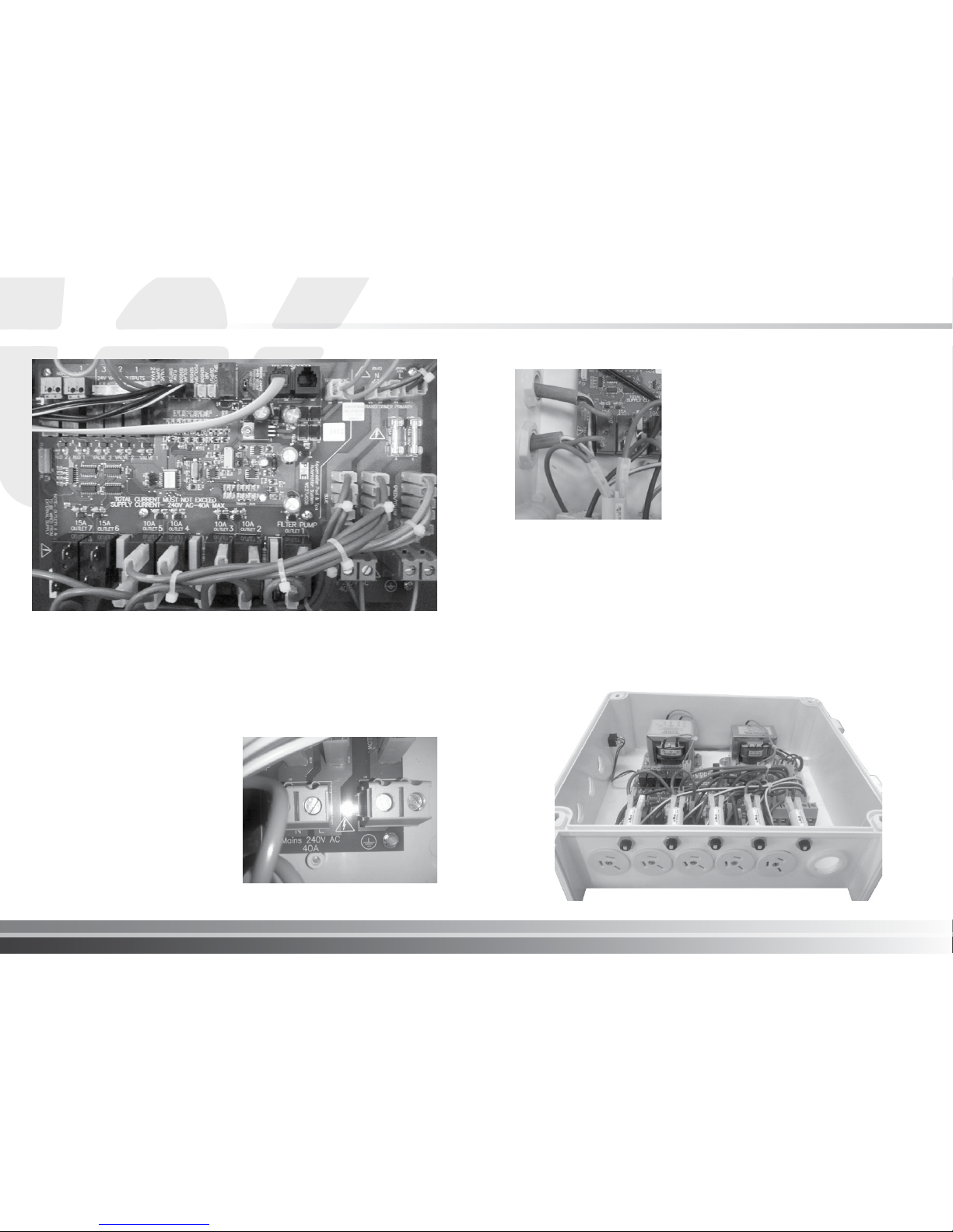
Aquamaster Control PCB layout
Waterco Aquamaster
I pg 13
Aquamaster Control PCB image
System Earthing
An earth terminal is located within the compartment of the Aquamaster. Connect an earth wire from
the primary electrical supply to the earth terminal.
Input Power Wiring
The Aquamaster requires 240VAC, 40amp
maximum input power to operate the control
logic circuits, low voltage devices and hard
wired socket outlets. This power must be
supplied from a maximum 40amp circuit breaker
with earth leakage protection in accordance
with the wiring rules. It is recommended surge
protection be tted in areas of unreliable power
supply or prone to lightening strikes.
The mains power cables should utilize the
threaded cable entry point provided on the
bottom plate right hand side of the enclosure
to ensure electrical segregation between low
voltage and extra low voltage cabling.
Wiring 15amp switched relays
The Aquamaster features 2 x 15amp dry contact switching
relays which may be used to operate equipment with an
electrical rating of up to 15amps each. Ideally, a separate
electrical supply with circuit breaker protection should be
connected to each 15amp switching relay numbered 6 & 7
on the PCB.
These power cables should utilize the threaded cable entry
points provided in the side of the enclosure to ensure
electrical segregation between low voltage and extra low
voltage cabling.
Electrical Specification
Input Rating: 240VAC, 50Hz, 40amp max
Output Ratings:
Relays: 5 x 10A @ 240VAC max sockets with max total output of 40amps
2 x15A @ 240VAC max dry contacts
Valves: 24VAC, 1A max with max total loading of 2.5amps
Heater: 24VAC, 1A max dry contacts
Enclosure Rating: IP23
LCD Display Rating: Not IP rated - if mounting outdoors the unit must be housed in a
suitably rated IP enclosure
Approval No.: SGSEA/NSW26531
 Loading...