

WaterClinic LOTUS-75TC, LOTUS-75SS User Manual

Innovation has a name.
LOTUS-75TC
LOTUS-75SS
Reverse Osmosis User Manual
Ters Osmoz Kullanma Kılavuzu


ENG 1
Dear customer,
Thank you for purchasing a "Waterclinic by A.O. Smith" branded water purier!
You are now the owner of water treatment equipment produced by the world’s leading
manufacturer of water treatment systems. This equipment produces pure water that can
be consumed directly, providing you with a cleaner and healthier source of drinking water.
Please read this user manual carefully before you install and operate your
"Waterclinic by A.O. Smith branded" water purier. To achieve maximum efciency this user
manual provides detailed instructions regarding the installation of your water purier as
well as information related to the proper operation and maintenance of your water purier.
The installation should only be handled by professionals authorized by A.O. Smith
Su Teknolojileri A.Ş.
Spare parts used for maintenance and replacement lter should be approved
by A.O. Smith Su Teknolojileri A.Ş. before they are installed.
Any degradation of performance caused by the use of spare parts or lters that have not
been approved by A.O. Smith Su Teknolojileri A.Ş. will not be covered by our warranty.
If you experience any difculties during installation or operation, please contact your local
distributor to have them carry out repairs or maintenance on your equipment.

ENG 2
CONTENTS
İÇİNDEKİLER

ENG
SAFETY CONSIDERATIONS 4
PRODUCT DESCRIPTION 7
Brief Introduction 7
Description of Components 7
Electrical Diagram 8
Water Route Map 8
Technical Specications 9
Functions of Main Components 9
Functions of Accessories 10
Water Purier Features 10
INSTALLATION METHODS 10
Pre-Installation Preparations 10
Instructions for Proper Installation 11
Installation Notes 13
ADJUSTMENT METHODS 14
LED DISPLAY FUNCTIONS 14
OPERATION METHODS 15
MAINTENANCE AND REPAIR 15
Flushing the RO Membrane 15
Filter Replacement Intervals 15
Filter Replacement Methods 16
Notes 18
PACKING LIST 18
AFTER-SALES SERVICE 18
TROUBLESHOOTING GUIDE 19
TR
GÜVENLİK UYARILARI 22
ÜRÜN TANITIMI 25
Kısa Tanıtım 25
Su Arıtma Cihazının Ayrıntılı Proli 25
Elektrik Şeması 26
Su Akış Şeması 26
Teknik Bilgiler 27
Ana Bileşenlerin İşlevleri 27
Aksesuarların İşlevleri 28
Su Arıtma Cihazının Özellikleri 28
KURULUM TALİMATLARI 28
Kurulum İçin Ön Hazırlık 28
Doğru Kurulum için Uyulması Gereken Talimatlar 29
Kurulum Notları 31
AYARLAMA YÖNTEMLERİ 32
LED EKRANIN İŞLEVLERİ 32
KULLANIM UYARILARI 33
BAKIM VE ONARIM 33
RO Membranın Yıkanması 33
Filtre Değişim Aralıkları 33
Filtre Değişim Yöntemleri 34
Uyarılar 35
ÜRÜN KONTROL LİSTESİ 36
SATIŞ SONRASI SERVİS 36
ARIZA GİDERME KILAVUZU 37
YETKİLİ SERVİSLER 38
BAKIM KARTI 39 - 41
MONTAJ KONTROL KARTI 40
GARANTİ BELGESİ 42
ENG 4
Safety Considerations
(Be sure to read and remember these safety considerations)
Make note of the following safety precautions In order to avoid property damage and harm to you and others.
•Ignoring the following safety precautions could result in risky situations for you, your water purier and your environment.
Warnings
If you ignore contents in this section, it may cause permanent damage to the water purier or cause serious property damage.
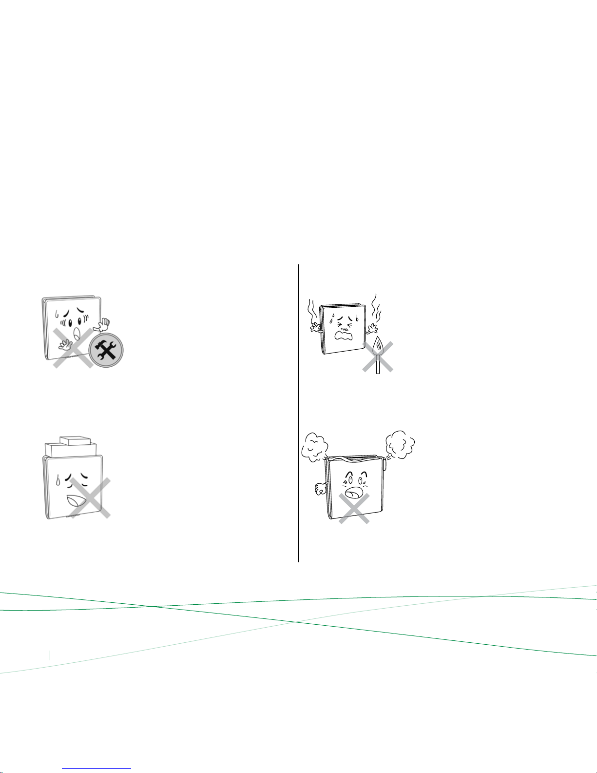
Do not disassemble or modify this water
purier on your own!
Unauthorized disassembly or modication
of the machine could lead to machine
malfunctions or leakage accidents. Please
check with the store where you purchased
this product for product consultation in order
to arrange for repairs.
Do not put the water purier close
to a source of ames!
Do not put the water purier near a source
of ames or a place where the temperature
is too high as this may cause deformation or
melting of the machine, causing damage or
leakage, which could lead to serious bodily
and property damage.
Do not put heavy objects on the water
purier!
Placing heavy objects on the water purier
may cause damage to the water purier’s
external cover or internal components, which
in turn could lead to leakage, equipment
malfunctions or even serious property
damage.
Do not place any objects on top of your
water purier!
Obstructing the heat dissipation may lead to
machine damage or res.
ENG 5
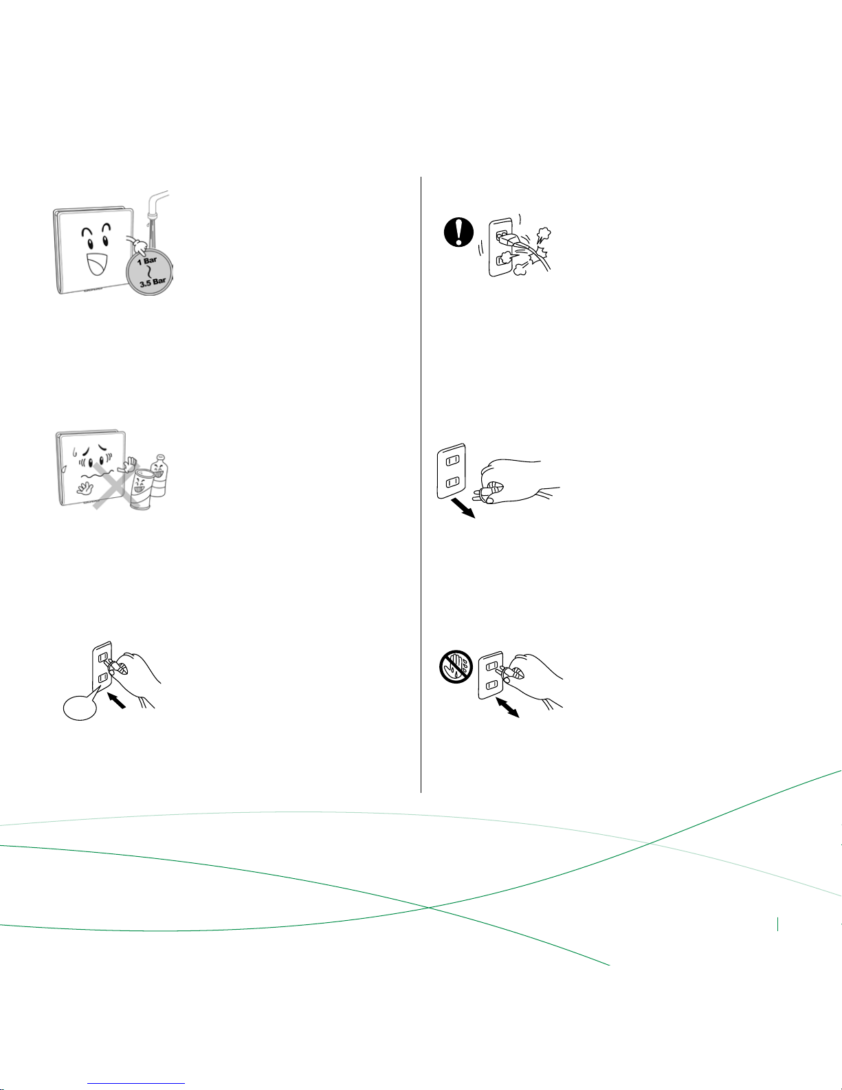
Do not use this water purier under high
water pressure conditions!
Operating under high pressure conditions
may cause the water purier pipes to rupture,
resulting in leakage, the machine working
improperly, or even serious property damage.
Recommended inlet pressure is
1 Bar to 3.5 Bar.
Do not use a power source exceeding
the equipment’s specied value. Use only
220V AC power!
The electrical current supplied to your
equipment by the outlet must not be greater
than the specied value; otherwise it may
lead to the overheating of your equipment
or re.
Do not touch the power plug with wet hands!
It may lead to electric shock.
Do not damage the power cord
or the outlet!
Doing so may lead to electric shock, short
circuiting or re.
Do not let the machine come in contact with
corrosive materials!
These materials could corrode the outer cover
and adversely affect various parts of the
equipment. Toxic and hazardous compounds
could penetrate the water purier pipes,
causing contamination of the water or
leakage, which in turn may cause personal
damage or property damage.
The equipment must be disconnected from
the power supply during installation
and repairs!
Otherwise it may lead to electric shock.
220 V
ENG 6
Warnings
If you ignore contents in this section, it may cause permanent damage to the water purier or cause serious property damage.
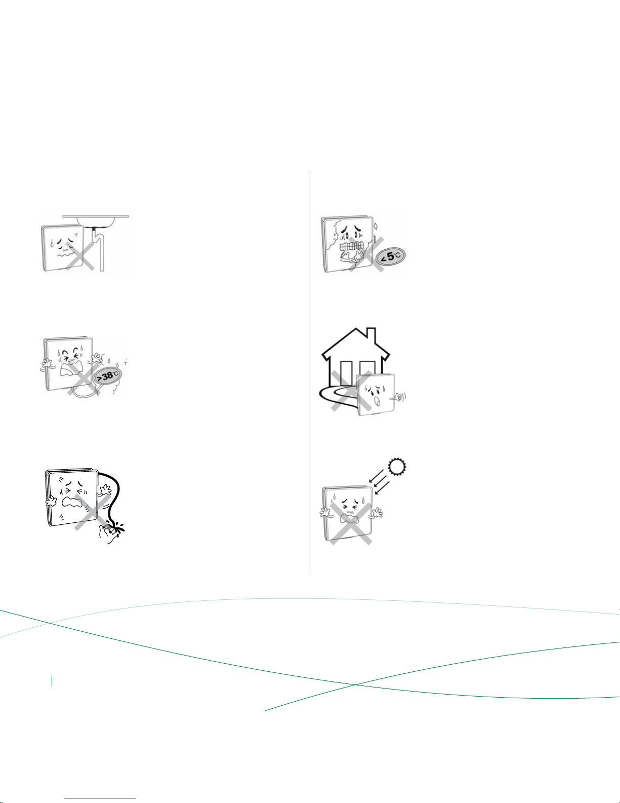
Do not use the water purier when the sewer
is blocked up!
If the purier is used while the sewer is
blocked, it may cause waste water to back
up into the purier and pollute the water
and parts inside.
Do not place the water purier under direct
sunlight!
Placing the water purier under direct
sunlight for a certain period of time may
create a breeding ground for microorganisms;
decreasing the output water quality
and potentially causing the internal
components of the water purier
to become contaminated.
The waste water discharge pipe and
waste water rationing device cannot be
blocked!
When the waste water discharge pipes and
waste water rationing devices are obstructed
or clogged, it may lead to high levels of TDS
efuent, the RO membrane may get blocked
or the water purier may not work.
Do not use in conditions under 5°C!
If the ambient temperature falls below 5°C,
please be sure to take measures to prevent
freezing, such as turning on a heater or air
conditioner to prevent leakage or cracked
pipes caused by water freezing inside
the equipment.
Water purier inlet water temperature
should not exceed 38°C!
If the inlet water temperature is over 38°C,
it will damage the reverse osmosis membrane
leading to membrane failure.
Do not use this water purier outdoors!
If this water purier is used outdoors, it can
lead to accelerated aging of the
water purier pipes and parts, which can
cause leaking or machine failure.
ENG 7
Brief Introduction
This equipment utilizes the current, most advanced international
RO technology. RO technology relies on the articial reversing
of the naturally occurring osmosis phenomena. The RO membranes have
pores with a diameter of 0.0001 micron (0.1 nm), so they can effectively
remove bacteria, viruses, heavy metals, pesticide residue, and other harmful
substances from the water. Produced water is fresh, pure and suitable for
direct use.
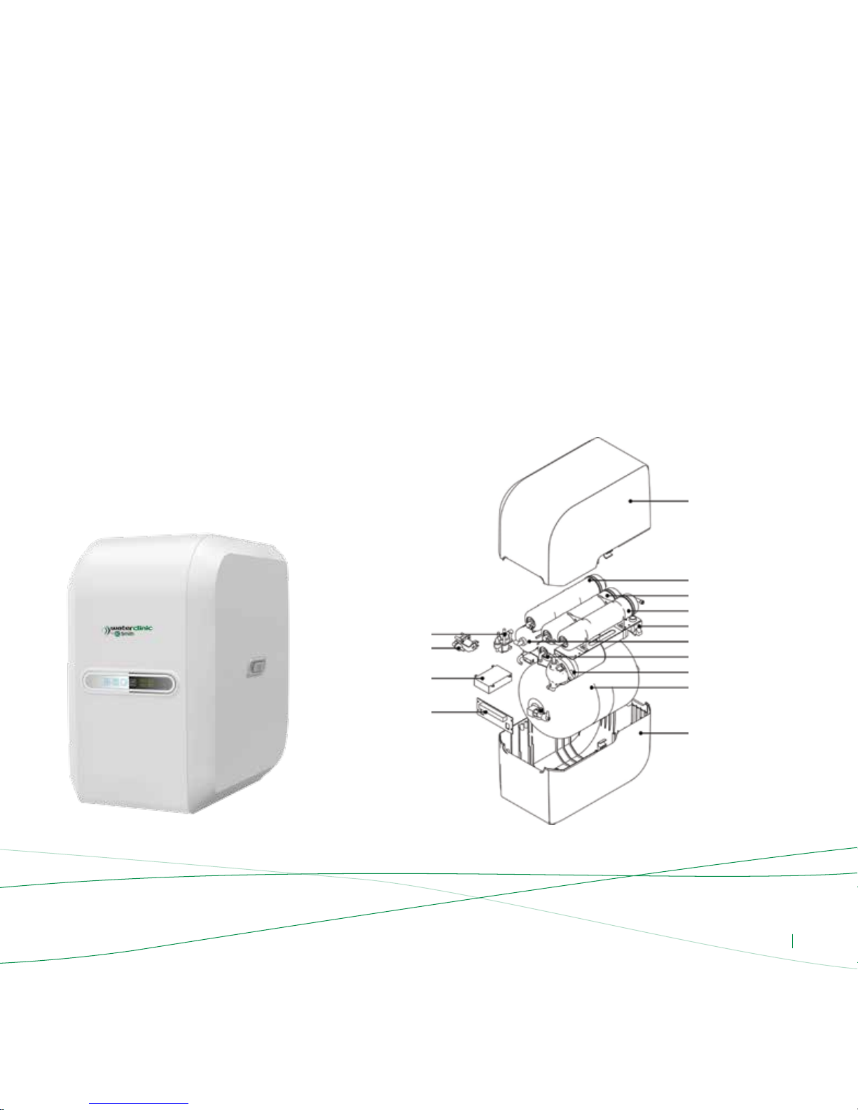
Description of Components
Product Description
Diagram 1
Upper cover
Post activated carbon lter
1µ m PP lter
5µ m PP lter
Low pressure switch
RO Membrane
GAC Filter
Pump
2.5 Water tank
Bottom cover
Combination valve
24V Small square solenoid
Computer control box
Display board
Lotus-75TC
ENG 8
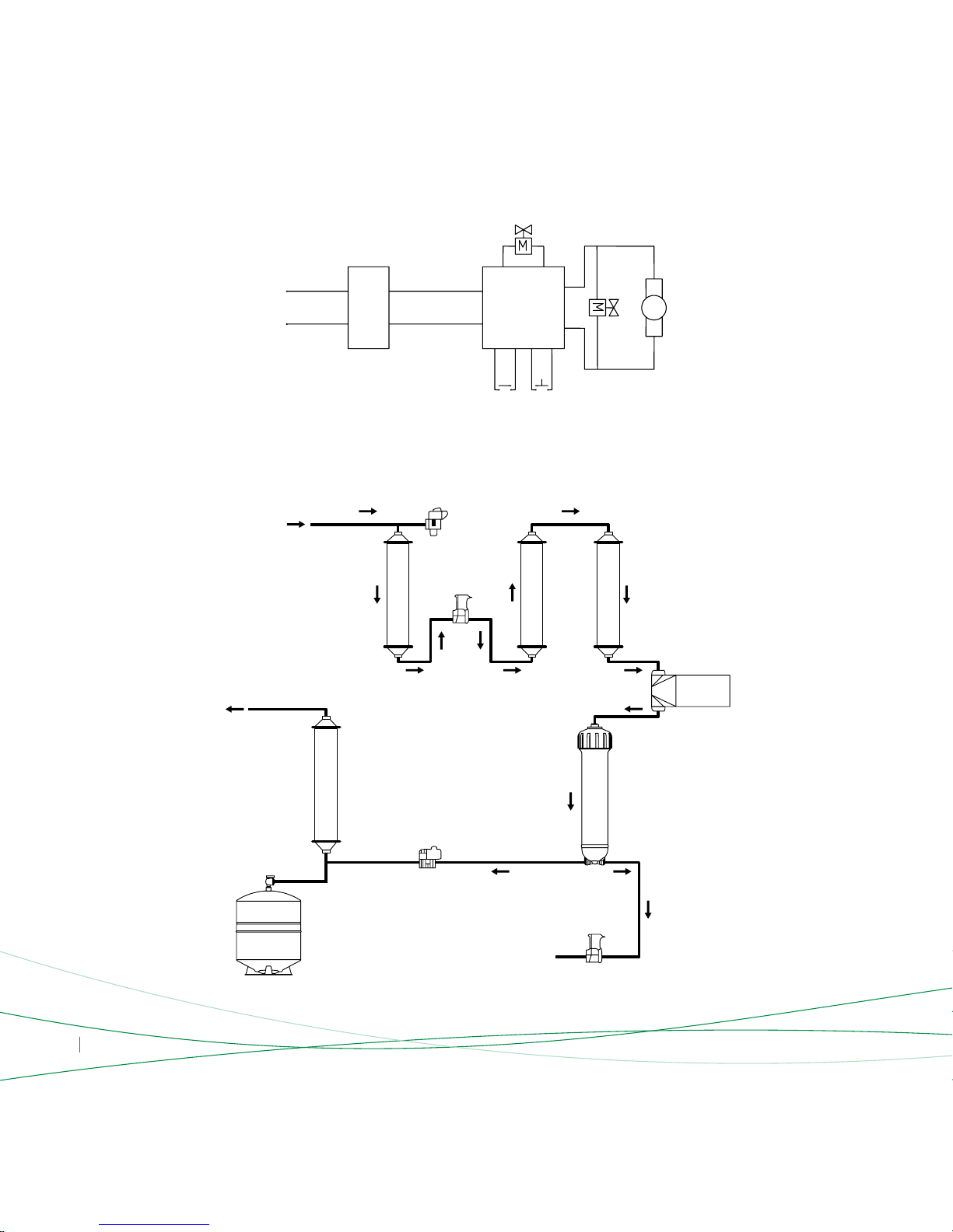
Electrical Diagram
Diagram 2
220 V 24 V (36 V) Computer box
Low pressure switch High pressure switch
Pump
Adaptor
Combined solenoid switch
Diagram 3
Combined solenoid valve
Pure water outlet
Inlet water
Waste water
Post activated carbon
lter
RO Membrane
Pump
High pressure
switch
Water tank
Inlet
water
solenoid
valve
Low pressure switch
5 Micron
PPF
1 Micron
PPF
GAC lter
Water Route Map

ENG 9
Functions of the Main Components
The standard conguration of the water purier that utilizes the current,
most advanced international RO technology is as follows:
• The rst stage is a 5-micron PP lter (Sediment):
The pores on the aperture within the PP lter is 5 microns wide so it
can effectively lter rust, sand, other larger particles and solid impurities
suspended in the water.
• The second stage is a granular activated carbon lter:
The lter effectively absorbs chlorine, mould, disinfection by-products,
odors, discolorations and other materials suspended in the water.
• The third stage is a 1-micron PP lter (Sediment):
This lter further removes small particles within in the water, suspended
solids, colloids, etc.
• The fourth stage is the RO membrane:
The membrane has an aperture of 0.0001 micron (0.1 nm) that reduces
bacteria by 4,000 fold, reduces viruses by over 200 fold, so you can
effectively remove bacteria, viruses, heavy metals, pesticide residue,
and other harmful substances contained in your water supply .
• The fth-stage is a post-activated carbon lter:
This lter regulates the taste of water and keeps the water fresh .
Note: This machine also has an optional conguration
which is as follows:
Pretreatment Filter: KDF two stage lter, KDF three stage lter, sintered
activated carbon lter Post-lter: Alkaline lter, infrared mineralization
activated carbon lter, alkaline sterilization lter, sterilizing lter.
Post-lter: Alkaline lter, infrared mineralization & activated carbon lter,
post alkaline sterilization resin lter, post sterilization resin lter
Note: the parameters above may change due to product improvements, but the product name plate shall remain the same. TDS refers to inuent total dissolved solids.
Note:
0.1 MPa = 1.02 Kg/cm
2
= 14.5Psi
1 Psi = 0.07 Kg/cm
2
1 Gallon = 3.785 Liters
75 GPD = 75 Gallons/Day = 284 Liters/Day = 197 Milliliters/Minute
Technical Specications
Model No.
Voltage
Suitable Water Pressure
Operating Pressure
Inlet Temperature
Maximum Daily Water TDS Value
Flushing Method
Electric Shock Protection Type
Dimensions
Weight
Suitable Water Quality
Power Rating
Maximum Daily Water Production Volume
Tank Volume
AC 220-240V 50HZ
36 W
0.1 ~ 0.35 MPa
0.6 ~ 0.8 MPa
5 ~38˚C
≤1000 PPM
Auto Flushing
75 Gallons, approximately 284 Liters
2.5 Gallons, approximately 9.5 Liters
Type II
Munical tap water meeting the GB5749-2006 standarts
LOTUS - 75SS LOTUS - 75TC
270 × 410 × 420 mm
11 kg

ENG 10
Pre-Installation Preparations
• Choose the location where the water purier will be installed
• Conrm the availability of the various tools required
for installation
• Conrm that you have all the connectors required for installation
• Make sure to turn off the water supply and electricity before
commencing installation
Functions of Accessories
• Storage Tank: Used to store water ltered by the water purier.
• High Pressure Pump: Boosts pressure to create a stable environment
for the RO membrane.
• Low Voltage Switch: Prevents pump idling. When the inlet water
pressure is less than 0.03 MPa or when the inlet water stops,
the low-voltage switch automatically shuts off the power source
so the machine comes to a halt.
• High-Voltage Switch: Prevents pump from overdrive. When the pressure
tank is full or has reached the set pressure level, power supply is
automatically cut off to stop the operation of the machine.
• Inlet Water Solenoid Valve: Connects or cuts off incoming water.
Operating pressure range is less than ≤0.6MPa.
• Check Valve: Also known as a one-way valve, controls the direction
of water ow.
• Auto Flush Solenoid Valve: Automatically ushes the reverse osmosis
membrane.
• Computer Control Box: Converts 220V AC to 24V DC (the machine’s
safe operating voltage).
Water Purier Features
• Low Noise: This machine’s imported parts offer low noise,
few vibrations, long service life, operational quality and reliability;
• Automatic Control System: The system controls the whole water
production process, such as stopping automatically when there is no
inlet water or when the tank is full;
• Auto Flush Function: The system can automatically control the water
auto ush process for the RO membrane to ensure more reliable
and safe operation.
Installation Methods
Our company recommends that your water purier is installed by trained professionals as the installation process is somewhat complex and requires the
use of various tools. However, if you decide to install the purier yourself, please refer to the following steps and diagrams:
Adjustable Spanner
Drill
6.2 mm Drilling Bit
Hole Saw φ14 mm
Phillips and Flathead Screwdrivers
Scissors
14 - 16 mm Wrench
19 - 21 mm Wrench
Needle Nose Pliers
1
1
1 (Waste water hole)
1 (High-speed steel or marble hole saw)
1 of each
1 pair
1
1
1
ENG 11
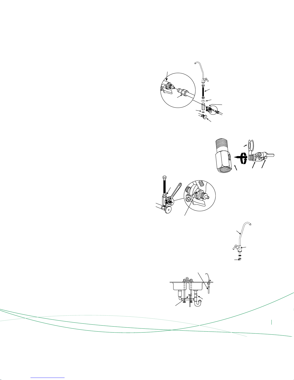
Instructions for Proper Installation
• Method of installing the inlet water metal hose and 3-way inlet waterjoint:
(If the metal hose diameter is 9 mm the 3 - way inlet water joint must be
purchased separately) First, close the inlet water valve. Screw off
the metal hose. Remove the 3-way inlet water joint from the water purier
accessories box, screw one end of the inlet water 3-way joint onto the inlet
water valve outlet. One end of the unscrewed metal hose should be screwed
into the 3-way inlet water joint using the screw nut (See Diagram 4)
• Method of installing the 3-way inlet water joint and inlet water ball valve:
Take out the inlet water ball valve from the water purier accessories
box, wrap one end of the external threads on the ball valve with appropriate
teon tape (See Diagram 5). If you have silica gel, spread a little over
the thread and then screw the ball valve into the corresponding hole
of the 3-way inlet water joint (See Diagram 5). Take out the Ø 9mm
water pipe from the accessories box. Using a pair of scissors, cut
a suitable length of pipe and connect one end of the pipe to
the inlet water ball valve (See Diagram 6). Finally screw the nut in place.
• Installation of the osmosis faucet:
Drill a φ14mm hole in an appropriate position on the counter where
the faucet is to be installed. Then take out the faucet from the water
purier accessory box. Begin the installation of the faucet. First put
the osmosis neck on the faucet main body (See Diagram 7), then
lower the main part of the faucet into the hole you have drilled. Put
the spacer on the lower part of the faucet and screw the xed nut on
to the bottom end of the faucet in order to x the faucet to the counter.
Finally, attach the appropriate length of 6mm pipe into the water inlet
connection. Attach the 6mm pipe stopper into one end and place it
on the 6mm nut. Screw it on the bottom of the faucet (see Diagram 8).
If you want to x the faucet on a wall, please use the faucet hanging
piece (when installing be sure to tighten the joints to prevent leakage).
• Installation of the waste water pipe:
Drill a small hole into the sink drain pipe using a φ 6mm drill. Take
a suitable length of the 6mm water pipe and lay one end just inside
the drilled hole (See Diagram 8), put some silica gel where the 6mm
pipe and the drain pipe connect to prevent leakage. Use a cable tie to x
the waste water pipe to the drain pipe (for large ow water puriers;
you will need to insert a waste water clip into the drilled drain pipe hole)
Diagram 4
Faucet water hose
connector
Washer
Washer
Inlet water valve
Inlet water valve
Screw nut
3-Way inlet water joint
Diagram 5
3-Way inlet
water joint
Inlet water
ball valve
Teon tape
Water pipe
connection
Diagram 6
9mm Ball valve
Inlet water
3-way
joint
Diagram 7
Osmosis faucet
Main part of faucet
Inlet water
connection
Diagram 8
Pure water pipe
Hot
Cold
Inlet water ball valve
Waste water hole
ENG 12
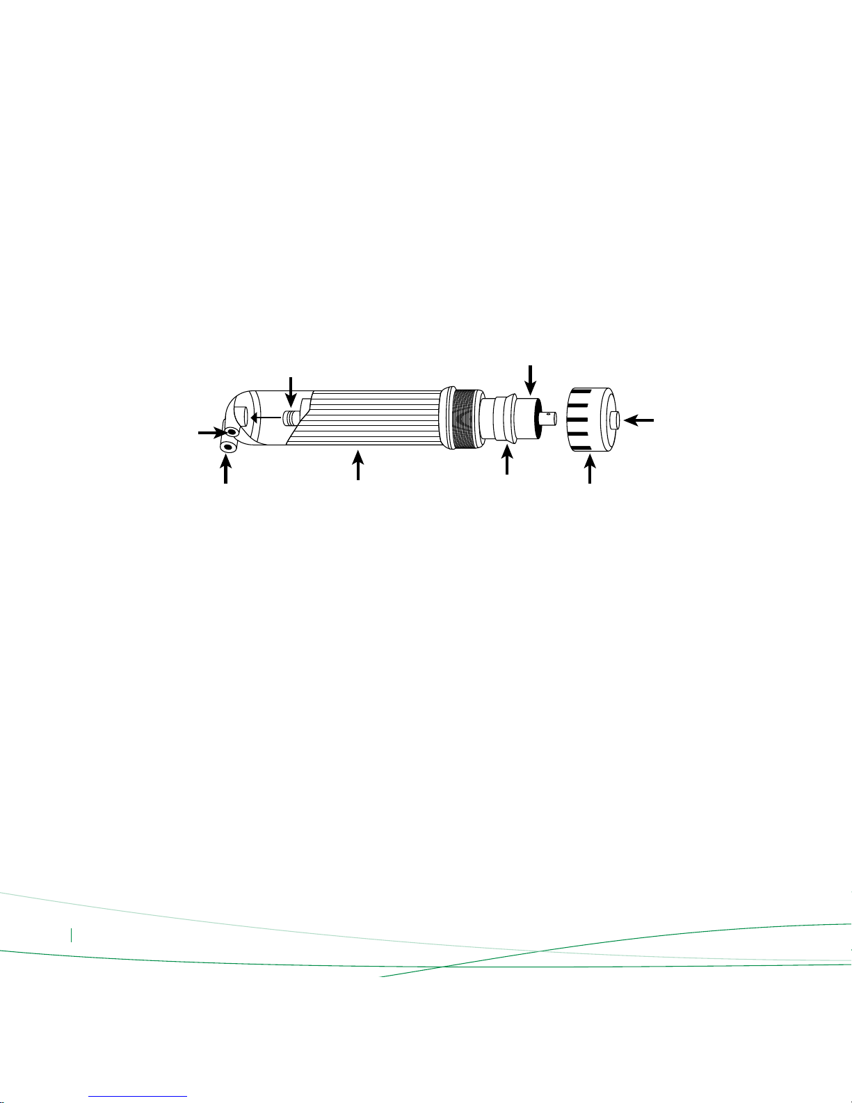
• RO Membrane installation
-Installation of the regular RO Membrane (Model Lotus 75TC):
First take the water purier out of its package. Open the water purier’s
outer cover. Unscrew the membrane shell cover inlet water connection
and take out the inlet water pipe. Then use the membrane shell wrench
to unscrew the membrane shell cover. Take the RO membrane out from
its package. Place the end of the membrane with the O-ring into
the reverse osmosis membrane shell (See Diagram 9) and push it in.
Finally, screw the membrane shell cover back on and use the membrane
shell wrench to tighten the membrane shell cover. Connect the inlet water
pipe into the inlet water connector on the membrane shell and screw in
the nut. Place the membrane shell card into the large single clip available
and attach the water purier cover back on.
Warning Concerning Lotus 75TC:
• You should pay attention to the direction of the RO membrane during
installation.
• When installing the RO membrane; you should rst make sure that one
end of the membrane has an O-ring;
• During installing, be sure to put the end with the O-ring into the end
of the membrane shell with the pure water connection. If you install
the reverse osmosis membrane correctly, you will only need a little force
to mount it into the membrane shell. If you encounter too much
resistance, please do not force the reverse osmosis membrane into
the membrane shell. Doing so may cause permanent damage to the
membrane shell or membrane components (the membrane
manufacturer does not assume responsibility for returned components
due to damages incurred during installation).
• Damage to the membrane shell and reverse osmosis membrane
components inicted as a result of the abovementioned reasons is not
covered under the water purier’s warranty.
- Installation of the side-stream RO Membrane (Model Lotus 75SS):
Unscrew the membrane shell cover. Take the inlet water pipe out from
the membrane shell cover (see diagram 12).Then, using the lter wrench,
open the membrane shell cover. Remove the membrane from
its packaging. Then put the end with 4 O-rings into the RO membrane
shell (see diagram 10). Finally, screw the membrane shell cover back on
and use the membrane shell wrench to tighten the membrane shell cover.
Connect the inlet water pipe into the inlet water connector on
the membrane shell and screw in the nut. Then place the membrane shell
card into the large single clip available and attach the water purier cover
back on.
Warning Concerning Model Lotus 75SS:
• When installing the RO membrane; you should rst make sure that one
end of the membrane has an O-ring;
• During installing, be sure to put the end with the O-ring into the end
of the membrane shell with the pure water connection. If you install
the reverse osmosis membrane correctly, you will only need a little force
to mount it into the membrane shell. If you encounter too much
resistance, please do not force the reverse osmosis membrane into
Diagram 9
Pure water
O-ring
Membrane shell
RO Membrane
Waste water
Sealing ring
Inlet water
Membrane
shell cover

ENG 13
the membrane shell. Doing so may cause permanent damage to the
membrane shell or membrane components (the membrane
manufacturer does not assume responsibility for returned components
due to damages incurred during installation).
• Damage to the membrane shell and reverse osmosis membrane
components inicted as a result of the abovementioned reasons is not
covered under the water purier’s warranty.
• Installation of the pipes
- Before installing the pipes, make sure that the surface of the pipes is
smooth. Cut the pipe on the front-end perpendicular with the length
of the tube with scissors and then make the cut section round before
inserting inside (see diagram 11 for the correct way of cutting);
If the pipe is not round, but still elliptical and then is inserted inside,
it will damage the O-ring and cause water leakage.
- While installing the water pipe, it will get stuck at the rst bayonet
before the pipe is completely seized by the connectors. Push it hard
until the pipe reaches the end. If the pipe cannot be inserted into the
deepest end, it probably breaks away when transferring the pressure.
(see diagram 12)
- When removing the water pipe, push in the jack catch rst and then
pull out the pipe (see diagram 13).
- After the water pipes have been connected, safety clips should be
installed on the quick ttings to avoid the ttings to break away.
(see diagram 14)
Installation Notes
• If the power cord wiring needs to be longer, extend the cord
according to the wiring requirements and use an φ8mm pinched tube
to wrap around the connection. Later, wrap insulating electrical tape on
the outside surface. Do not place the cord on the oor. The cord
should be suspended in the air or should follow a path above ground.
• During installation, make sure that there is no electrical wiring or water
pipes embedded inside the walls where you will do the drilling.
Large O-ring
Large O-ring
Small O-ring
Membrane shell
Waste water
Inlet water
Inlet water
RO outlet water
Membrane shell cover
Diagram 10
Right way to cut pipes Wrong way to cut pipes
Diagram 11
Diagram 14
Diagram 12
Diagram 13
Clip (Before installation) Clip (After installation)
 Loading...