

WaterCare TotalCare Series, CareSoft Elite Series, CareSoft Pro Series Installation Instructions & Owner's Manual
TotalCare®, CareSoft Elite® and
®
CareSoft Pro
Water Softeners and Conditioners
Series
For Models:
• TC1
• TC2
• CSE
• CSERC
• CSP
• CSPRC
For Cabinet Models:
• CSEC
• CSPC

TABLE OF CONTENTS
Preinstallation Instructions for Dealers . . . . . . . . . . . . . . . . . . . . . . . . . . . . . . . . . . 3
Bypass Valve . . . . . . . . . . . . . . . . . . . . . . . . . . . . . . . . . . . . . . . . . . . . . . . . . . . . . . . 4
Installation . . . . . . . . . . . . . . . . . . . . . . . . . . . . . . . . . . . . . . . . . . . . . . . . . . . . . . . . 5-6
Programming Procedures . . . . . . . . . . . . . . . . . . . . . . . . . . . . . . . . . . . . . . . . . . . 7-8
Operating Displays and Instructions . . . . . . . . . . . . . . . . . . . . . . . . . . . . . . . . . .9-10
Start-up Instructions for Downflow Units . . . . . . . . . . . . . . . . . . . . . . . . . . . . . . . 11
Start-up Instructions for Upflow Units . . . . . . . . . . . . . . . . . . . . . . . . . . . . . . . . . . 12
Troubleshooting Guide . . . . . . . . . . . . . . . . . . . . . . . . . . . . . . . . . . . . . . . . . . . . 13-17
Replacement Parts . . . . . . . . . . . . . . . . . . . . . . . . . . . . . . . . . . . . . . . . . . . . . . . .18-27
Specifications . . . . . . . . . . . . . . . . . . . . . . . . . . . . . . . . . . . . . . . . . . . . . . . . . . . . 28-29
Warranty . . . . . . . . . . . . . . . . . . . . . . . . . . . . . . . . . . . . . . . . . . . . . . . . . . . . . . . . . 30
Quick Reference Guide . . . . . . . . . . . . . . . . . . . . . . . . . . . . . . . . . . . . . . . . . . . . 31-32
YOUR WATER TEST
Hardness _____________________ gpg
Iron __________________________ ppm
pH ___________________________ number
*Nitrates ______________________ ppm
Manganese ___________________ ppm
Sulphur _______________________ yes/no
Total Dissolved Solids ___________
*Over 10 ppm may be harmful for human consumption.
Water conditioners do not remove nitrates or coliform bacteria,
this requires specialized equipment.
Your TotalCare, CareSoft Elite and CareSoft Pro Series water softeners and conditioners are precision built, high
quality products. These units will deliver conditioned water for many years to come, when installed and operated
properly. Please study this manual carefully and understand the cautions and notes before installing. This manual
should be kept for future reference. If you have any questions regarding your water conditioner, contact your local
dealer or the manufacturer at the following:
1900 Prospect Court • Appleton, WI 54914
Phone: 920-739-9401 • Fax: 920-739-9406

PREINSTALLATION INSTRUCTIONS FOR DEALERS:
The manufacturer has preset the water treatment unit’s sequence of cycles, cycle times, salt dose, exchange capacity and
salt dose refill time.
The dealer should read this page and guide the installer regarding hardness, day override, time of regeneration,
service alarm and buzzer alarm settings before installation.
For the installer, the following must be used:
• Program Installer Settings ... Hardness, Day Override (preset to 6 days), Time of Regeneration (preset to 2
a.m., with brine tank refill to occur four hours prior; see Operating Displays and Instructions for more details),
Service Alarms (preset to “OFF”) and Buzzer Alarm (preset to start at 6 a.m. and end at 10 p.m.)
• Read Normal Operating Displays
• Set Time of Day
• Read Power Loss & Error Display
• Be sure system and installation are in compliance with all state and local laws and regulations.
For the homeowner, please read Programming Procedures and Operating Displays and Instructions.
During operation, the normal user display is time of day and gallons per minute.
Flow Rate, Vacation Mode, Capacity Remaining and Days to a Regeneration are optional displays but are not normally
used. (Vacation Mode is used only when there will be no water usage for an extended period of time. Once 50 gallons
of water is used, the unit will automatically regenerate that night and resume normal operation.) Each of these can be
viewed by pressing
within 5 minutes, the display returns to a normal user display. Any changes made prior to the 5 minute time out are
incorporated. To quickly exit any Programming, Installer Settings, etc., press SET CLOCK. Any changes made prior to the
exit are incorporated.
NEXT to scroll through them. When stepping through any programming, if no buttons are pressed
If desired, two regenerations within 24 hours are possible with a return to the preset program. To do a double
regeneration:
1. Press the
2. Press and hold the
Once the valve has completed the immediate regeneration, the valve will regenerate one more time at the preset.
REGEN button once. “REGEN TODAY” will flash on the display.
REGEN button for three seconds until a regeneration begins.
3
BYPASS VALVE:
The bypass valve is typically used to isolate the control valve from the plumbing system’s water pressure in order to perform control
valve repairs or maintenance. The 1” full flow bypass valve incorporates four positions, including a diagnostic position that allows
a service technician to have pressure to test a system while providing untreated bypass water to the building. Be sure to install
bypass valve onto main control valve, before beginning plumbing. Or, make provisions in the plumbing system for a bypass. The
bypass body and rotors are glass-filled Noryl
EPDM to help prevent valve seizing after long periods of non-use. Internal “O” Rings can easily be replaced if service is required.
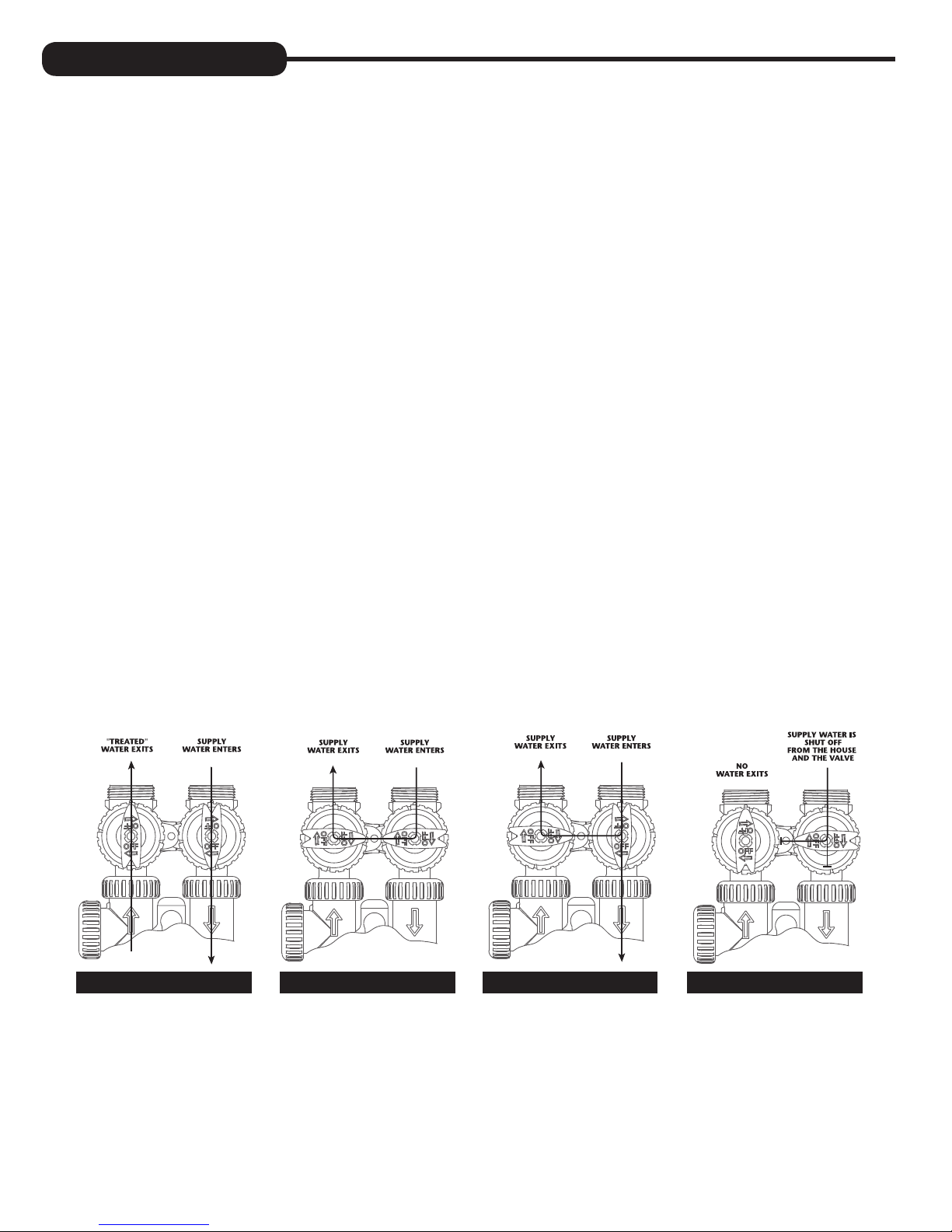
The bypass consists of two interchangeable plug valves that are operated independently by red arrow shaped handles. The
handles identify the direction of flow. The plug valves enable the bypass valve to operate in four positions.
1. NORMAL OPERATION POSITION: The inlet and outlet handles point in the direction of flow indicated by the engraved
arrows on the control valve. Water flows through the control valve for normal operation of a water softener. During
the regeneration cycle this position provides regeneration water to the unit, while also providing untreated water to the
distribution system (Fig. 1).
2. BYPASS POSITION: The inlet and outlet handles point to the center of the bypass. The system is isolated from the water
pressure in the plumbing system. Untreated water is supplied to the building (Fig. 2).
3. DIAGNOSTIC POSITION: The inlet handle points toward the control valve and the outlet handle points to the center of
bypass valve. Untreated supply water is allowed to flow to the system and to the building, while not allowing water to exit
from the system to the building (Fig. 3). This allows the service technician to draw brine and perform other tests without the
test water going to the building.
NOTE: The system must be rinsed before returning the bypass valve to the normal position.
®
and the nuts and caps are glass-filled polypropylene. All seals are self-lubricating
4. SHUT OFF POSITION: The inlet handle points to the center of the bypass valve and the outlet handle points away from
the control valve. The water is shut off to the building. The water treatment system will depressurize upon opening a tap in
the building. A negative pressure in the building combined with the softener being in regeneration could cause a siphoning
of brine into the building. If water is available on the outlet side of the softener, it is an indication of water bypassing the
system (Fig. 4) (i.e. a plumbing cross-connection somewhere in the building).
NORMAL
OPERATION
POSITION
BYPASS POSITION
DIAGNOSTIC
POSITION
SHUT OFF
POSITION
FIGURE 1 FIGURE 3FIGURE 2 FIGURE 4
4
INSTALLATION:
GENERAL INSTALLATION & SERVICE WARNINGS
The control valve, fittings and/or bypass are designed to accommodate minor plumbing misalignments. There is a small
amount of “give” to properly connect the piping, but the water softener is not designed to support the weight of the plumbing.
Do not use Vaseline, oils, other hydrocarbon lubricants or spray silicone anywhere. A silicone lubricant may be used on black
“O” Rings, but is not necessary. Avoid any type of lubricants, including silicone, on red or clear lip seals.
Do not use pipe dope or other sealants on threads. Teflon
brine line connection at the control valve, and on the threads for the drain line connection. Teflon® tape is not used on the nut
connections or caps because “O” Ring seals are used. The nuts and caps are designed to be unscrewed or tightened by hand
or with the special plastic Service Wrench, #CV3193-02. If necessary pliers can be used to unscrew the nut or cap. Do not
use a pipe wrench to tighten nuts or caps. Do not place screwdriver in slots on caps and/or tap with a hammer.
SITE REQUIREMENTS
• water pressure – 25-100 psi • current draw is 0.5 amperes
• water temperature – 33-100°F (0.5-37.7°C) • the plug-in transformer is for dry locations only
• electrical – 115/120V, 60Hz uninterrupted outlet
• the tank should be on a firm level surface
®
tape must be used on the threads of the 1” NPT inlet and outlet, the
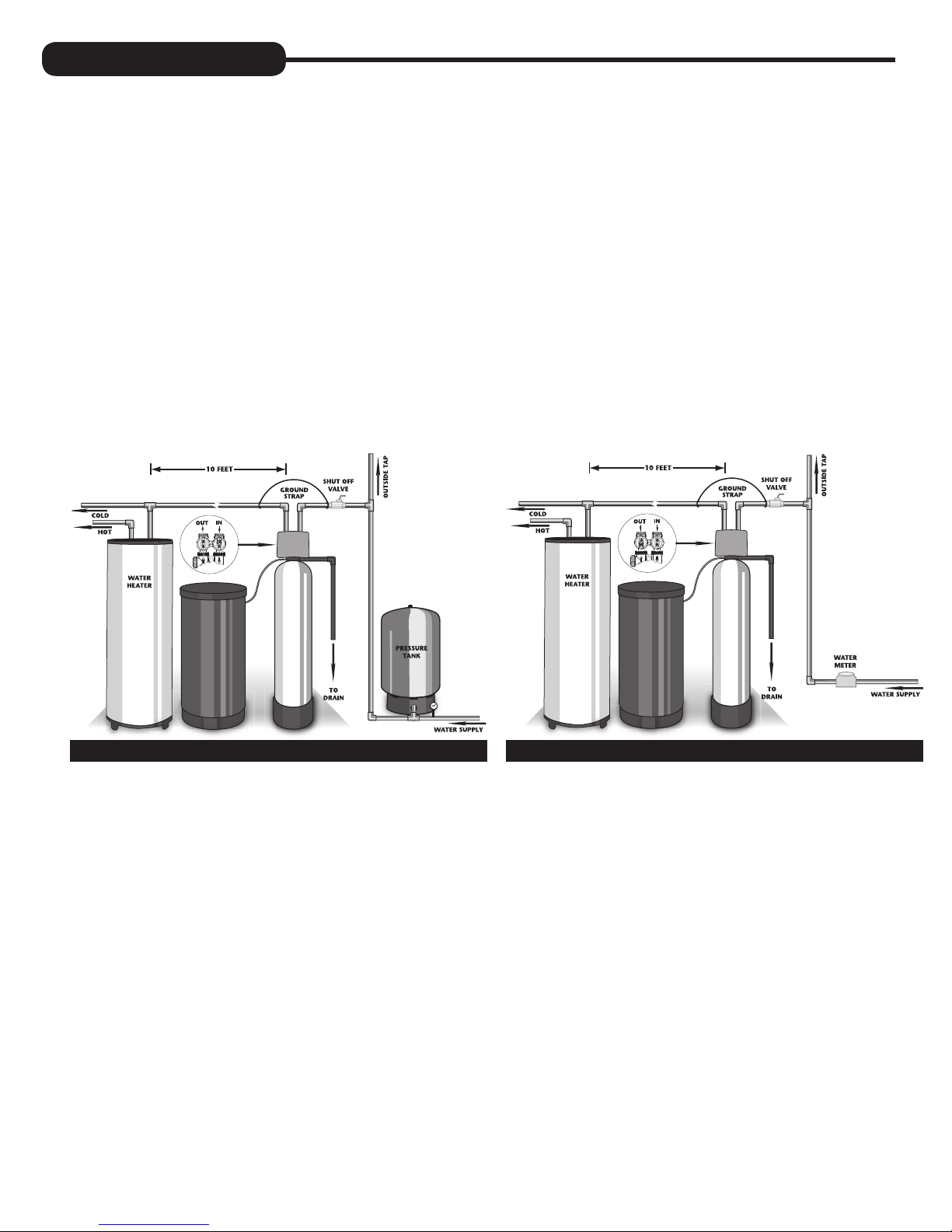
WELL WATER INSTALLATION MUNICIPAL INSTALLATION
1. The distance between the drain and the water conditioner should be as short as possible.
2. Since salt must be periodically added to the brine tank, it should be located where it is easily accessible.
3. Do not install any water conditioner with less than 10 feet of piping between its outlet and the inlet of a water heater.
4. Do not locate unit where it or its connections (including the drain and overflow lines) will ever be subjected to room
temperatures under 33°F.
5. Do not subject the tank to any vacuum, as this may cause an “implosion” and could result in leaking. If there is a possibility
a vacuum could occur, please make provision for a vacuum breaker in the installation.
6. INLET/OUTLET PLUMBING: Be sure to install Bypass Valve onto main control valve before beginning plumbing.
Make provisions to bypass outside hydrant and cold hard water lines at this time. Install an inlet shutoff valve and plumb
to the unit’s bypass valve inlet located at the right rear as you face the unit. There are a variety of installation fittings
available. They are listed under Installation Fitting Assemblies, page 26-27. When assembling the installation fitting
package (inlet and outlet), connect the fitting to the plumbing system first and then attach the nut, split ring and “O” Ring.
Heat from soldering or solvent cements may damage the nut, split ring or “O” Ring. Solder joints should be cool and
solvent cements should be set before installing the nut, split ring and “O” Ring. Avoid getting solder flux, primer, and
solvent cement on any part of the “O” Rings, split rings, bypass valve or control valve. If the building’s electrical system
is grounded to the plumbing, install a copper grounding strap from the inlet to the outlet pipe. Plumbing must be done in
accordance with all applicable local codes.
5
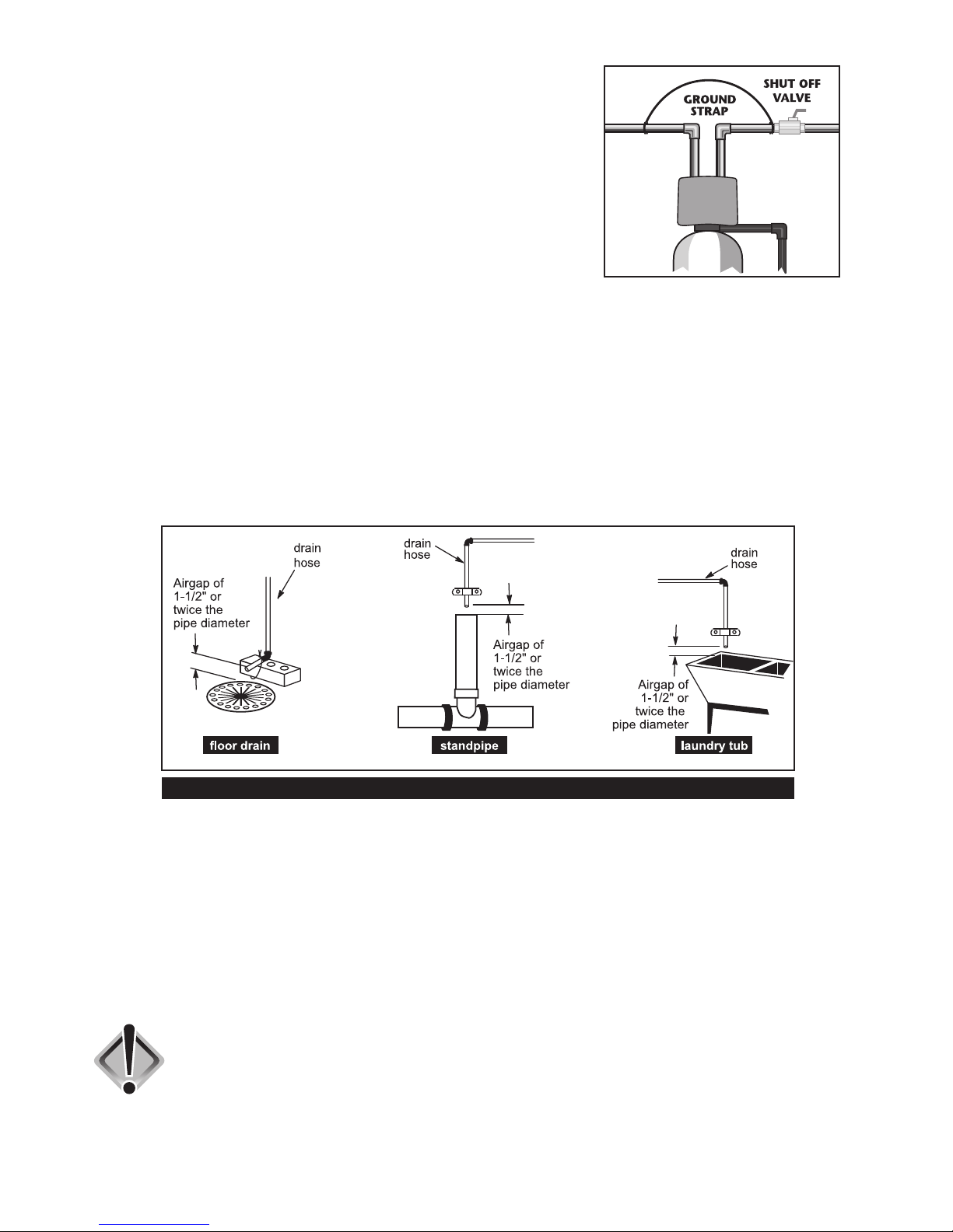
7. INSTALLING GROUND: To maintain an electrical ground in metal plumbing
of a home’s cold water piping (such as a copper plumbing system), install a
ground clamp or jumper wiring.
NOTE: If replacing an existing softener, also replace the ground clamps/wire.
If removing a softener, replace the piping with the same type of piping as the
original to assure plumbing integrity and grounding.
8. DRAIN LINE: First, be sure that the drain can handle the backwash rate of the system. Solder joints near the drain must
be done prior to connecting the drain line flow control fitting. Leave at least 6” between the drain line flow control fitting
and solder joints. Failure to do this could cause interior damage to the flow control. Install a 1/2” I.D. flexible plastic tube
to the Drain Line Assembly or discard the tubing nut and use the 3/4” NPT fitting for rigid pipe (recommended).
If the backwash rate is greater than 7 gpm, use a 3/4” rigid drain line. Where the drain line is elevated
but empties into a drain below the level of the control valve, form a 7” loop at the discharge end of the line so that the
bottom of the loop is level with the drain connection on the control valve. This will provide an adequate anti-siphon trap.
Piping the drain line overhead <10 ft is normally not a problem. Be sure adequate pressure is available (40-60 psi is
recommended). Where the drain empties into an overhead sewer line, a sink-type trap must be used. Run drain tube to its
discharge point in accordance with plumbing codes. Pay special attention to codes for air gaps and anti-siphon devices.
NOTE: Drain line nut will not be supplied for units having a backwash rate greater than 7 gpm.
TYPICAL DRAIN LINE INSTALLATIONS
9. BRINE TANK CONNECTION: Install the 3/8” O.D. polyethylene tube from the Refill Elbow to the Brine Valve in the
brine tank.
10. OVERFLOW LINE CONNECTION: An overflow drain line is recommended where a brine overflow could damage
furnishings or the building structure. Your softener is equipped with a brine tank safety float which greatly reduces
the chance of an accidental brine overflow. In the event of a malfunction, however, an overflow line connection will
direct the “overflow” to the drain instead of spilling on the floor where it could cause considerable damage. This
fitting is an elbow on the side of the brine tank. Attach a length of 1/2” I.D. tubing to fitting and run to drain. Do not
elevate overflow line higher than 3” below bottom of overflow fitting. Do not “tie” this tube into the drain line of the
control valve. Overflow line must be a direct, separate line from overflow fitting to drain, sewer, or tub. Allow an air
gap as per the drain line instructions.
CAUTION: Never insert a drain line into a drain, sewer line, or trap. Always allow
an air gap between the drain line and the wastewater to prevent the
possibility of sewage being back-siphoned into the conditioner.
6
PROGRAMMING PROCEDURES:
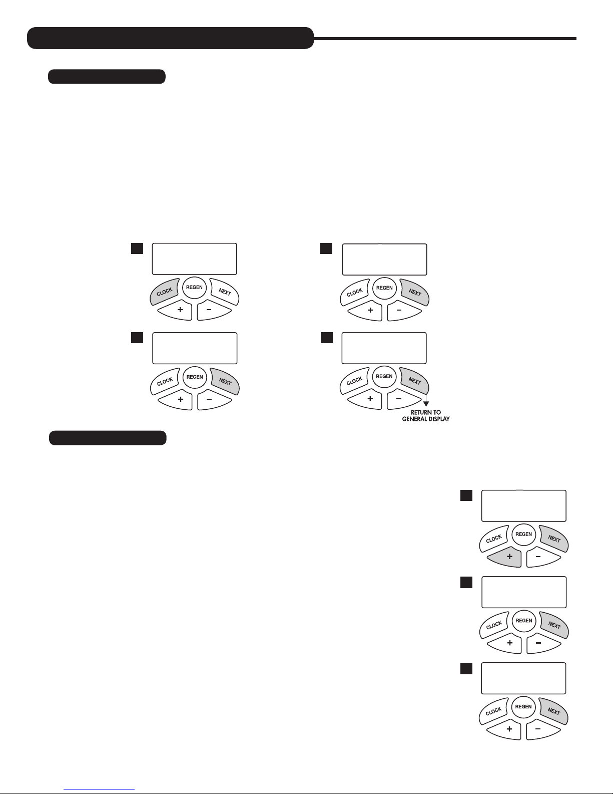
1. Set time of day:
Time of day should only need to be set after extended power outages or when daylight saving time begins or ends. If an
extended power outage occurs, the time of day will flash on and off indicating that the time should be reset.
STEP 1 – Press
STEP 2 – CURRENT TIME (HOUR): Set the hour of the day using + or — buttons. AM/PM toggles after 12.
STEP 3 – CURRENT TIME (MINUTES): Set the minutes using + or — buttons. If it is desired to back up to the
STEP 4 – CURRENT DAY: Set the day of the week using + or — buttons. Pressing
SET CLOCK.
Press
NEXT to go to step 3.
previous step press
return to the general operating display (page 9).
1
TIME MINUTES
3
SET
REGEN button once. Press NEXT to go to step 4.
2
4
2:10
AM
TIME HOUR
SET
CURRENT DAY
SET
2:00
MON
NEXT will exit SET CLOCK and
AM
2. Programming:
NOTE: The manufacturer has preset the unit so that the gallons between regenerations will be automatically calculated
after the hardness is entered.
STEP 1 – Press
STEP 2 – HARDNESS: Set the amount of hardness in grains per gallon (default 20)
NOTE: If a resin media is used in the softener, increase the grains per
Press
Press
STEP 3 – DAYS BETWEEN REGENERATION (DAY OVERRIDE): The manufacturer
Set Day Override using + or — buttons (6 is recommended):
• set number of days between regeneration (1 to 28); or
• set to “OFF”
NEXT and + simultaneously for 3 seconds.
using the + or — buttons. The allowable range is from 1 to 150 in 1 grain
increments.
gallon if soluble iron is present (1 ppm = 4 gpg). This display will show
“–nA– (not available)” if “FILTER” is selected or if “AUTO” is not factory set.
NEXT to go to step 3.
REGEN if you want to exit.
has factory set 6 DAYS as the default. This is the maximum number of days
between regenerations. If this is set to “OFF”, regeneration initiation is based
solely on gallons used. If any number is set (allowable range from 1 to 28), a
regeneration initiation will be called for on that day even if a sufficient number
of gallons were not used to call for a regeneration.
1
WATER HARDNESS
2
SET
DAYS BETWEEN REGEN
3
SET
20
GR
6
7
NOTE: This valve has the capability of regenerating up to six times in one day.
This can be observed by pressing the
CLOCK and + buttons simultaneously, then
using + or — buttons to toggle the correct number of regenerations per day
as desired (see example to right). Press
NEXT to set the times per day or select
“OFF” to return to Days Between Regen. These settings are typically used in
commercial settings.
Press
NEXT to go to step 4. Press REGEN to return to the previous step.
STEP 4 – REGENERATION HOUR: The manufacturer has factory set 2:00 A.M. as
the default. This is the hour of day for regeneration and can be reset by using
+ or — buttons. “AM/PM” toggles after 12. The default time is 2:00 a.m.
(recommended for a normal household).
Press
NEXT to go to step 5. Press REGEN to return to the previous step.
REGENS PER DAY
SET
Example: Indicates unit set
to regen 4 times in one day.
REGEN TIME HOUR
4
SET
4 PER
2:00
AM
STEP 5 – REGENERATION MINUTES: Set the minutes using + or — buttons. Press
NEXT to go to step 6. Press REGEN to return to previous step. To initiate an
immediate manual regeneration, press and hold the
REGEN button for three
seconds. The system will begin to regenerate immediately. The control may
be manually stepped through the regeneration cycles by pressing REGEN.
Press
NEXT to go to step 6. Press REGEN to return to the previous step.
STEP 6 – SERVICE ALARM GALLONS: The manufacturer has factory set “OFF”
as the default. This feature is used to signal service into the future. This
is typically set by the installing dealer to warn homeowner that service is
required after a preset number of gallons have been consumed. If the
feature is active, a specific gallon amount will appear.
Press
NEXT three times to advance past this screen.
STEP 7 – SERVICE ALARM TIME: The manufacturer has factory set “OFF” as the
default. This feature is used to signal service into the future. This is typically
set by the installing dealer to warn homeowner that service is required after a
period of time has passed. If the feature is active, a specific number of days
will appear.
Press
NEXT three times to advance past this screen.
STEP 8 – ALARM BUZZER: The manufacturer has factory set “ON” as the default. An
alarm will sound (at the indicated time) after a regeneration, if there is no salt
or if another error has occurred. Turn the alarm “OFF” or “ON” using the + or
— buttons. Press
NEXT.
NOTE: This feature allows you to program the time in which the alarm
buzzer will sound, permitting the installer to pick a time when the owner will
be home or awake to hear it.
Setting Alarm Buzzer Start Time: Press + or — button to select the correct
hour the buzzer is to start sounding. Be sure to also set AM or PM as necessary.
(Default is set to 6:00 a.m.) Press
NEXT.
Setting Alarm Buzzer End Time: Press + or — button to select the
correct hour the buzzer is to stop sounding in the day. Be sure to also set
AM or PM as necessary. (Default is set to 10:00 p.m.) Press
NEXT.
REGEN TIME MINUTES
5
SET
SERVICE ALARM GAL
6
SET
SERVICE ALARM TIME
7
SET
ALARM BUZZER START
8
SET
ALARM BUZZER END
SET
2:00
OFF
OFF
6:00
10:00
AM
AM
PM
STEP 9 – DISPLAY BACKLIGHT: The manufacturer has factory set “ON” as the
default. Turn the light “OFF” or “ON” using the + or — buttons. “OFF”
will turn display backlight off after five minutes of keypad inactivity.
Press
NEXT to exit installer programming.
8
LIGHT NORMALLY
9
SET
ON
OPERATING DISPLAYS AND INSTRUCTIONS:
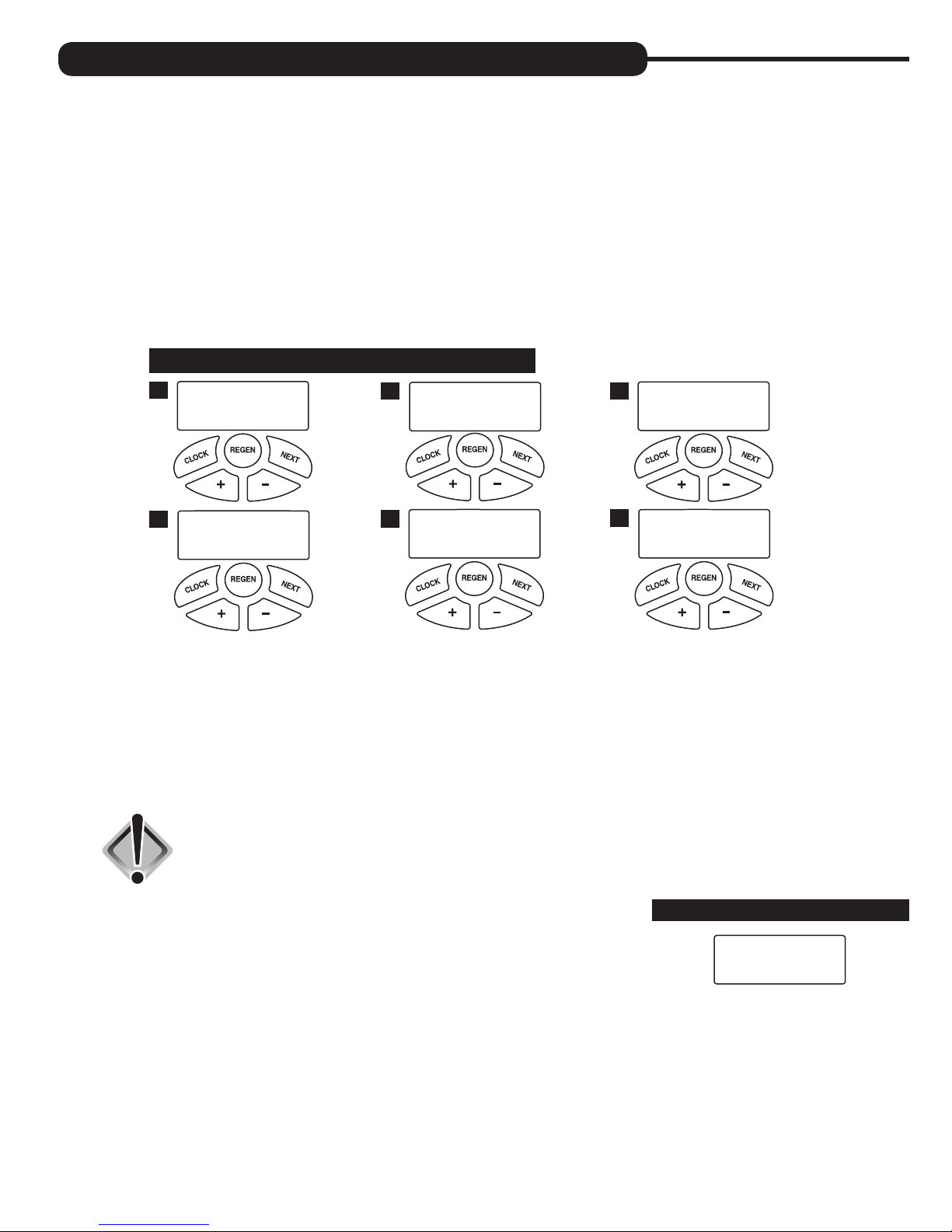
1. GENERAL OPERATION: When the system is operating, one of five displays may be shown and will alternate with the
installing dealer’s name and phone number for future service. Pressing NEXT will alternate between the displays.
1. CURRENT TIME OF DAY and GPM
2. FLOW RATE which is the current treated water flow rate through the system in Gallons Per Minute
3. VACATION MODE allows the system to be “shut down” when there will be no water usage for an extended
period of time
4. CAPACITY REMAINING which is the gallons that will be treated before the system signals a regeneration cycle
5. DAYS TO A REGEN is the number of days left before the system goes through a regeneration cycle, based on
the days override value
6. DEALER NAME AND PHONE NUMBER is the dealer information to call when service is needed (this screen will
only appear if set by dealer)
The user can scroll between the displays as desired.
TIME OF DAY MON
1
GPM
FLOW RATE
2
2:408
PM
8.0
GPM
CAPACITY REMAINING
3
GPM GAL
1600
8
DAYS TO A REGEN
4
GPM
8
If the system has called for a regeneration that will occur at the preset time of regeneration, the words “REGEN
TODAY” will appear on the display.
If a water meter is installed, “GPM” flashes on the display when water is being treated, indicating gallons per
minute going through the system.
2. VACATION MODE: This feature may be used to “shut down” the system while on vacation. The manufacturer has
factory set “OFF” as the default. Turn feature “OFF” or “ON” using the + or — buttons. When turned “ON”, the
unit will not regenerate while there is no water usage. Once water usage is observed (minimum of 50 gallons), the
unit will automatically regenerate that night and resume normal operation.
CAUTION: Depending on the severity of water conditions and the length of no water
3. REGENERATION MODE: Typically a system is set to regenerate at a time of no
water usage. If there is a demand for water when the system is regenerating, untreated
water will be delivered. When the system begins to regenerate, the display will include
information about the step of the regeneration process and the time remaining for that
step to be completed. The system runs through the steps automatically and will reset
itself to provide treated water when the regeneration has been completed.
3
usage, it may not be recommended to use this feature. Please contact
dealer or manufacturer for more information.
ON VACATION
5
NO
PHONE NUMBER
6
DEALER NA
REGENERATION MODE
BACKWASH
8:22
4. MANUAL REGENERATION: Sometimes there is a need to regenerate before the control valve calls for it. This
may be needed if a period of heavy water use is anticipated or when the system has been operated without salt.
• To initiate a manual regeneration at the next preset regeneration time, press and release
words “REGEN TODAY” will flash on the display to indicate that the system will regenerate at the next
regeneration time (set in Programming, steps 4 and 5). If you pressed the
button again will cancel the command.
• To initiate a manual regeneration immediately, press and hold the
system will begin to regenerate immediately. This command cannot be cancelled.
REGEN. The
REGEN button in error, pressing the
REGEN button for three seconds. The
9
Once a manual regeneration is initiated, the unit will go into the FILL position.
This position allows water to enter the brine tank until it reaches the proper
level. Once this position is complete, you will notice a 240 Minute (4 hours)
SOFTENING position. This 4-hour window allows the salt to dissolve and
achieve proper brine strength. During these FILL and SOFTENING positions,
you will have softened water available for use. Once the unit advances to
the BACKWASH position and subsequent positions thereafter (see Start Up
Instructions for regeneration sequence), the water softener will deliver water,
but it will be untreated.
IMPORTANT: With the Dry Salt Storage Feature, the brine tank will refill 4
hours before the actual regeneration occurs. You may experience a small amount
of noise for a short period of time at 10:00 p.m. (with typical setting) on the night
that regeneration is to occur. This noise is only the brine tank filling and at no
time during this process will you be without treated water.
MANUAL REGENERATION
REGEN TODAY and TIME OF DAY
will flash alternately if a regeneration
is expected tonight.
REGEN TODAY MON
GPM
2:408
PM
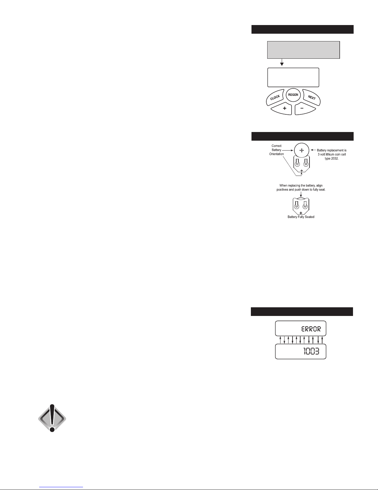
5. POWER LOSS AND BATTERY REPLACEMENT: The transformer comes with a
15 foot power cord and is designed for use with the control valve; the transformer
BATTERY REPLACEMENT
should only be used in a dry location.
In the event of a power outage, the control valve will remember all settings and
time of day. If an extended power outage occurs, the control valve will keep time
of day until the battery is depleted. When the battery becomes depleted, the only
item that needs to be reset is the time of day and will be indicated by the time of
day flashing. All other settings are permanently stored in the nonvolatile memory.
If a power loss occurs and the time of day flashes, this indicates that the battery
is depleted. The time of day should be reset and the non-rechargeable battery
should be replaced. The battery is a 3 Volt Lithium Coin Cell type 2032 and is
readily available at most stores. To access battery location, remove front cover
(see diagram on page 18 for battery location).
6. CHECK SALT INDICATOR AND AUDIBLE ALARM: This control valve (not available on CSP, CSPRC and CSPC
models) is equipped with a Low Salt Warning to alert homeowners that the system is operating in a low salt condition.
This usually indicates that the salt level in the brine tank is too low to operate properly. If “CHECK SALT” appears, there
will usually be an audible alarm that sounds also (if turned on), alerting you to these conditions.
To turn off alarm: If the audible alarm sounds due to a low salt condition, press any button on the face of the
control valve to turn off. If salt is not added to the brine tank before the next regeneration,
the CHECK SALT indicator will alarm again.
IMPORTANT: If you feel that the salt level is adequate (at least 1/3 full) in the brine tank, please contact the dealer
that installed your system for service.
7. ERROR MESSAGE: If the word “ERROR” appears and flashes alternately with
ERROR
the dealer name and phone number, record the ERROR number and your contact
servicing dealer promptly. This indicates that the control valve was not able to
function properly.
8. BRINE TANK MAINTENANCE AND SALT: Refill the brine tank as necessary,
making sure at least 1/3 of the brine tank is full at all times. Without proper salt
levels, the water softener may not operate properly.
Because “typical” settings of this water softener include a dry salt storage feature (no water in brine tank between
regeneration), the manufacturer recommends the use of solar salt for best results. The brine tank is manufactured for
the use of solar, pellets or rock salt. Do not use block salt. If pellet or rock salt is used, a cleaning of the brine
tank every six months is recommended. If the dry salt storage feature is not being utilized, block salt may be used.
CAUTION: With some models the manufacturer does NOT recommend the use of
any resin cleaners, nor placing any resin cleaners into the brine tank.
Furthermore, do not use any salt that indicates it is an iron cleaning salt
or that contains any cleaning additives. This may be harmful to the water
softener and for human consumption. Consult dealer for proper cleaning
instructions and agents.
10
 Loading...