

Water2Buy RO 3.2 User Manual
3002-R15.3.2

2
Safety & Care Advice
You must turn off mains water to your home before installing the reverse osmosis system.
Water2buy™ installation policy: All installation shall be performed in a neat, professional
manner in accordance with generally accepted trade practices. Further, all installations shall
comply with all local laws, codes, regulations, and ordinances.
Read all steps, guides and rules carefully before installing and using your reverse osmosis
unit. Follow all steps exactly to correctly install. Reading this manual will help you get all the
benefits from your reverse osmosis unit.
Do not attempt to use this product to make safe drinking water from non-potable water
sources. Do not use the unit on microbiologically unsafe water, or water of unknown quality.
Check with your local water department for plumbing and sanitation codes. You must respect
their instructions and codes while installing the unit. This guide is a suggested install method;
follow your local codes if they differ from the instructions given in this manual.
The non-pumped reverse osmosis unit works on water pressures of minimum 1.7bar (25 psi)
to maximum 6 bar (90 psi). If your house water pressure is over the maximum, install a
pressure-reducing valve in the water supply pipe to the reverse osmosis unit.
The pumped reverse osmosis unit works on water pressure of minimum 1bar (15psi) to
maximum 6 bar (90 psi). If your house water pressure is over the maximum, install a
pressure-reducing valve in the water supply pipe to the reverse osmosis unit.
Do not install the reverse osmosis unit outside, or in extreme hot or cold temperatures.
Temperatures of the water supply to the reverse osmosis unit must be between 5c and 40c.
Do not install on hot water supplies.
The reverse osmosis membrane comes in an airtight sealed bag for storage and shipment, do
not use if seal is broken.
Caution: chlorine in the water will destroy the reverse osmosis
membrane. Most cities add chlorine to the water supply to kill bacteria.
The pre-filter removes chlorine before it enters the reverse osmosis
membrane. It is important to replace the filter cartridges at least every 12
months.
Where to install your reverse osmosis unit
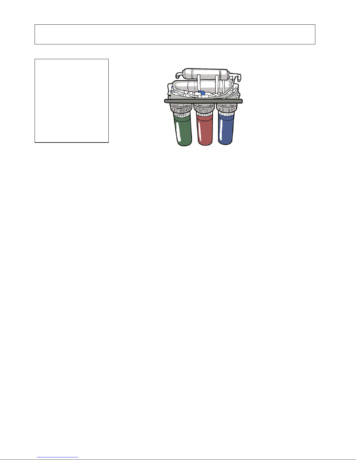
The reverse osmosis assembly and storage tank is designed for installations under the sink,
usually in the kitchen. The reverse osmosis assembly mounts on a wall surface, or can sit on
the cabinet floor next to the storage tank. The reverse osmosis product water tap installs on
the sink, or on the countertop next to the sink.
Tubing lengths should allow for the removal of the assembly from the hanger washers for
servicing. If tubing lengths are shortened for neater appearance, it may be necessary to keep
the assembly on the hanger washers for service.
You can also locate the reverse osmosis assembly and storage tank in any remote location
from the tap, observing safety guides in this manual. You do need a nearby water source and
drain point.
3
Installing your reverse osmosis unit
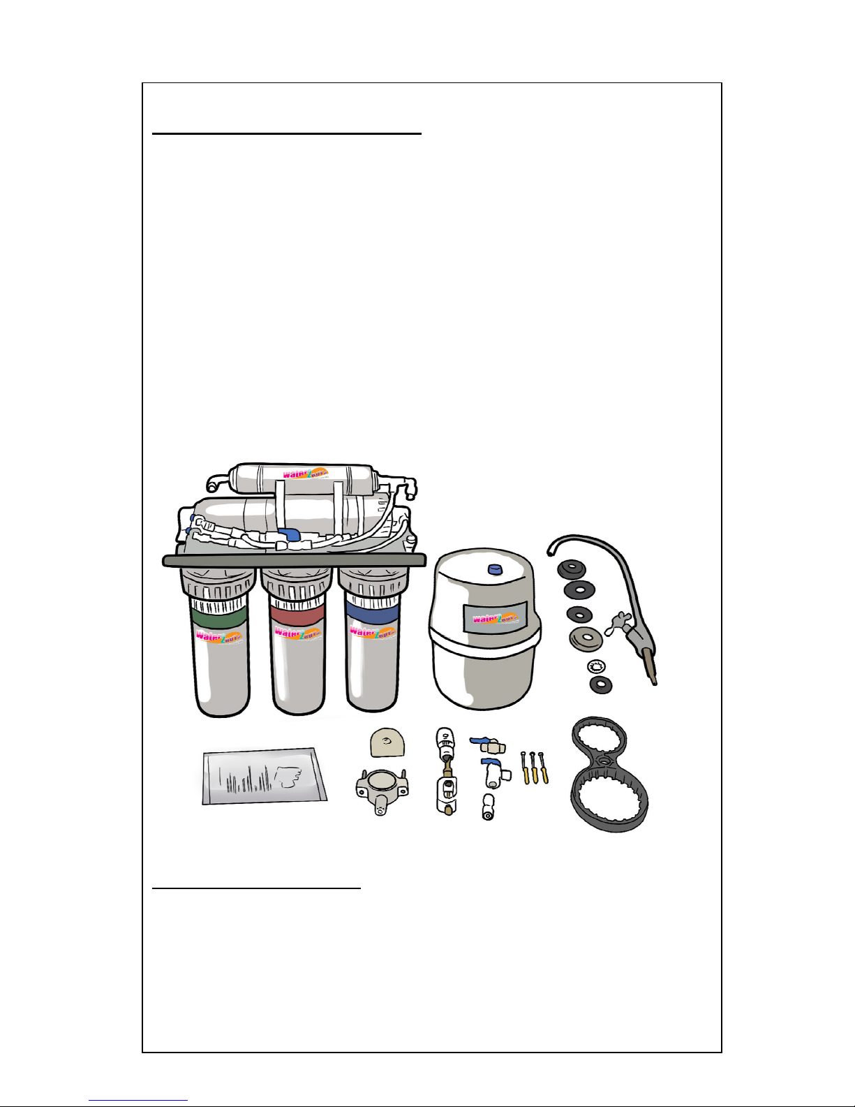
Check parts included: unpack the box and remove the reverse osmosis unit. In addition to the
assembled reverse osmosis and the storage tank, the unit includes the parts listed below:
•
Reverse osmosis unit
•
Storage tank
•
Tap, washers and quick connect fitting.
•
Manual
•
Waster clamp
•
Saddle valve
•
Inlet water connector and valve
•
Bracket (Used where you want to mount the tap directly onto the unit)
•
Tank valve
•
Housing Spanner
•
Mounting screws
•
Tubing
•
Power supply (RO 600, RO 650 & RO 700 models only)
•
Mineral Filter (RO 550 & RO 650 models only)
•
UV Filter (RO 700 model only)
Tools and materials needed
•
Adjustable wrench / Plumbing wrench
•
Pliers
•
Pipe wrench to fit sink drain
•
Screwdriver
•
Teflon tape or Pipe joint compound (thread seal, approved for use on potable water
supplies
•
Drill with 3mm, 5mm and 12mm bits.
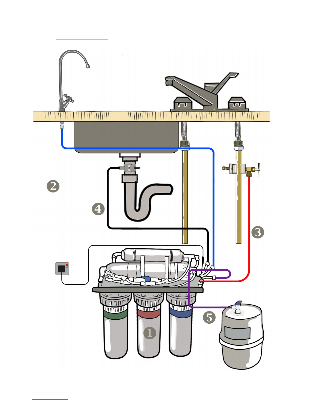
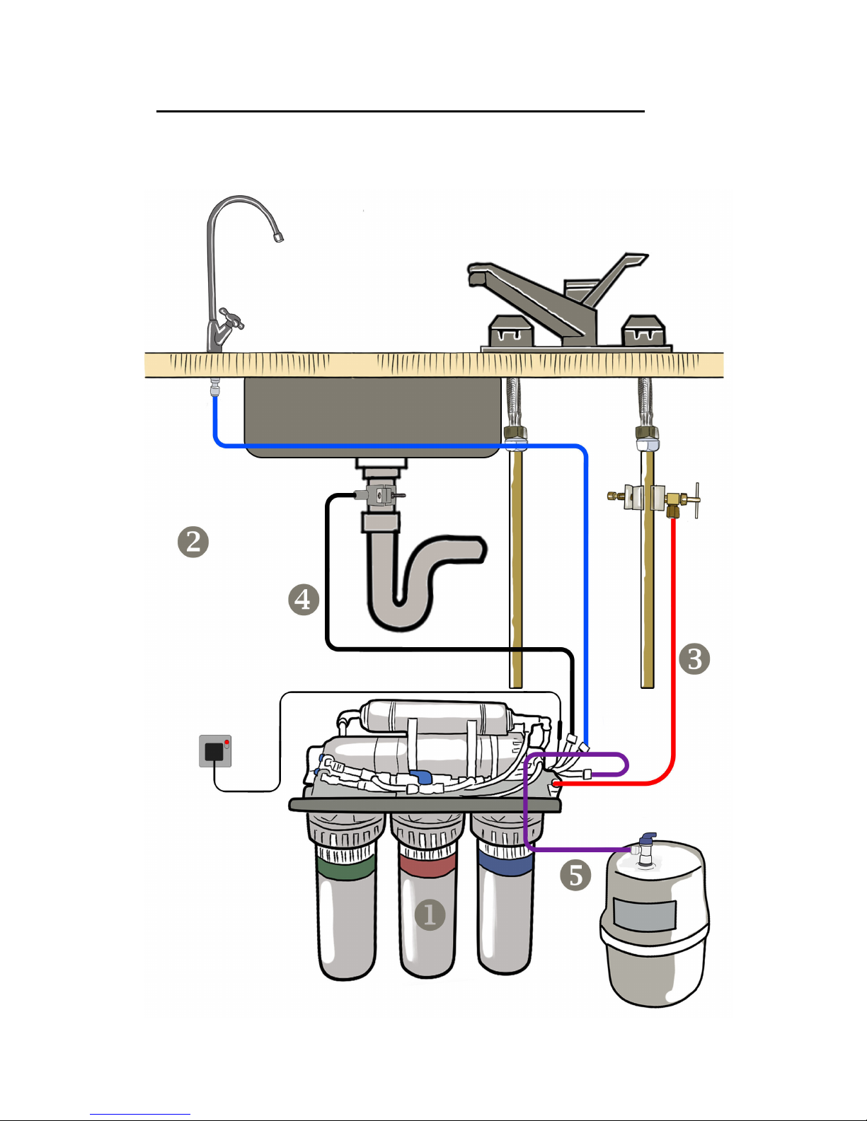
Reference Diagram
A
ssembly Instructions:
5
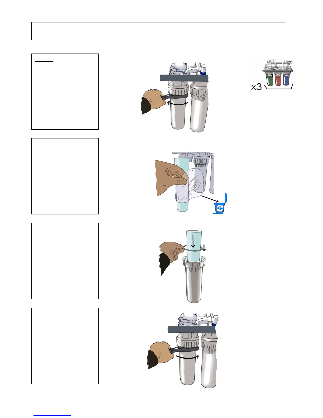
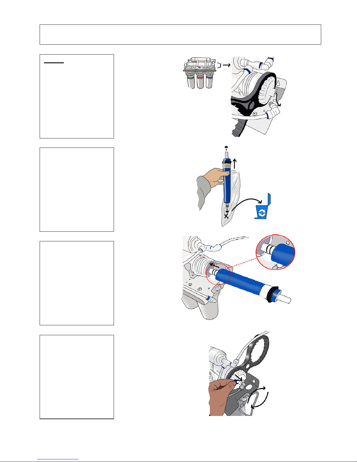
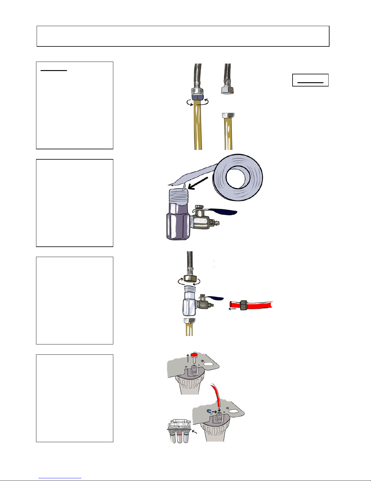
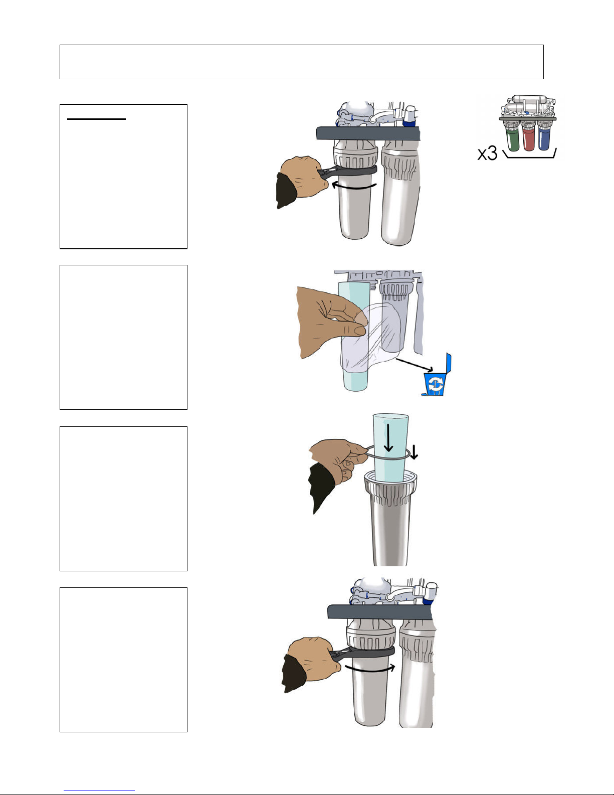
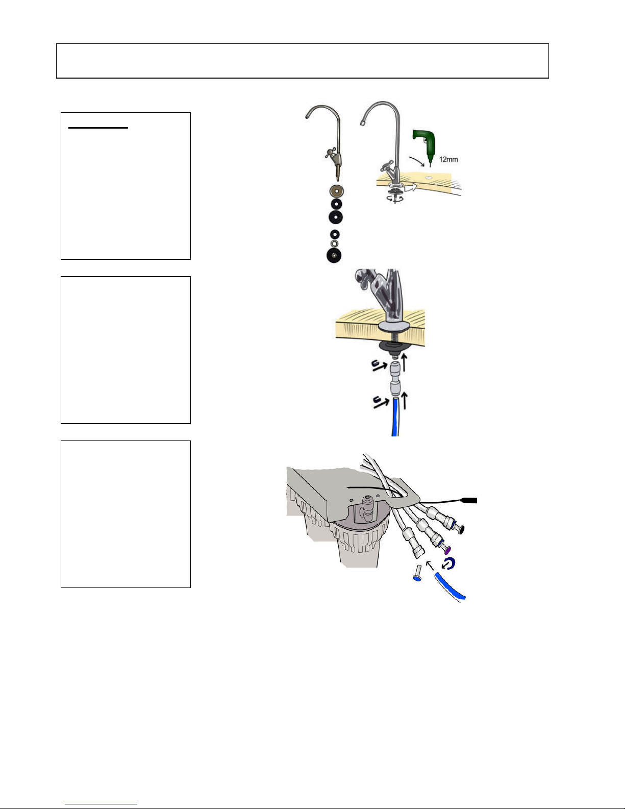
Step 1
A:
Unscrew the 3 filter
housings using the
spanner provided.
B:
Remove the filters from
the packaging.
Place the filters inside their
housings.
C:
Place the o-ring rubber
seal on top of the housing.
Hand screw the housing
back onto the reverse
osmosis unit.
D:
Tighten the filter
housings with the spanner.
A
ssembly Instructions:
6
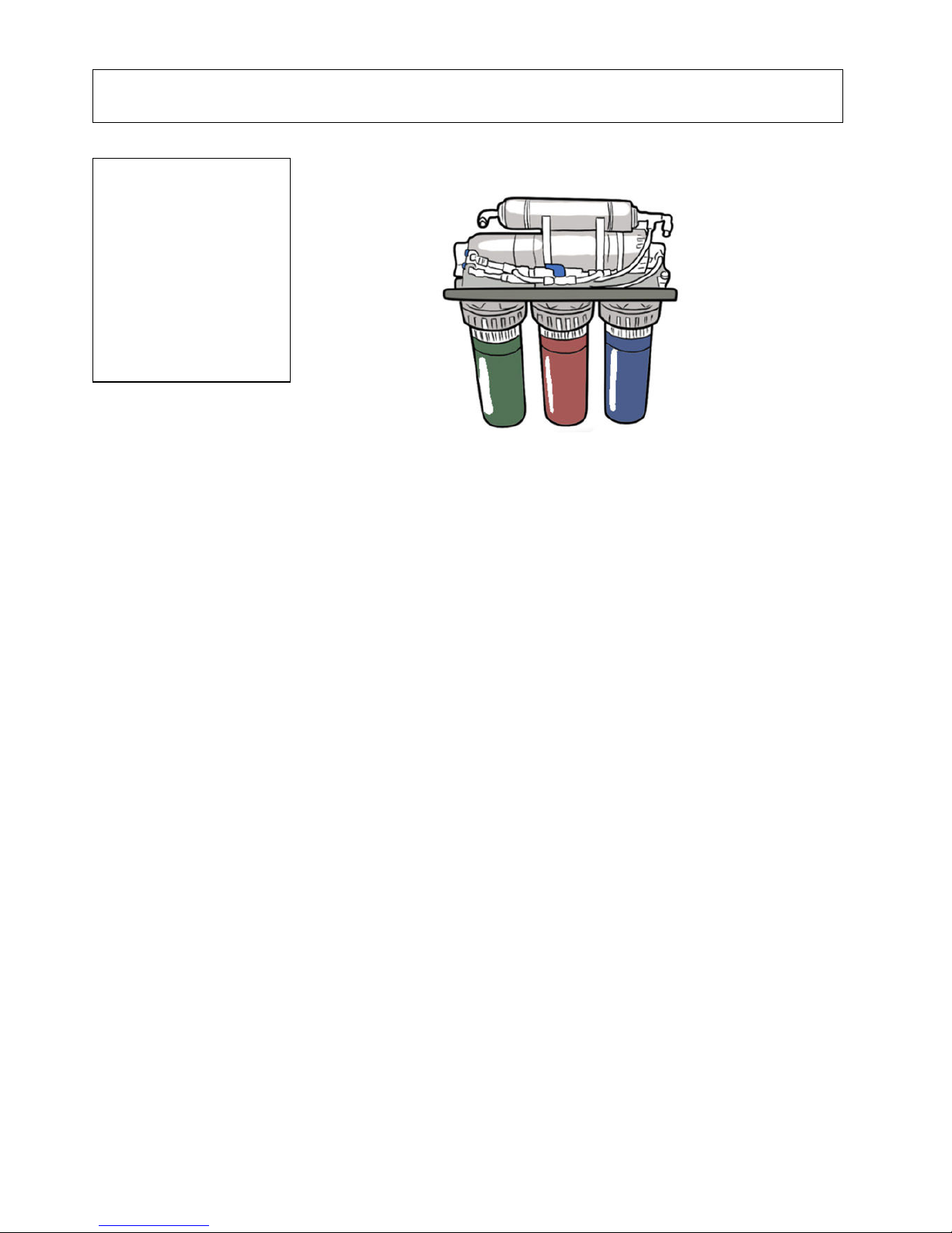
E:
Make sure the correct
filters are used in the
correct housing.
Water2Buy filters are
colour-coded. From
RIGHT to LEFT:
PP (Blue label filter)
GAC (Red label filter)
CTO (Green label filter)
7
A
ssembly Instructions:
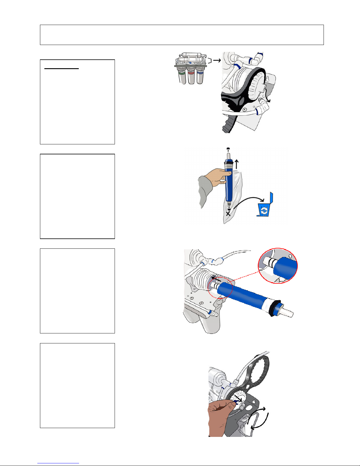
Step 2
A:
Disconnect the tubing
from the membrane
housing for access.
Unscrew the cap using the
spanner provided.
B:
Remove the
membrane form the
packaging.
Remove any black plugs
from the ends of the
membrane if present.
C:
Insert the membrane in
the correct way as shown.
D:
Replace the housing
cap and tighten with the
spanner.
Replace the tubing.
8
A
ssembly Instructions:
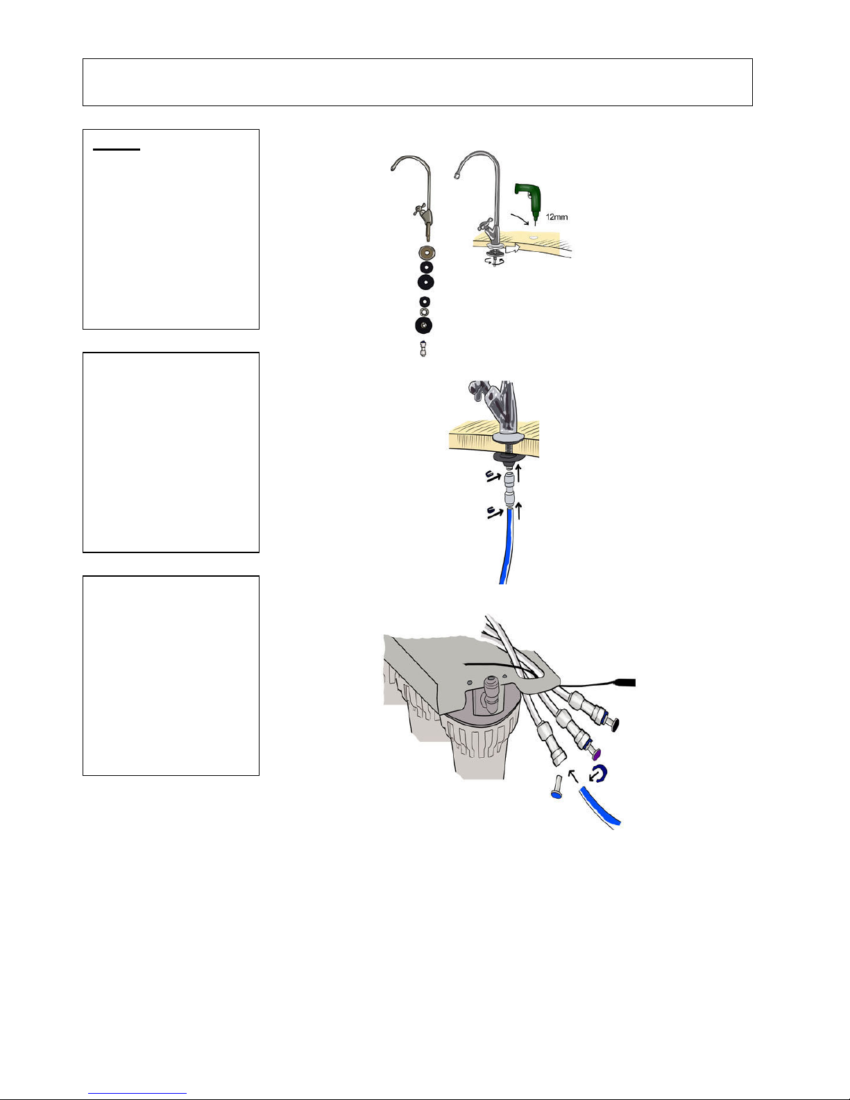
Step 3
A:
Bore a 12mm hole in
kitchen sink or worktop for
mounting the tap. Secure
the tap to the sink using
the washers as shown.
B:
Push the quick connect
fitting onto the base of the
tap.
C:
Connect the
tubing
form
the inline filter to the
tap as shown with the blue
tubing (2) on the reference
diagram.
9
A
ssembly Instructions:
You can use Step 4.1 or 4.2. Do not use both!
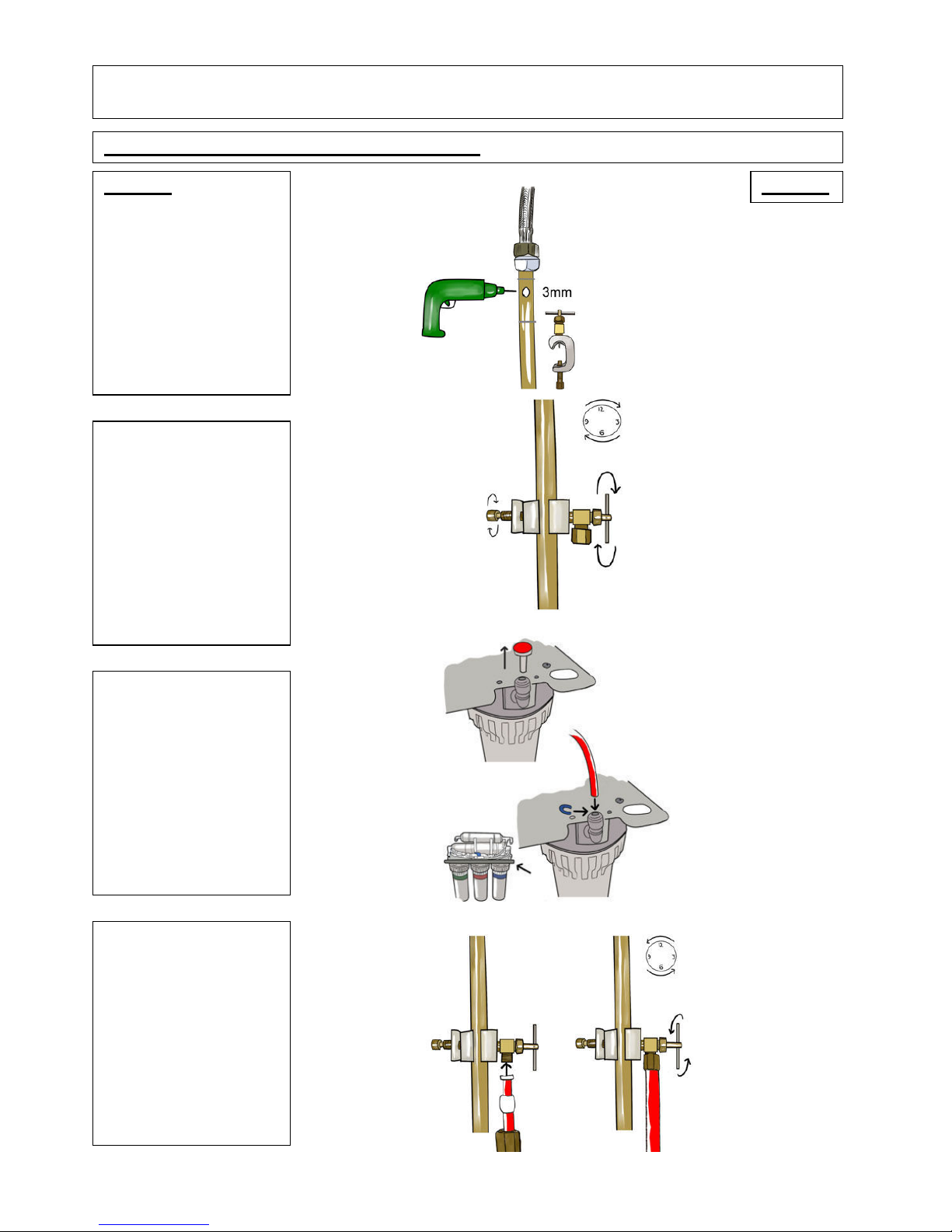
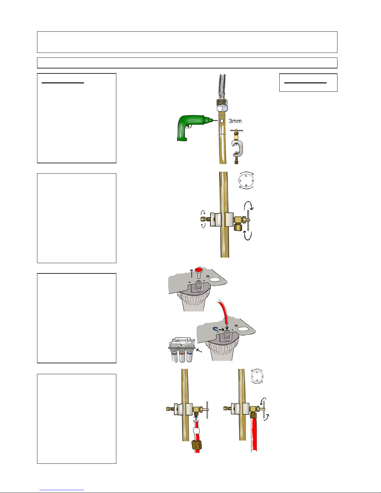
Step 4.1
Step 4.1
A:
Locate the mains water
pipe under kitchen sink.
Make sure you have
turned off the main water
supply to your house.
B:
Attach the saddle
valve to the water mains
copper pipe, if installing
the saddle valve on plastic
pipe you must bore a 3mm
hole first or the unit may
stop working.
C:
Use the plastic insert
and plastic olive on the
tubing. Connect the tubing
from saddle valve to the
first filter as shown with
red tubing (3) on the
reference diagram.
D:
Turn the saddle valve
clockwise to pierce hole in
pipe then open fully (turn
anti-clockwise). If only half
opened it may leak. If it
leaks, then tighten the nut
on the saddle valve.
A
ssembly Instructions:
10
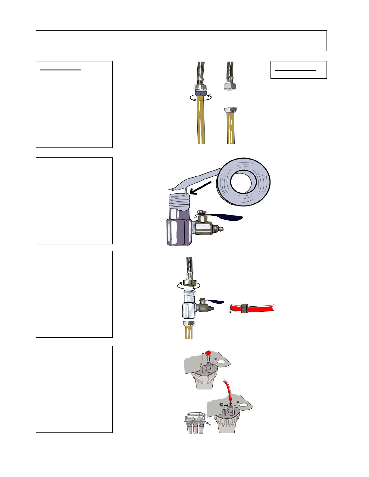
Step 4.1
A:
Unscrew the cold tap
from the mains water pipe
at the joint.
B:
Coat the inlet water
connector and the valve
with Teflon tape.
C:
Insert the inlet water
connector between the tap
and the mains water joint.
Tighten watertight. Screw
the valve into the inlet
water connector.
D:
Connect the tubing
from valve to the first filter
as shown with red tubing
(3) on the reference
diagram.
Step 4.2
11
A
ssembly Instructions:
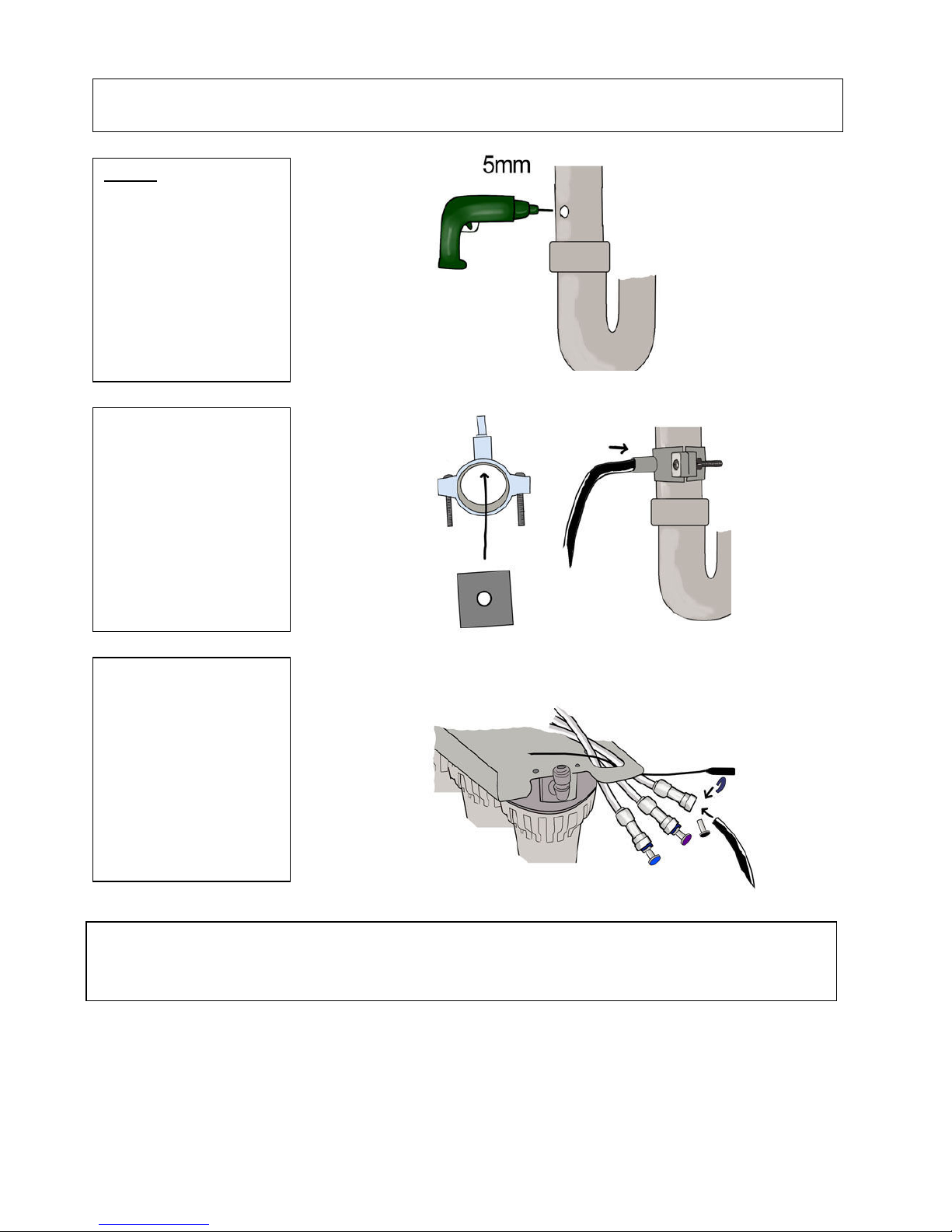
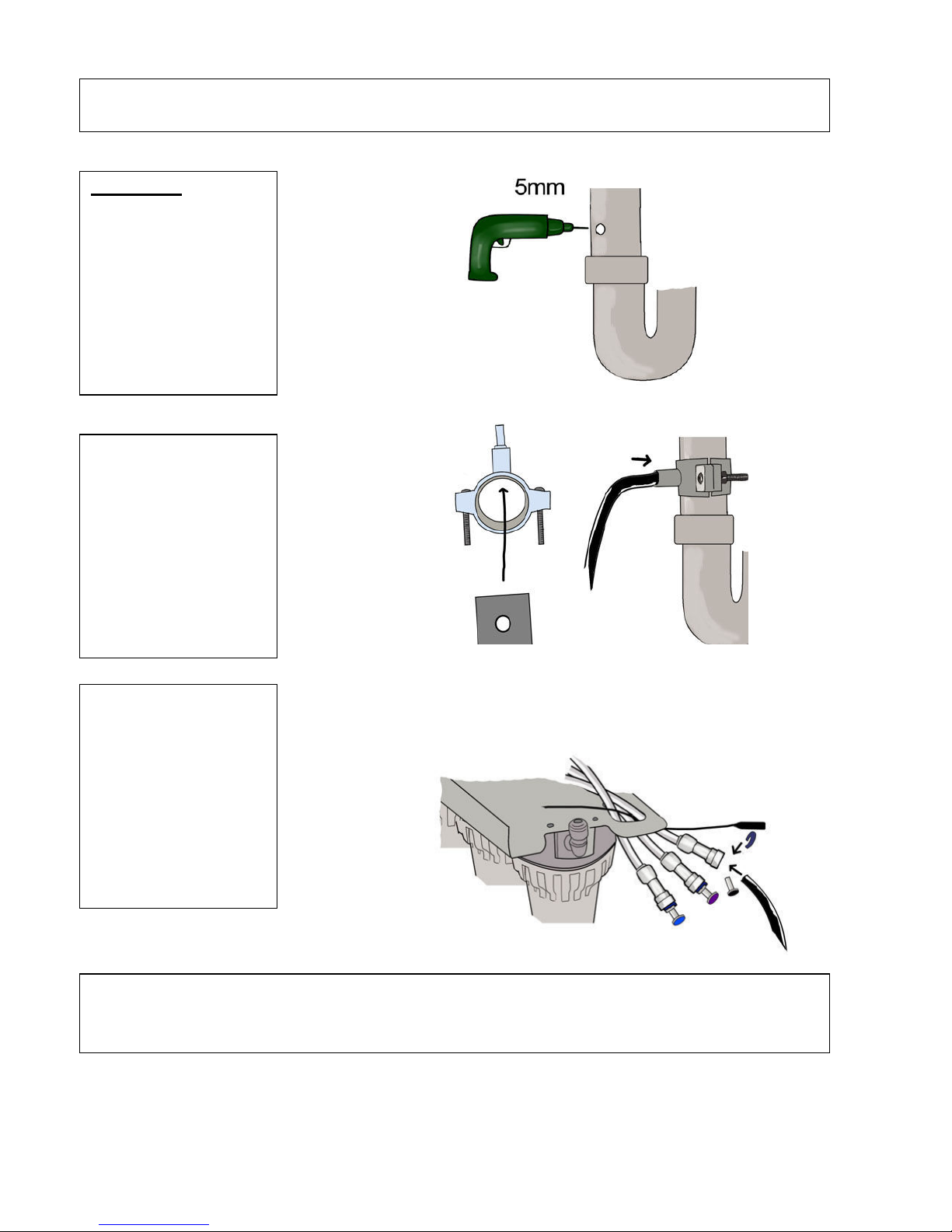
Step 5
A:
Bore a 5mm hole in
waste pipe above the trap
and attach the waste
clamp.
B:
Make sure the seal
washer is used.
C:
Connect waste tubing
from the reverse osmosis
unit to waste clamp as
shown with the black
tubing (4) on the diagram.
Important:
It’s recommended that you sanitize the storage tank before use. To do this, add 1-2 drops of
disinfectant to the storage tank (Use water2buy™ sanitizer, Milton™ or any other disinfected that’s safe for use
with drinking water).
12
A
ssembly Instructions:
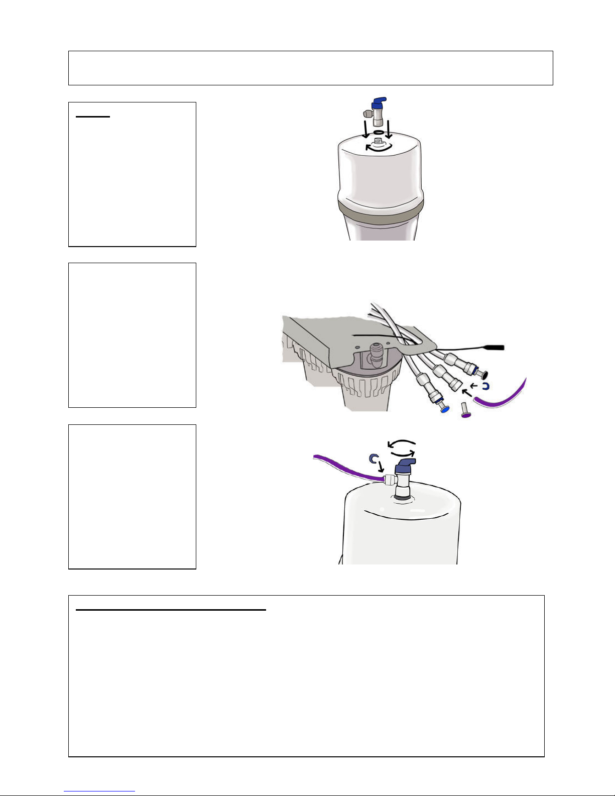
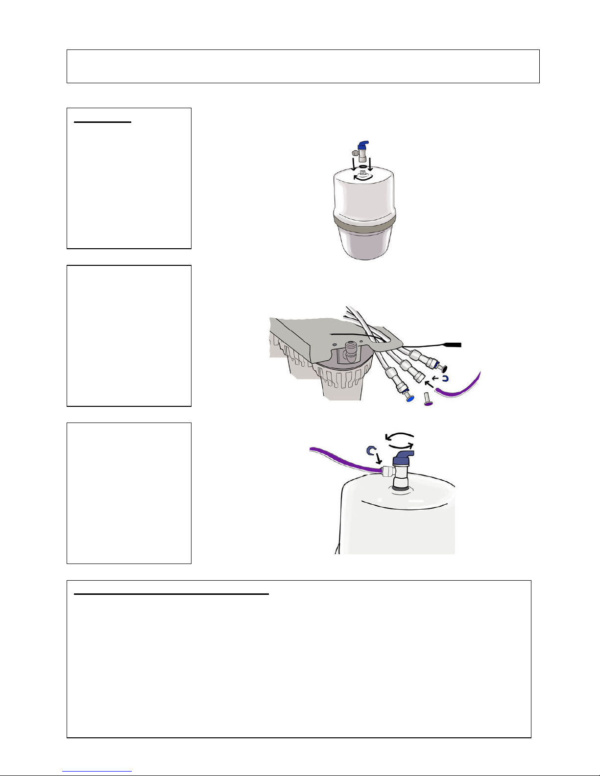
Step 6
A:
Screw the valve onto
the top of reverse osmosis
tank. Make sure you put
on the washer to seal the
connection.
B:
Connect the tank to the
filter as shown with the
purple tubing (5) on the
reference diagram.
C:
Open the valve on the
top of the tank.
Perform post install system checks
Turn on the mains water.
Check for leaks at all joints and connections.
Wait until the entire system is pressurised.
Leave for three hours.
Check for leaks at all joints and connections again.
Turn on water tap until water stops and pressure tank is empty.
It is normal for some black carbon fines to appear in the water when emptying the first two tanks of water.
The first two tanks of water should not be used.
After two hours, re-check for leaks and then the system is good to use.
For more help please watch the installation video on website www.water2buy.com
13
Care of your reverse osmosis unit
At least every 12 months, replace the 3 pre-filters (12) and 1 post-filter cartridge (2). Available on www.water2buy.com
product code YEAC7, yearly filter replacement set.
Replace the reverse osmosis membrane cartridge (3) at least every 2 years. Available on www.water2buy.com product
code COMT7, complete filter replacement set.
Check pressure on storage tank every year this should be charged to 0.6 bar (9psi) when the vessel is empty of water.
To do this, add air to storage tank with standard pump.
Note: sanitizing is recommended after servicing inner parts of the unit
Dimensions and specifications metrics
Supply water pressure limits . . . . . . . . . . . . . . . . . . . . . . . 2 - 6 bar (30 - 90 psi)( 280 - 600 kpa)
Supply water temperature limits . . . . . . . . . . . . . . . . . . . . .30 - 100 ° f (5 - 40°c)
Waste water per gallon of product water . . . . . . . . . . . . . . . 5 gal. (18.9 liters)
Storage tank capacity (max.) . . . . . . . . . . . . . . . . . . . . . . . 2.9 gal. (11 liters)
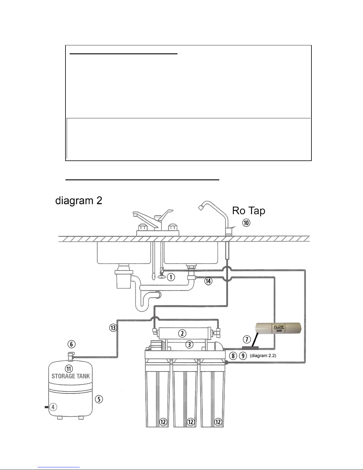
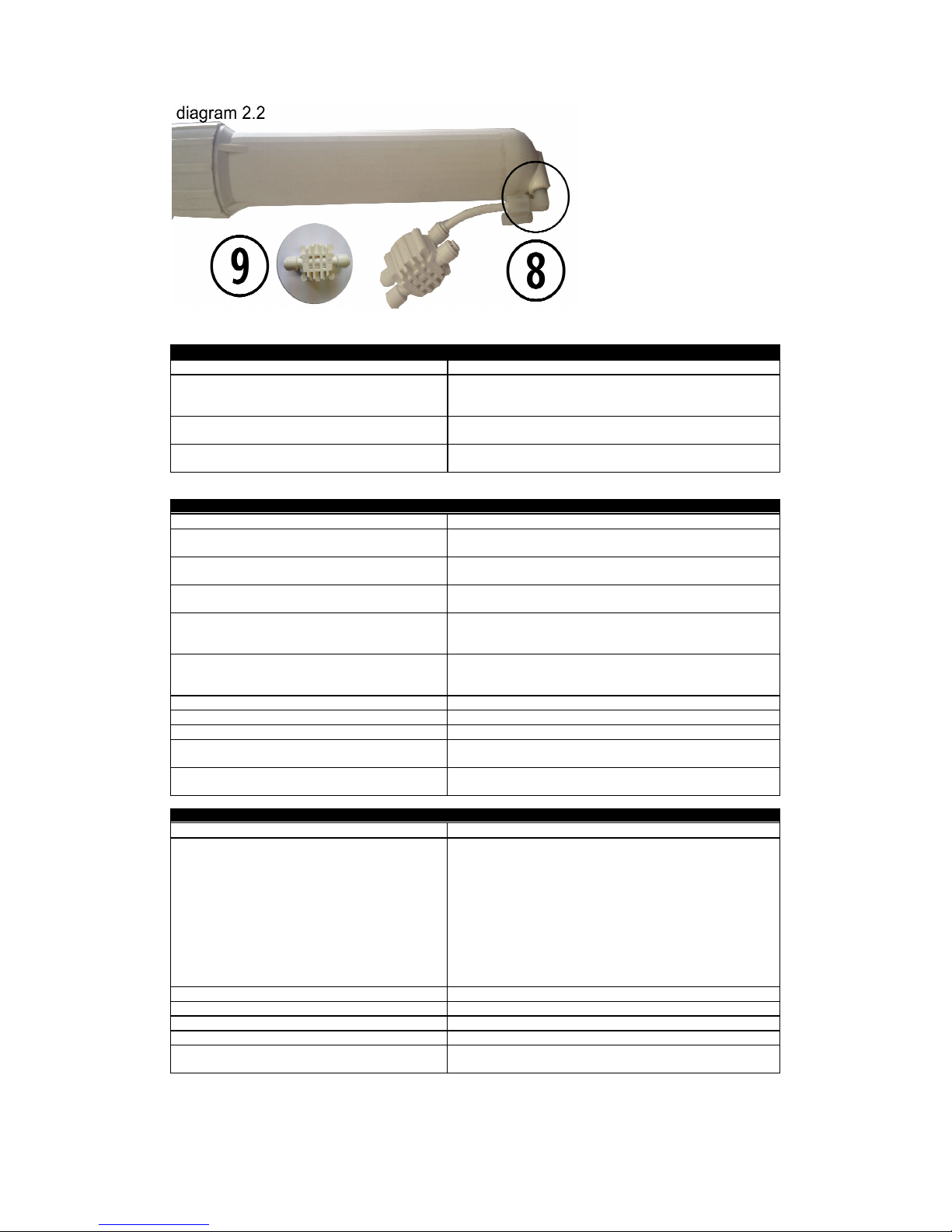
Please refer to diagram 2 when troubleshooting.
If any of the following occur
Cause
Solution
Slow making of product water
Replace the pre-filter cartridge. If the production rate does not
improve, replace post-filter cartridge and reverse osmosis
membrane cartridge.
No product water
Check and make sure the flow restrictor going to train is not
blocked. (7)
Chlorine taste and/or odor
Replace the pre-filter, post-filter and reverse osmosis
membrane cartridges.
The numbers in brackets correspond to diagram 2.
Not
enoug
h water from storage tank
Cause
Solution
Saddle valve (1) is plugged or closed. (very common
on plastic piping)
Open saddle valve (1) or unclog. For plastic piping drill a 3mm
hole as the valve hole tends to close with plastic piping.
Sediment/carbon pre-filter or carbon post filter is
clogged. (2)
Replace filters. (2)
Low incoming water pressure.
Incoming water pressure must be above 2 bar (30 psi). Install a
booster pump.
Reverse osmosis membrane is fouled. (3)
Make sure incoming water pressure is within operating limits.
Make sure drain line is not clogged. (see high tds) correct
cause of fouling and replace ro membrane.
A
ir pressure in storage tank is incorrect. (4)
please watch our video on how to service the revers
e
osmosis storage tank. www.water2buy.com/help
Empty water from storage tank. Air pressure in storage tank
should be between 0.6 bar (9 psi). (4)
A
ir bladder in storage tank is ruptured. (5)
Replace storage tank. (5)
Storage tank valve is closed.(6)
Open valve. (6)
No water to drain. Drain flow restrictor is clogged (7) Replace drain flow restrictor. (7)
No water to drain or constant flow to drain. Non
return valve blocked or faulty (8) see diagram 2.2
Replace non-return valve. (8) see diagram 2.2
The automatic shut-off valve is malfunctioning. (9)
see diagram 2.2
Replace automatic shut-off valve. (9) see diagram 2.2
Low water
pressure from tap
Cause
Solution
A
ir pressure in storage tank is incorrect. (11)
This is the no.1 reason for low flow from reverse
osmosis tap.
Please watch our video on how to service the
reverse osmosis storage tank.
www
.water2buy.com/help
Open tap (10) and empty water from storage tank. Shut off fee
d
w
ater to unit (1) and remove storage tank (11) from under sink.
( The tank is easier to work on.)
Locate the air valve stem (4) (just like on a car or bicycle tire)
and add air. If there is still water in the tank, continue to add a
ir
until all the water is removed.
Once all the water is removed, continue to add air and
pressurize to 0.6 bar (9 psi).
Re-install the tank under the sink, turn on the feed supply to th
e
unit (1) and allow the tank to fill. (if tank does not pressurise
then you need to replace the tank)
Carbon post filter is clogged. (2)
Replace post filter. (2)
Storage tank valve is partially closed. (6)
Open valve. (6)
The tap is out of adjustment or faulty. (10)
Repair or replace tap. (10)
Heavy water use. Storage tank is empty. (11)
A
llow storage tank to refill.
Low water production.
See previous section on low quantity of water from storage
tank.
14
15
Tastes and
odours in wate
r
Cause
Solution
Carbon post filter is exhausted. (2)
Replace filter. (2)
There is foreign matter in storage tank. (11)
Clean, flush and sanitize the storage tank. Replace filters. (11)
Product water and drain water lines are reversed. Correct plumbing.
Dissolved gases in feed water.
Pretreat feed water to remove gasses.
Increase in product water tds. (total dissolved solids) See high tds in product water section
P
roduct water is high in total dissolved solids (tds
)
Cause
Solution
Clogged pre-filter. (12)
Replace filters. (12)
Low incoming water pressure.
Incoming water pressure must be above 2 bar (30 psi). Install a
booster pump.
Reverse osmosis membrane is not correctly
sealed in membrane housing. (3)
Check that reverse osmosis membrane (3) is correctly installed.
Reverse osmosis membrane is expended. (3)
If membrane life is unusually short, find and correct the problem.
(average life is 2 - 3 years.) Replace reverse osmosis membrane. (3
)
Product water and drain water lines are
reversed. (13) (14)
Correct plumbing. (13) (14)
13 – product water
14 – drain water
No water to drain. Drain flow restrictor is
clogged. (7)
Replace drain flow restrictor. (7)
No water to drain. Restrictor valve is clogged.
(7)
Clear or replace restrictor valve. (7)
The automatic shut-off valve is not closing or
diaphragm has ruptured. (9) see diagram 2.2
Repair or replace automatic shut-off valve. (9) see diagram 2.2
New carbon post filter has not been rinsed
completely. (2)
Drain storage tank twice to rinse new carbon post filter. (2)
The incoming feed water tds has increased.
A
n increase in feed water tds will also give an increase in product
w
ater tds.
Tap leaks or drip
s
Cause
Solution
Water leaks from tap spout. (10)
Repair or replace the tap. (10)
Leaks from beneath the handle. (10)
Repair or replace the tap. (10)
Thank you for choosing Water2buy™ water filtration made easy.
© Copyright notice. Water2buy™ is a registered trademark; all images, logos text and diagrams belong to water2buy.
Copying of water2buy™ materials is strictly forbidden without prior written consent.
16
Sicherheitsrichtlinien
Sie müssen Ihre Wasserleitungen schließen, bevor Sie die Umkehrosmoseanlage einbauen.
Water2buy™-installationsrichtlinie:
Alle installationsarbeiten müssen in einer sauberen und
fachgerechten art in einklang mit den allgemein anerkannten handelspraktiken ausgeführt
werden. Überdies müssen alle installationen alle lokalen gesetze, vorschriften, regelungen
und verordnungen einhalten.
Lesen sie alle schritte, anweisungen und regeln sorgfältig durch, bevor sie ihre
umkehrosmoseanlage installieren und verwenden. Befolgen sie alle schritte genau, um sie
korrekt zu installieren. Diese anleitung zu lesen, wird ihnen dabei helfen, alle vorteile ihrer
umkehrosmoseanlage zu nutzen.
Versuchen sie nicht, dieses produkt zu verwenden, um sauberes trinkwasser aus quellen von
nicht trinkbarem wasser zu gewinnen. Verwenden sie die anlage nicht für mikrobiologisch
bedenkliches wasser oder wasser unbekannter qualität.
Fragen sie bei ihrem lokalen wasserwerk nach den leitungs- und sanitärvorschriften. Sie
müssen sich bei der installation der anlage an ihre anweisungen und vorschriften halten.
Diese anleitung beschreibt eine empfohlene installationsmethode, befolgen sie ihre lokalen
vorschriften, wenn diese von den in dieser anleitung gegebenen anweisungen abweichen.
Die umkehrosmoseanlage ohne pumpe funktioniert mit einem wasserdruck von mindestens
1,7 bar (25 psi) bis höchstens 6 bar (90 psi). Wenn der wasserdruck in ihrem haus das
maximum überschreitet, installieren sie ein druckreduzierventil in der zuleitung zur
umkehrosmoseanlage.
Die umkehrosmoseanlage mit pumpe funktioniert mit einem wasserdruck von mindestens 1
bar (15 psi) bis höchstens 6 bar (90 psi). Wenn der wasserdruck in ihrem haus das
maximum überschreitet, installieren sie ein druckreduzierventil in der zuleitung zur
umkehrosmoseanlage.
Installieren sie die umkehrosmoseanlage nicht im freien oder unter extrem heißen oder kalten
temperaturverhältnissen. Die temperatur des der umkehrosmoseanlage zugeleiteten wassers
muss zwischen 5 °c und 40 °c liegen.
Installieren sie nicht an heißwasserleitungen .
Die
umkehrosmosemembran
wird in einer luftdicht verschlossenen hülle für lagerung und
versand geliefert.
Achtung: chlor im wasser wird die umkehrosmosemembran zerstören.
Die meisten städte fügen dem wasser chlor hinzu, um bakterien
abzutöten. Der vorfilter eliminiert das chlor, bevor es in die
umkehrosmosemembran gelangt. Es ist wichtig, die filterkartuschen
mindestens alle 12 monate auszutauschen.
Wo soll die umkehrosmoseanlage installiert werden
Die umkehrosmoseanlage und der speichertank sind für die installation unter der spüle
konzipiert, üblicherweise in der küche. Die umkehrosmoseanlage kann an einer wandfläche
montiert werden oder auf dem schrankboden neben dem speichertank aufgestellt werden.
Der wasserhahn für das produkt der umkehrosmose wird auf der spüle oder auf der
arbeitsfläche neben der spüle installiert.
Bitte beachten sie: die länge der leitungen sollte die entfernung der anlage von den
aufhängungen zwecks wartung erlauben. Wenn die die leitungen aus optischen gründen
gekürzt werden, kann es notwendig sein, die anlage während der wartung an den
aufhängungen zu belassen.
Sie können auch die umkehrosmoseanlage und den speichertank an einer beliebigen stelle in
einiger entfernung vom wasserhahn anbringen, sofern sie die sicherheitsrichtlinien auf seite 2
beachten. Sie benötigen eine wasserquelle und eine ablaufstelle in der nähe.
17
Einbau Ihrer Umkehrosmoseanlage
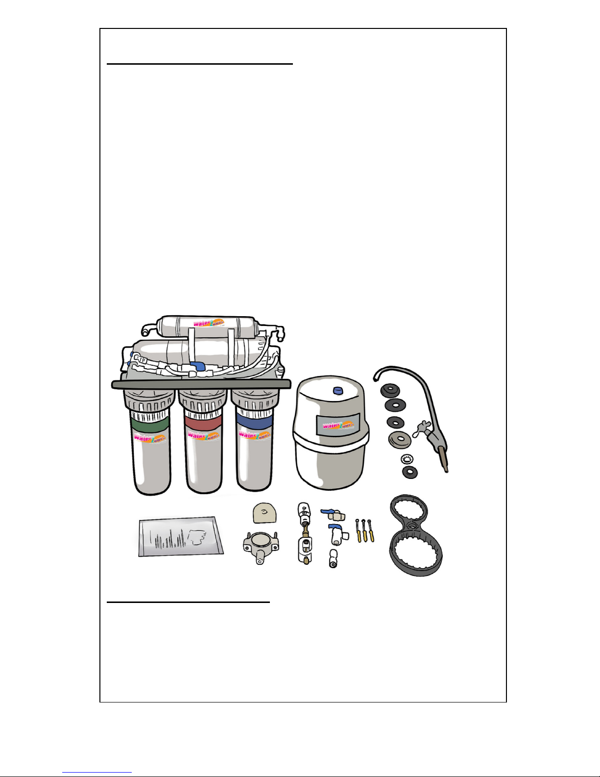
Mitgelieferte Teile prüfen: Öffnen Sie die Verpackung und entfernen Sie die
Umkehrosmoseanlage. Zusätzlich zur zusammengebauten Umkehrosmoseanlage und dem
Vorratsbehälter enthält die Einheit die folgenden Teile:
•
Umkehrosmoseeinheit
•
Vorratsbehälter
•
Hahn, Unterlegscheiben und Schnellverschluss
•
Handbuch
•
Abflussklemme
•
Sattelventil
•
Wassereinlassverbinder und Ventil
•
Halterung (dort verwenden, wo Sie den Hahn direkt an der Einheit anbringen möchten)
•
Tankventil
•
Gehäuseschlüssel
•
Befestigungsschrauben
•
Rohre
•
Netzteil (RO 600, RO 650 & RO 700 modelle)
•
Mineralischen Filter (RO 550 & RO 650 modelle)
•
UV Filter (RO 700 modelle)
Benötigte Werkzeuge und Materialien
•
Verstellbarer Schraubenschlüssel / Rohrzange
•
Zange
•
Rohrzange für Spüle
•
Schraubenzieher
•
Teflonband oder Rohrverbundmaterial (Gewindedichtung, freigegeben zur Verwendung
für Trinkwasserversorgung)
•
Bohrmaschine mit 3-mm-, 5-mm- und 12-mm-Bits.
Beachten Sie beim Lesen von Einbauschritten dieses Diagramm
18
Montagean
leitung:
19
Schritten 1
A:
Schrauben Sie mithilfe
des mitgelieferten
Schlüssels die 3
Filtergehäuse ab.
B:
Entfernen Sie die Filter
aus der Verpackung.
Platzieren Sie die Filter in
den Gehäusen.
C:
Platzieren Sie den ORing oben auf dem
Gehäuse. Schrauben Sie
das Gehäuse mit der Hand
wieder an die
Umkehrosmoseeinheit.
D:
Ziehen Sie die
Filtergehäuse mit dem
Schlüssel an.
Montagean
leitung:
20
E:
Stellen Sie sicher, dass
die Filter sich in dem jeweils
korrekten Gehäuse
befinden.
Water2buy-Filter sind
farbkodiert. Von rechts
nach links:
PP (blau markierter Filter)
GAC (rot markierter Filter)
CTO (grün markierter Filter).
21
Montagean
leitung:
Schritten 2
A:
Trennen Sie die Rohre
vom Membrangehäuse,
um Zugriff darauf zu
erhalten. Schrauben Sie
den Deckel mithilfe des
mitgelieferten Schlüssels
ab.
B:
Entfernen Sie die
Membran aus der
Verpackung. Entfernen Sie
alle etwaigen schwarzen
Stecker aus den
Membranenden.
C:
Stecken Sie die
Membran korrekt ein (wie
dargestellt).
D:
Platzieren Sie den
Gehäusedeckel darauf und
ziehen Sie ihn mit dem
Schlüssel fest. Platzieren
Sie die Rohre wieder an
ihrem Ort.
22
Montagean
leitung:
Schritten 3
A:
Bohren Sie ein 12-mmLoch ins Spülbecken oder
in die Arbeitsplatte, um
den Hahn zu montieren.
Sichern Sie den Hahn
mithilfe der
Unterlegscheiben am
Spülbecken (wie
dargestellt).
B:
Drücken Sie den
Schnellverschluss in die
Basis des Hahns.
C:
Verbinden Sie
die
Rohre
des Inline-Filters mit
dem Hahn, wie es im
Referenzdiagramm
anhand des blauen Rohrs
(2) dargestellt wird.
23
Montagean
leitung:
Sie können Schritt 4.1 oder 4.2 verwenden. Verwenden Sie nicht beides!
Schritten 4.1
A:
Suchen Sie das
Hauptwasserrohr unter
dem Spülbecken. Stellen
Sie sicher, dass Sie die
Wasserversorgung
abgestellt haben.
B:
Bringen Sie das
Sattelventil am Kupferrohr
der Wasserleitung an; wird
das Sattelventil an einem
Kunststoffrohr angebracht,
müssen Sie zuerst ein 3mm-Loch bohren, da die
Einheit ansonsten
eventuell nicht mehr
funktioniert.
Schritten 4.1
C:
Verwenden Sie den
Kunststoffeinsatz und
Kunststoffring des Rohrs.
Verbinden Sie das Rohr
des Sattelventils mit dem
ersten Filter, wie es im
Referenzdiagramm
anhand des roten Rohrs
(3) dargestellt wird.
D:
Drehen Sie das
Sattelventil im
Uhrzeigersinn, um ein
Loch in das Rohr zu
stechen, und öffnen Sie es
dann vollständig (gegen
den Uhrzeigersinn
drehen). Ist es nur halb
geöffnet, könnte es lecken.
Wenn es leckt, ziehen Sie
die Mutter am Sattelventil
an.
24
Montagean
leitung:
Schritten 4.2
Schritten 4.2
A:
Schrauben Sie den
Kaltwasserhahn an der
Verbindung von der
Wasserversorgung ab.
B:
Umwickeln Sie den
Wassereinlassverbinder
und das Ventil mit
Teflonband.
C:
Stecken Sie den
Wassereinlassverbinder
zwischen dem Hahn und
der
Wasseranschlussverbindu
ng ein. Ziehen Sie ihn an,
sodass er wasserdicht ist.
Schrauben Sie das Ventil
in den
Wassereinlassverbinder.
D:
Verbinden Sie das
Rohr des Ventils mit dem
ersten Filter, wie es im
Referenzdiagramm
anhand des roten Rohrs
(3) dargestellt wird.
25
Montagean
leitung:
Schritten 5
A:
Bohren Sie ein 5-mmLoch in das Abflussrohr
über dem Siphon und
bringen Sie die
Abflussklemme an.
B:
Stellen Sie sicher, dass
die Unterlegscheibe
verwendet wird.
C:
Verbinden Sie das
Abflussrohr von der
Umkehrosmoseeinheit mit
der Abflussklemme, wie es
im Diagramm anhand des
schwarzen Rohrs (4)
dargestellt wird..
Wichtig:
Es wird empfohlen, den Vorratsbehälter vor der Verwendung zu desinfizieren. Geben Sie dazu 1-2
Tropfen Desinfektionsmittel in den Vorratsbehälter (Verwenden Sie water2buy™-, Milton™- oder sonstige
Desinfektionsmittel die zur Verwendung mit Trinkwasser sicher sind).
26
Montageanleitung:
Schritten 6
A:
Schrauben Sie das
Ventil oben auf den
Umkehrosmosetank.
Stellen Sie sicher, dass
Sie die Unterlegscheibe
verwenden, um die
Verbindung abzudichten.
B:
Verbinden Sie den
Tank mit dem Filter, wie es
im Referenzdiagramm
anhand des lila Rohrs (5)
dargestellt wird.
C:
Öffnen Sie das Ventil
oben auf dem Behälter.
System nach dem Einbau überprüfen
Schalten sie die Wasserversorgung ein.
Prüfen Sie alle Gelenke und Verbindungen auf Dichtheit.
Warten Sie, bis das gesamte System unter Druck steht.
Lassen Sie es drei Stunden stehen.
Prüfen Sie alle Gelenke und Verbindungen erneut auf Dichtheit.
Drehen Sie den Wasserhahn auf, bis kein Wasser mehr läuft und der Druckbehälter leer ist.
Es ist normal, dass beim Entleeren der ersten zwei Behälterladungen etwas Feinkohle im Wasser erscheint.
Die ersten zwei Behälterladungen Wasser sollten nicht verwendet werden.
Prüfen Sie das System nach zwei Stunden erneut auf Dichtheit, dann sollte es bereit zur Verwendung sein.
Wenn Sie weitere Hilfe benötigen, sehen Sie sich das Einbau-Video unter
www.water2buy.com an.
 Loading...