

Watec WAT-910HX/RC Operating Manual
Danger
Danger
Danger
Multi Function / Super High Sensitivi ty
WAT-910HX/RC
Operation Manual
This Operation Manual covers safet y, camera functions, installation an d
the correct operating procedure for the WAT-910HX/RC. First, we ask
you to read this Operation Manual thoroughly, then install and operate
the WAT-910HX/RC as advised. I n addition, for future referenc e, we
also advise safekeeping of this manual .
Please contact the distributor or dealer from which the WAT-910HX/RC
was purchased, if you do not understand the installation, operati on or
safety instructions laid out in this manual. Not under standing the
contents of the Operation Manual s ufficiently may cause damage to the
camera.
Guide to the Safety Symbols
The definitions of the symbols used i n this operation manual are:
When you do not adhere to or take notice of t he “Danger”
sign, it may lead to a serious accident such as death or
injury caused by fire or electri c shock.
When you do not adhere to or take notice of the “Warning”
sign, it may cause severe damage such as a physic al injury.
When you do not adhere to or take notice of the “Caution”
sign, it may incur injury and cause damage t o peripheral
objects in the immediate surroundings .
Cautions for Safety
The WAT-910HX/RC is des igned to be used safely; however, if not
used safely, it may lead to a physical accident caus ed by fire and
electric shock. Therefore, plea se keep and read the “Cautio ns for
safety” below for protection agains t accidents.
• Do not disassemble and/or modify the WAT-910HX/RC.
•
Do not operate the WAT-910HX/RC with wet hands.
• Use a stabilized power adaptor designed for DC+12V
±
10%, with a current capacity of more than 250m A for
the WAT-910HX/ RC.
The recommended voltage is DC+12V±10%
• Do not expose the WAT-910HX/RC to wetness or high
moisture conditions.
The WAT-910HX/RC is designed and approved for indoor
use only. The WAT-910HX/RC is not water-resistant or
waterproof. If the location of t he camera is outdoors or in
an outdoor like environment, we recom mend that you use
an outdoor camera housing.
• Protect the WAT-910HX/RC from condensation.
Keep the WAT-910HX/RC dry at all times during storage
and operation.
• Should the camera not work properly, switch off the power
immediately. Then check the camera according to t he
“Problems and Trouble shooting” section.
• Avoid the striking of hard objects or dropping the
WAT-910HX/RC.
The WAT-910HX/RC uses high quality electrical parts and
precision components.
• Do not connect any power supply directly to the video
out terminal of the unit.
Do not connect the WAT-910HX/RC with any monitor using
a video/power single transmis sion terminal. The WAT910HX/RC is not designed for use with this type of
equipment. We also advise you to read the oper ation
manual of the monitor you plan to use bef ore any
connections are made.
• Do not install the WAT-910HX/RC in a position subject
to direct sunlight.
Sunlight shinning directly onto t he WAT-910HX/RC lens
can cause damage to the CCD.
• Select a stable place for installation of the
WAT-910HX/RC.
Use a support of durable strength around an i nstallation
position on a ceiling or wall when a cam era stand or tripod
is used.
• Do not move the WAT-910HX/RC with the cables
connected.
Before moving the WAT-910HX/RC, always remov e the
video cable and power cable from the rear of the camera
first.
• Avoid using th e WAT-910HX/ RC near any strong
electromagnetic field.
After installing into main equipment, if the WAT-910HX/RC
is exposed to electromagnetic waves causing the
monitored image to become distort ed, we recommend the
camera be shielded by appropriate prot ective casing.
Problems and Trouble Shooting
If any of the following problems occur when using the
WAT-910HX/RC,
• An optimal picture cannot be obtained, after checking that all the
cables and connections are correct ly in place
• Smoke or any unusual odor emerges fr om the WAT-910HX/RC
• An object becomes embedded or a quantit y of liquid seeps into the
camera housing
• More than the recommended voltage or/an d amperage has been
applied to the WAT-910HX/RC by mistake
• Anything unusual occurring to any equipm ent connected to the
WAT-910HX/RC
Disconnect the camera immediately according to t he following
procedures:
①
Switch off the main power supply to the camera.
②Remove the power and video cables connected to th e WAT-910HX/RC.
③Contact the distributor or dealer from which the WAT-910HX/RC was
purchased.
About EMC
The WAT-910HX/RC is in conformity with EMC test standards carried
out by authorized organizations in Japan.
E I A FCC Part15 class B
CCIR EN61000-6-3/EN50130-4
※Please use an auxiliary power supply (eg: UPS) to this cam era to comply
with EN50130-4 of EMC standards.
Do not modify the WAT-910HX/RC. A modified camera
may not conform to EMC test standards.
Contents
Using the contents figures below, check to make sure al l parts are
present before use.
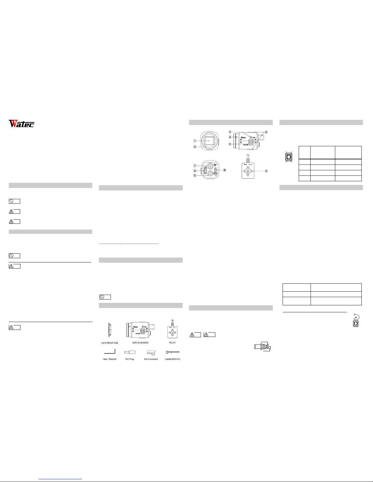
Description of Parts
①IMAGE SENSOR FRONT FACE
・
The light receiving face of the image sens or
(Dirt, water or oil deposits on the image sensor wil l cause an unclear
picture on the monitor. Attach the lens cap to protect the lens and the
CCD from contamination and damage.)
②LENS MOUNT
・
Mount for the lens (CS-mount)
③IRIS LEVEL VOLUME
・By controlling the volume, the ir is level of the DC iris lens can be
adjusted.
④FINE FOCUS ADJUSTMENT SCREWS
・
There are 3 hex. adjustment screws eac h placed at intervals of 120゜
for fine focusing of the lens.
⑤AUTO-IRIS SOCKET
・
This socket is for the video/DC auto-ir is lens cable connector.
(Video/DC: Auto selected by the camera)
⑥TRIPOD MOUNTING SCREW HOLES
・
Mounting holes for stands. The size of these t hreads are 1/4”, 20
threads, 4.5±0.2mm, which is the same as any standard camera
tripod (U1/4”).
⑦VIDEO OUT (BNC)
・
The terminal for composite video signal output
⑧OSD(On Screen Display) CONNECTOR
・
The terminal designed for connection wi th the remote control for
setting the functions on the scr een.
⑨POWER IN
・
The terminal designed for connection wi th the DC-plug of the power
adaptor.
⑩I/O CONNECTOR
・
The control terminal for the Motion Detecti on.
⑪OPERATION BUTTON
・
The operation button for setting the f unctions on the screen.
Power Supply
Use a stabilized power adaptor designed for DC+12V±10%, with a
current capacity of more than 250mA. Use the optional D C plug if the
shape or polarity of the DC plu g of the power adaptor to be used is not
compatible with the camera (See the drawi ng on the right below).
The wiring of the connector must be e xact.
Be careful not to touch the other terminal while
wiring. Protect the wiring porti on by using insulation
tape after wiring. If the above care and attentio n is
not adhered to, damage to the WAT-910HX/RC and
power adaptor may occur and may also c ause fire.
Auto-iris Lens
Before connecting the auto-ir is lens, please make sure that t he pin
configuration is correct by c onfirming with the following table. If the
configuration of your iris conne ctor is different from the followi ng, the
plug and pins will need to be rewired.
Pin No.
EIAJ Video
Auto-iris Lens
Arrangement
EIAJ DC
Auto-iris Lens
Arrangement
①
Power
Control -
②
Not used
Control +
③
Iris signals
Drive +
④
Common (GND)
Drive -
Set-up and Operation
1) Ensure that the power to the WAT-910HX/RC and the peripheral
equipment is turned off before making any c onnections.
2) Remove the lens mount cap from the WAT-910HX/RC and attach the
CS-mount lens. Use the optional C-mount adapt or (30CMA-R) when
a C-mount lens is used.
3) Connect the iris control c able to ⑤AUTO-IRIS SOCKET on the
WAT-910HX/RC when an auto-ir is lens is being used.
4) Connect ⑦VIDEO OUT on the WAT-910HX/RC with the monitor,
using a coaxial cable with 75Ω impedance, suc h as an RG-59 or an
RG-6/U.
※Select a monitor with the same televis ion system as the WAT-
910HX/RC EIA or CCIR. A monitor with more than 600TV lines is
recommended.
5) Insert the power plug of the power adaptor into ⑨POWER IN on the
back panel of the WAT-910HX/RC. Confirm that the power adaptor is
not connected to the power supply before ins ertion of the power plug
into ⑨POWER IN.
6) Turn on the power to the WAT-910HX/RC, monitor and all other
allied equipment. When a picture cannot be obtained on t he monitor,
or a problem occurs, check and follow the procedure mentioned in
the【Problems and Trouble Shooting】section.
7) After following the procedure below and the picture i s still out of
focus, open the iris fully and loosen ④FINE FOCUSING
ADJUSTMENT SCREWS with the hex. wrench and mo ve the lens
forwards until a clear picture is obtai ned.
Manual Lens
Adjust the focus and iris to the best
position on the lens.
Video Auto-iris Lens Adjust the focus on the lens.
DC Auto-iris Lens
Adjust the iris level on the camera, then
adjust the focus on the lens. See below.
Iris Level Adjustment (for DC auto-iris lenses on ly)
Adjust ③IRIS LEVEL VOLUME placed on the side
of the unit until an acceptable light level is attained.
No change will occur if a video iris lens or manual
iris lens is fitted.
※ When an auto iris lens is used, connect the remote cont rol
to ⑧OSD(On Screen Display) CONNECTOR, then set
SHUTTER to 1/60 (1/50), SENS UP to OFF and AGC to OFF by
⑪OPERATION BUTTON. Then adjust ③IRIS LEVEL VOLUME
until an acceptable light level is attained.
8) When detailed settings are required or an a dequate image is not
obtained, connect the remote control to ⑧OSD(On Scr een Display)
CONNECTOR, then set the functions on the screen by
⑪OPERATION BUTTON.
Warnin g
LEVEL
CLOSED
OPEN
DC+12V
COMMON(GND)
Cautio n
Warnin g
Cautio n
①
②
③
④
Warnin g
Cautio n

9) When controlling the motion detection function, connect to ⑩I/O
CONNECTOR after wiring using the attached cable. See the pin
configuration as follows.
PIN No. Cable color Title Function
1
Brown MD_O Alarm out
2 Black GND Camera GND
3 - NC
■Alarm output terminal
When the motion detection function is used, the alarm output terminals
1 and 2 are hot during detection of movement in the monitored area.
If an LED is connected as shown in the diagram below, the alert turns
on the LED by voltage output of 3.3V at maximum current of 6mA.
Options
To purchase these options, please contact the distributor or dealer from
which you purchased the WAT -910HX/RC.
Contact information
Contact information
Watec Co., Ltd.
Add.:I 254-2 Nihonkoku, Daihoji, Tsuruoka- Shi,
Yamagata-Ken, 997-0017 Japan
TEL: +81-235-23-4400 FAX: +81-235-23-4409
E-mail: info-o@watec.co.jp
URL: http://www.watec.co.jp
• Design and specifications are subject to change without notice.
• Watec is not responsible for any inconvenience or the attendant damages
to the video and monitoring recording equipment caused by misuse, misoperation or improper wiring of our equipment.
• If for any reason the WAT-910HX/RC does not work properly, or if you
have any questions regarding installation or operation, please contact the
distributor or dealer from which it was purchased.
※Mimimum illumination specification applies to cameras with serial
numbers from W154BE01001/W154BC01001 and higher.
C-mount Adaptor (30CMA-R)
This lens mount adaptor is used
to convert a CS-mount to a Cmount.
Mini Stand (MS50)
A convenient stand for the
WAT-910HX/RC. With this stand,
the camera can be adjusted to
any desired angle.
1542Z00-Y2000013
 Loading...