

Watec WAT-902HB Series Operation Manual
Danger
Danger
Monochrome Board CCD Camera
WAT-902HB Series
Operation Manual
This Operation Manual covers safety, camera functions, installation and the
correct operating procedure for the WAT-902HB series. First, we ask you to read
this Operation Manual thoroughly,then install and operate the WAT-902HB series
as advised. In addition, for future reference, we also advise safekeeping of this
manual.
Please contact the dis tributor or dealer fr om which the WAT-902HB series was
purchased, if you do not understand the installation, operation or safety
instructions laid out in this manual. Not understanding the contents of the
Operation Manual sufficiently may cause damage to the camera.
Guide to the Safety Symbols
The definitions of t he symbols used in this operation manual are:
When you do not adhere to or take notice of the “Danger” sign, it
may lead to a serious accident such as death or injury caused by fire
or electric shock.
When you do not adhere to o r take notice of the “Warning” sign, it
may cause severe damage such as a physical injury.
When you do not adhere to o r take notice of the “Caution” sign , it
may incur injury and cause damage to peripheral objects in the
immediate surroundings.
Cautions for Safety
The WAT-902HB series is designed to be used safely; however, it may lead to a
physical accident caused by fire and electric shock if not used correctly.
Therefore, please keep and read the “Cautions for safety” below for protection
against accidents.
• Do not disassemble and/or modify the WAT-902HB series.
• Do not operate the WAT-902HB series with wet hands.
• Use a stabilized power adaptor designed for DC+12V±10%,
with a current capacity of more than 250mA for the
WAT-902HB series.
The recommended volta ge is DC+12V±10%
• Do not expose the WAT-902HB series to wetness or high
moisture conditions.
The WAT-902HB series is designed and approved for indoor use
only. The WAT-902HB series is not water-resistant or waterproof. If
the location of the camera is outdoors o r in an outdoor like
environment, we recommend that you use an outdoor camera
housing.
• Protect the WAT-902HB series from condensation.
Keep the WAT-902HB series dry at all times durin gstorage and
operation.
• Should the camera not work properly, switch off the power
immediately. Then, check the camera according to the“Probl ems
and Trouble shooting”s ection.
• Avoid the striking of hard objects or dropping the WAT-902HB
series.
The WAT-902HB series uses high quality e lectrical parts and
precision components.
• Do not connect any power supply directly to the video
out terminal of the unit.
Do not connect the WAT-902HB series with any monitor using a
video/power single tra nsmission terminal . The WAT-902HB series
is not designed for use with this type of equipment. We also advise
you to read the operation manual of the monitor you plan to use
before any connections are made.
• Do not install the WAT-902HB series in a position subject to
direct sunlight.
Sunlight shinning directly onto the WAT-902HB series lens can
cause damage to the CCD.
• Select a stable place for installation of the WAT-902HB series.
Always fix the camera securely. See【Mounting Holes】section.
• Do not move the WAT-902HB series with the cables
connected.
Before moving t he WAT-902HB series, always remove the v ideo
cable and power cable from the camera first.
• Avoid using the WAT-WAT-902HB series near any strong
electromagnetic field.
After installing i nto main equipment, if the WAT-9 02HB series is
exposed to electromagnetic waves causing the monitored image to
become distorted, we recommend the camera be shielded by
appropriate pr otective casing.
Problems and Trouble Shooting
If any of the following problems occur when using the WAT- WAT-902HB
series,
• An optimal picture cannot be obtained, after checking that all the cablesand
connections are correctly in place
• Smoke or any unusual odor emerges from theWAT -902HB series
• An object becomes embedded or a quantity of liquid seeps into the camera
• More than the recommended voltage or/and amperage has been applied to the
WAT-902HB series by mistake
• Anything unusual occurring to any equipment connected to the WAT-902HB
series.
Disconnect the camera immediatel y according to the following procedures:
①Switch off the main power supply to the camera.
②Remove the power and video cables connected to the WAT-902HB series.
③Contact the distributor or dealer from which the WAT-902HB series wa s
purchased.
Contents
Using the contents figures below, check to make sure all parts are present before
use.
WAT-902HB Lens Mount Cap Connector with cables Hex. Wrench
Description of Parts
①LENS FRONT FACE
・
The light receiving face of the lens
(Dirt, water or oil deposits on the lens will cause an unclear picture on the
monitor. Attach the lens cap to protect the l ens from contaminat ion and
damage.)
②LENS MOUNT
・
Mount for the lens (Thread type)
③FINE FOCUS ADJUSTING SCREWS
・
There are 3 hex. adjus tment screws each placed at interv als of 120゜for fine
focusing of the len s.
④POWER IN/VIDEO OUT
・
The terminal for power i nput and video signal output. Use the attached
connector with cables for this purpose.
⑤TERMINAL FO R AUTO-IRIS LENS (VIDEO CONTROL)
・
The terminal for a Video-driven auto-iris lens. Do not connect a DC-driven
auto-iris lens to this terminal.
⑥MOUNTING HOLES
・
Holes for mounting the camera.
⑦AGC SELECTION SWITCH
・
Switch for setting AGC HI or LO
Power Supply and Wiring
Use a stabilized power adaptor designed for DC+12V±10%, with a current
capacity of mor e than 250mA.
The wiring on the connector must b e exact.
Be careful not to touch the other terminals while wiring. Protect the wired portion
by using insulation tape. If the above care and attent ion is not adhered to,
damage to the WAT-902HB series and power adaptor may occur and may also
cause fire.
Mounting Holes
As shown in the figure on the right. The WAT-902HB series
provides four mounting holes(φ2.2mm), one in each corner of
the circuit bo ard. Fix the unit secure ly using M2 screws. Once
the board is secured proceed with the following steps below.
Set-up and Operation
1) Ens ure that the power to the WAT-902HB series and the peripheral equipment
is turned off before making any connections.
2) R emove the lens mount cap f rom the WAT-902HB series.
3) Wh en an auto iris lens is being used, connect the cable to ⑤TERMINAL FOR
AUTO-IRIS LENS.
※Do not connect a DC cont rol iris lens to this camera.
4) Connect the attached cable to ④POWER IN/VIDEO OUT. See the【Power
Supply and Wiring】section.
5) Connect a coaxial cable with 75Ω impedance, such as an RG-58/U or an
RG-6/U to the monitor. Select a monitor with the same television system as
the WAT-902HB series: EIA or CCIR. A monitor with more than 600TV lines is
recommended.
6) Turn on the power to the WAT-902HB series, monitor and all other allied
equipment. When a p icture cannot be obtained on the monitor, check and
follow the procedure mentioned in the【Problems and Trouble Shooting】
section.
7) After following the procedure below and the picture is still out of focus, open
the iris fully a nd loosen ③FOCUSING ADJUSTMENT SCREWS with the hex.
wrench and move the lens forwards until a clear picture is obtained.
Manual Lens
Adjust the focus and iris to the best position on
the lens.
Video Auto-iris Lens Adjust the f ocus on the lens.
8) S et the AGC mode by ⑦AGC SELECTION SWITCH.
Mode Range Effect
HI
5~50dB
・When minimum il lumination is more
important than the SN ratio
(Surveillance in a low light environment)
LO
5~32dB
・When SN ratio is more important than
minimum illumination.
・When adequate lig hting is present or a
stable lighting condition is availabl e.
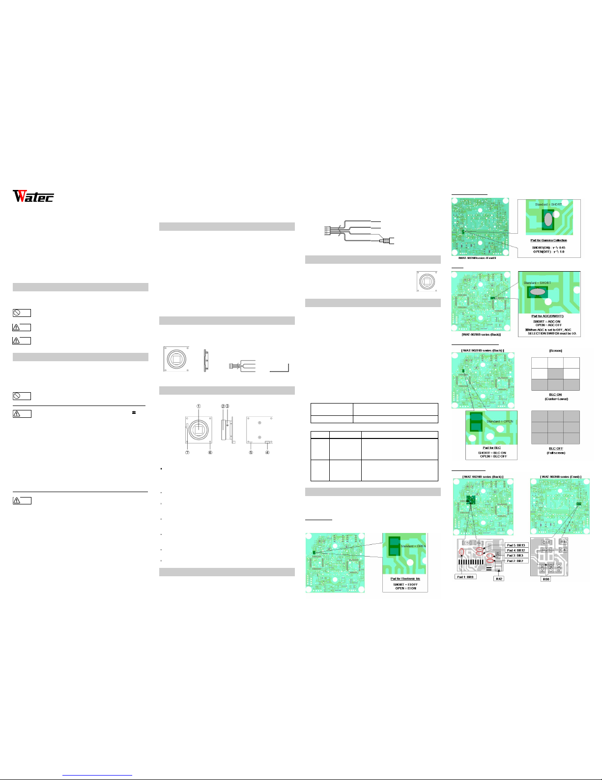
Function Setting
There are vario us function settings on th e circuit board of the WAT-902HB series.
To change the function preferences re-solder the settings to your requirement.
■Electronic Iris
■Gamma Correction
■AGC
■Back Light Compens ation
■Electronic Shutter
※When the function is returned to electronic iris mode, be sure to reinstall the
resistor. Therefore, we recommend safe keeping of the resistor.
Warnin g
Cautio n
Warnin g
Cautio n
Red: DC+ 12V
Black : Com mon G ND
Blue: Vi deo o ut
To po wer s upply (DC+ 12V )
Black : Com mon G ND
To po wer s upply (GND )
To 75Ωcoax. cable
for monitor
• Design and specifications are subject to change without notice.
• Watec is not responsible for any inconvenience or the attendant damages
to the video and monitoring recording equipment caused by misuse, misoperation or improper wiring of our equipment.
• If for any reason the WAT-902HB series does not work properly, or if you have
any questions regarding installation or operation, please contactthe dis tributor
or dealer from which it was purchased.
1200Z00-Y2000006
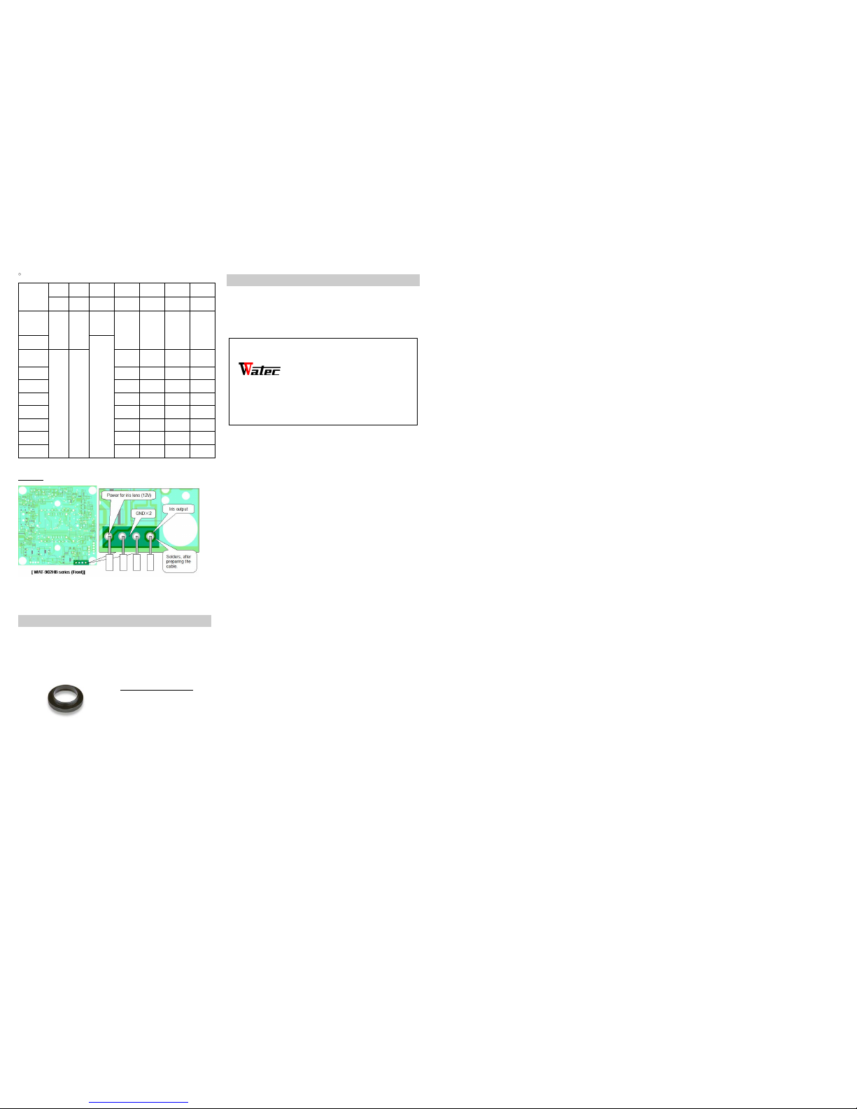
• Pad for electronic shutter function:
[Unit: sec.]
RES RES Pad 1 Pad 2 Pad 3 Pad 4 Pad 5
R68 R42 BR8 BR2 BR3 BR12 BR 13
EI
(EIA: 1/60~
100000)
(CCIR:1/50~
100000)
MOUNT MOUNT
OPEN
OPEN OPEN OPEN OPEN
OFF
(EIA: 1/60)
(CCIR: 1/50)
SHORT
FL
(EIA: 1/100)
(CCIR: 1/120)
NO
MOUNTNOMOUNT
OPEN SHORT SHORT OPEN
1/250 OPEN OPEN SHORT OPEN
1/500 OPEN SHORT OPEN SHORT
1/1000 OPEN OPEN OPEN SHORT
1/2000 SHORT SHORT SHORT OPEN
1/5000 SHORT OPEN SHORT OPEN
1/10000 SHORT SHORT OPEN SHORT
1/100000 SHORT OPEN OPEN SHORT
※The default setting is EI.
■Auto Iris
※WAT-902HB series is designed for a video control auto ir is lens. DC controlled
auto iris lenses are not supported for this camera.
※Cut the cable close to the connector,strip the wires back and then solder to the
appropriate terminals of the WAT-902HB series.
Option
To purchase these options, please contact the distributor or dealer from which
you purchased the WAT-902HB series.
Contact information
Contact information
Watec Co., Ltd.
Add.:I 254-2 Nihonkoku, Daihoji, Tsuruoka- Shi,
Yama gata-Ken, 997-0017 Japan
TEL: +81-235-23-4400 FAX: +81-235-23-4409
E-mail: info-o@watec.co.jp
URL: http://www.watec.co.jp
C-mount Adaptor (30CMA-R)
This lens mount adaptor is used to
convert a CS-mount to a C-mount.
 Loading...