


WAT-2200Mk-2
User’s Manual
Rev. 1.00
Watec Co., Ltd.

2
Revision Record
Rev.
Date
Changes
1.00
2018/12/19
-

3
Table of Contents
Revision Record ..................................................................................................................... 2
Table of Contents .................................................................................................................... 3
1. About this manual............................................................................................................ 5
2. Configuring the camera function ..................................................................................... 6
2.1. RC-02 (Remote Control) .......................................................................................... 6
2.2. RS232 ...................................................................................................................... 7
2.3. OSD Menu Operations............................................................................................. 9
3. Functions ........................................................................................................................ 11
3.1. EXPOSURE ............................................................................................................ 11
3.1.1. AE MODE ........................................................................................................ 11
3.1.2. SHUTTER ....................................................................................................... 12
3.1.3. GAIN ............................................................................................................... 13
3.1.4. AGC MAX ....................................................................................................... 13
3.1.5. SENS UP ........................................................................................................ 13
3.1.6. AE BRIGHT .................................................................................................... 14
3.1.7. DC IRIS ........................................................................................................... 14
3.2. WHITE BALANCE .................................................................................................. 15
3.2.1. WHITE BALANCE MODE(MODE) ................................................................. 15
3.2.2. One Push Trigger(PUSH) ............................................................................... 15
3.2.3. B-Gain(BLUE) ................................................................................................. 15
3.2.4. R-Gain(RED) .................................................................................................. 16
3.2.5. White Balance Tracking Speed(SPEED) ....................................................... 16
3.2.6. B-Gain Offset(OFFSET-B) .............................................................................. 16
3.2.7. R-Gain Offset(OFFSET-R) ............................................................................. 16
3.3. NOISE REDUCTION ............................................................................................. 17
3.3.1. Noise Reduction Mode(MODE) ...................................................................... 17
3.3.2. Noise Reduction Level(LEVEL) ...................................................................... 18
3.4. PICTURE ADJUST ................................................................................................ 19
3.4.1. GAMMA CORRECT ....................................................................................... 19
3.4.2. CONTRAST .................................................................................................... 20
3.4.3. BRIGHTNESS ................................................................................................ 20
3.4.4. SATURATION ................................................................................................. 20
3.4.5. HUE ................................................................................................................ 20
3.4.6. EDGE .............................................................................................................. 20

4
3.4.7. AUTO SATURATE .......................................................................................... 21
3.4.8. AUTO EDGE ................................................................................................... 22
3.4.9. DISPLAY FUNCTION ..................................................................................... 23
3.4.10. Reset Picture Adjust(DEFAULT) ..................................................................... 23
3.5. FUNCTIONS .......................................................................................................... 24
3.5.1. Digital Zoom(DZOOM) .................................................................................... 24
3.5.2. DEFOG ........................................................................................................... 29
3.5.3. DWDR ............................................................................................................. 30
3.5.4. MOTION DETECT .......................................................................................... 31
3.5.5. Digital Image Stabilizer(DIS) .......................................................................... 33
3.5.6. Backlight Compensation(BACKLIGHT) .......................................................... 34
3.5.7. Pixel Binning(BINNING) ................................................................................. 36
3.5.8. DEFECT PIXEL COMPENSATION ................................................................ 37
3.5.9. Multiple Exposure-Type WDR(WDR) ............................................................. 38
3.5.10. PRIVACY MASK ............................................................................................. 40
3.5.11. CROSS LINE .................................................................................................. 42
3.6. SYSTEM ................................................................................................................ 43
3.6.1. S/W INFO ....................................................................................................... 43
3.6.2. CAM TITLE ..................................................................................................... 44
3.6.3. MENU COLOR ............................................................................................... 45
3.6.4. MENU POSITION ........................................................................................... 45
3.6.5. OUTPUT FORMAT ......................................................................................... 46
3.6.6. CVBS FORMAT .............................................................................................. 47
3.7. FACTORY RESET ................................................................................................. 49
4. OSD Menu Tree ............................................................................................................ 50
5. RS232 Command List ................................................................................................... 59

5
1. About this manual
This user manual describes the OSD (On Screen Display) menu of WAT-2200 Mk-2, the
function setting method by RS232, and the details of each function.
When the settings of the WAT-2200 Mk-2 is changed according to this manual, check to
see that the operation and the effects of the changes made to the camera are acceptable.
The WAT-2200 Mk-2 user’s manual is subject to change by design and the specifications of
the product without notice.
The copyright of the WAT-2200 Mk-2 user’s manual shall belong to Watec Co., Ltd.
Copying in whole or in part without the authorization of the holders permission is prohibited.

6
2. Configuring the camera function
The function of WAT-2200 Mk-2 can be set by the RC-02 (remote control) or RS232. Utilize
the option RC-02 (remote control) to set function through OSD (On Screen Display) menu.
By RS232, through communication by the VISCA/Pelco-D/Pelco-P protocol, it is able to set
the camera function through not only the OSD menu same as RC-02 but also without
displaying the OSD menu. Utilize the option CB-03 (serial communication cable) for the
communication. Connect either the RC-02 or CB-03 to the REMOTE terminal on the rear of
the camera. You cannot use both these at the same time.
2.1. RC-02 (Remote Control)
Operate the OSD menu by the RC-02.
Connect the RC-02 to the REMOTE terminal on the rear of the camera. Remote control unit
providing access to adjustments, settings the functions on the OSD menu.
Figure 1. RC-02 (remote control)
1. UP, 2. DOWN : Cursor control for selecting the OSD menu items.
3. LEFT, 4. RIGHT : Change the settings or value on the OSD menu.
5. ENTER : Open the OSD menu. Execute the selected item or function.
①UP
③LEFT ④RIGHT
②DOWN ⑤ENTER
7
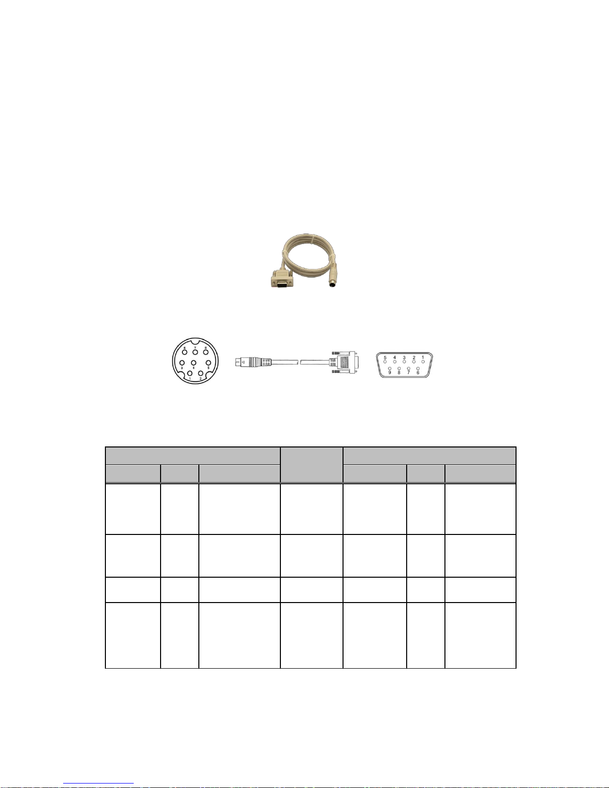
2.2. RS232
It is able to operate the OSD menu same as RC-02 by the RS232 communication.
It is also able to change the function settings or acquire the current setting without displaying
the OSD menu. See the “5.RS232 Command List” for the corresponding command.
Connect the CB-03 to the REMOTE terminal on the rear of the camera and the control
equipment such as a PC.
*CB-03 REMOTE terminal side: mini-din 8pin connector (male)
Control equipment side: D-Sub 9pin connector (female)
Figure 2. CB-03 (Serial Communication Cable)
Figure 3. Pin Number of the CB-03 (Internal wiring)
Table 1. Internal connection of the CB-03
Mini-Din 8pin (male)
Internal
Connection
D-sub 9pin (female)
Pin No.
Name
Description
Pin No.
Name
Description
3
TXD
Send from camera
Connect
2
RXD
Receive by control
equipment
(out)
(in)
5
RXD
Receive by camera
Connect
3
TXD
Send from control
equipment
(in)
(out)
4
GND
Ground
Connect
5
GND
Ground
1, 2, 6, 7, 8
NC
Unused
(For remote control
bouton)
Non-
Connect
1, 4, 6, 7, 8, 9
NC
Unused *
*Short the 7pin (RTS) and 8pin (CTS) on the control equipment side as needed.
(Disable the hardware flow control)
8
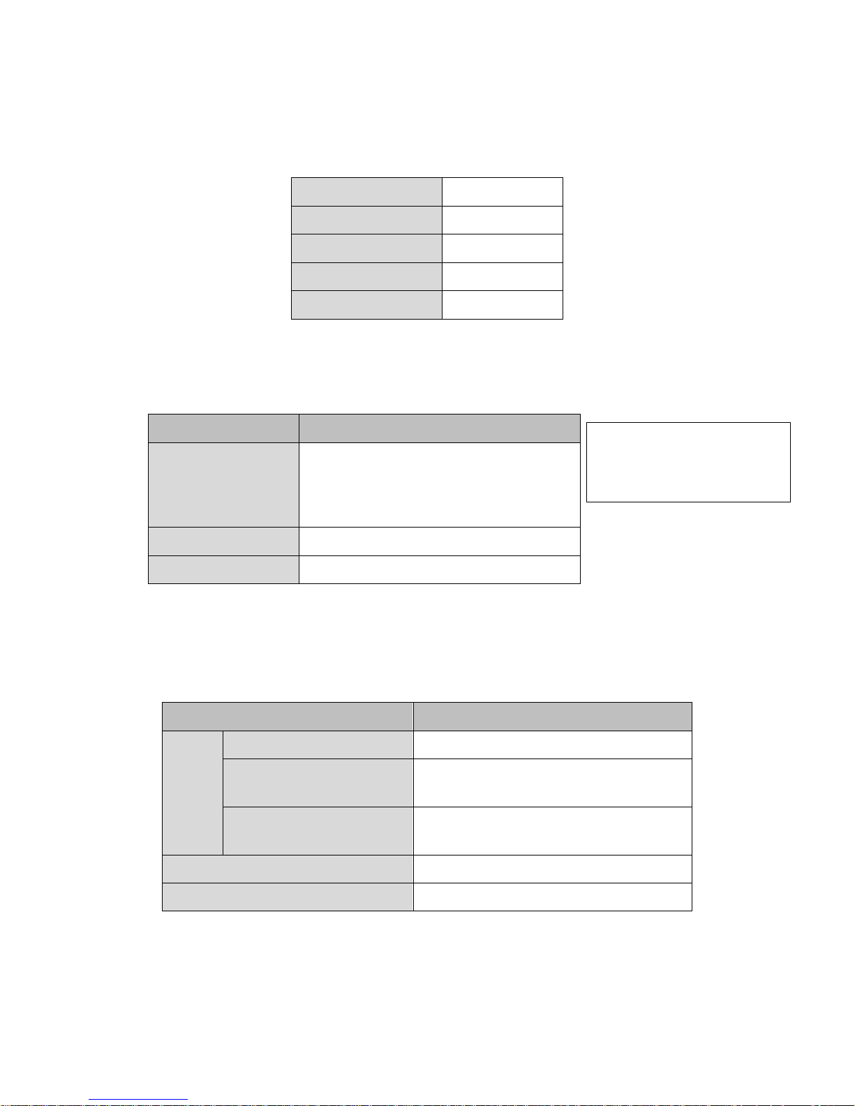
Table 2. The RS232 Communication Specifications
Communication Speed
9600bps
Data Length
8bits
Parity
None
Stop Bit
1
Flow Control
None
WAT-2200Mk-2 is designed for the following camera operation by the
VISCA/Pelco-D/Pelco-P protocol.
Table 3. Corresponding Operation to Each Protocol
Protocol
Corresponding Operation
VISCA
Change settings*, Acquire settings*,
Restore factory default,
Operate OSD menu
Pelco-D
Operate OSD menu, Change settings (flip video)
Pelco-P
Operate OSD menu, Change settings (flip video)
The camera sends the following response command when it receives the command
corresponding to each protocol.
Table 4. Response Command for Each Protocol
Protocol
Response Command
VISCA
Complete changing settings
0x90, 0x41, 0xFF, 0x90, 0x51, 0xFF
Complete acquiring settings,
Return set value
(See "response for inquiry command" on
5.RS232 command list)
Error
(Wrong part on commands)
0x90, 0x60, 0x02, 0xFF
Pelco-D
0xFF, 0x01, 0x00, 0x01
Pelco-P
0xA0, 0x01, 0x00, 0xA1
*Send multiple commands continuously from the control equipment after the camera returned the response command.
*Not correspond to all of the OSD item.
See the “5.RS232 Command List” for
the corresponding command.
9
2.3. OSD Menu Operations
All of the camera function can be set by the OSD (On Screen Display) menu.
Set the function through the OSD menu operation by the following procedure.
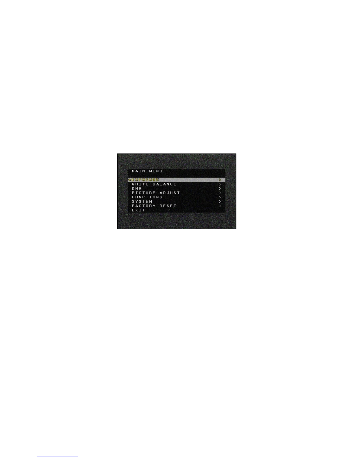
[Open / Close OSD menu]
Press the “ENTER” while the OSD menu is not displayed, or send the "OSD Open"/"OSD
On" command of the RS232, then the OSD menu (MAIN MENU) will be opened. To close
the OSD menu, move the cursor to the "EXIT" and press “ENTER” (send “ENTER”
command).
Figure 4. MAIN MENU is opened
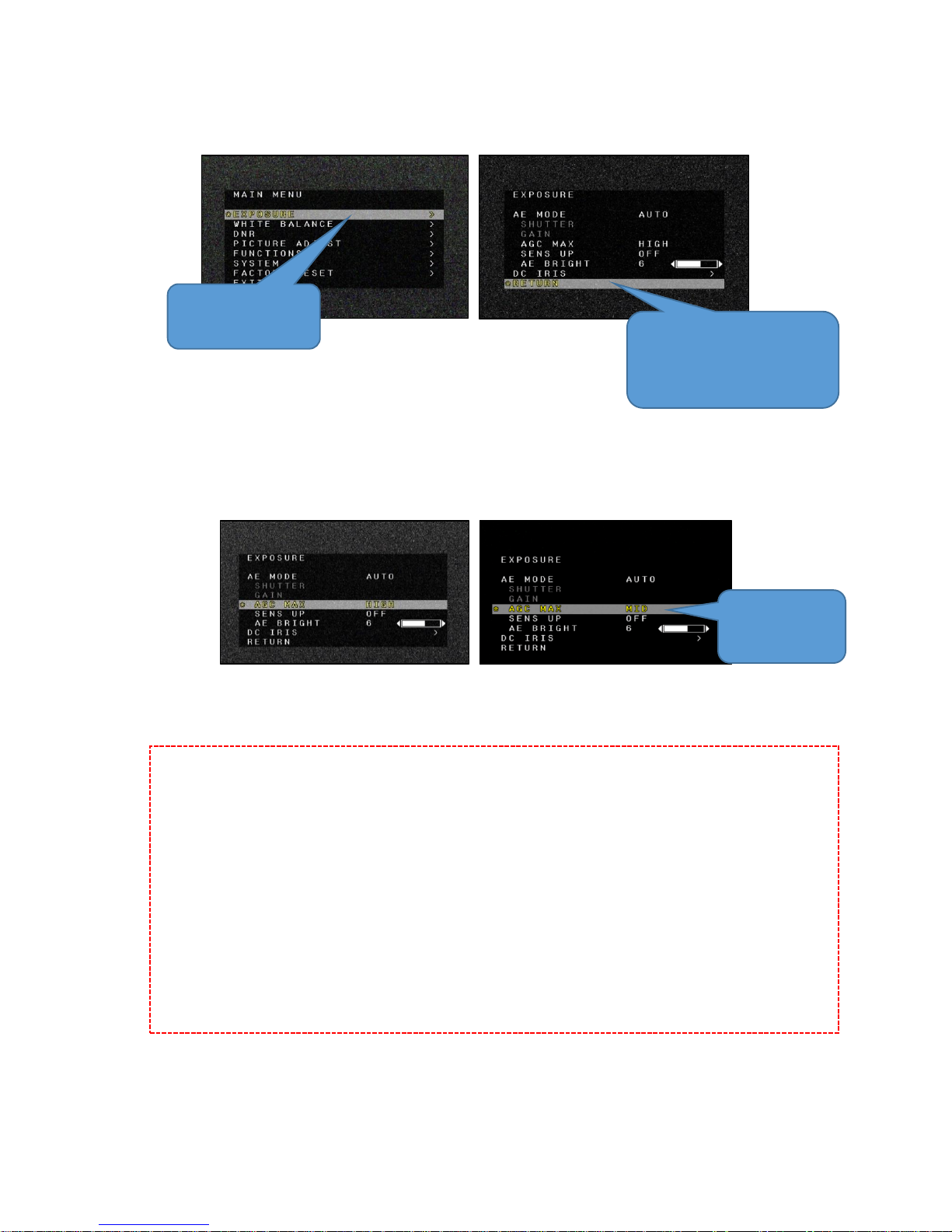
[Shift to Each Setting Menu]
Use the “UP/DOWN” on the RC-02 (“Up/Down” command of the RS232) to move the
cursor to select each OSD menu item, and press “ENTER” (send “ENTER” command) to
open each function setting menu. In the each function setting menu, to go back to the
previous menu, move the cursor to the "RETURN", and press “ENTER”.
10
Figure 5. Shift to Each Setting Menu
[Change Settings]
Use the “UP/DOWN” on the RC-02 (“Up/Down” command of the RS232) to move the
cursor to select each OSD menu item, and press ”LEFT/RIGHT” (“Left/Right” command of
the RS232) to change the setting of the item that the cursor is matched.
Figure 6. Change Settings
Precautions *Save behavior of settings
The set value is saved immediately on this camera as soon as the settings are changed
by the OSD. The settings retains even when the power of the camera is turned off.
(*Excluding the DZOOM and function not supported to be saved.)
*To retain the DZOOM function, operate the OSD/RS232 (DZOOM SAVE).
*The function not supported to be saved is below. See the “3. Description of Each Function”
for the detail of the function.
PICTURE ADJUST => DISP. FUNCTION => FREEZE
FUNCTIONS => WDR => FRAME VIEW SEL
Press “ENTER” to open
the setting menu
To go back to the previous menu,
move the cursor to the "RETURN",
and press “ENTER”
Change settings
by “LEFT/RIGHT”

11
3. Functions
Set each function by the OSD menu. Part of the function can be set by the RS232 without
displaying OSD menu. See the “5.RS232 Command List”.
3.1. EXPOSURE
3.1.1. AE MODE
Set control method of shutter, slow shutter, gain and DC iris lens.
Default: AUTO
AUTO
Automatically control the shutter speed (including SENS UP), gain and DC iris lens in
accordance with the brightness of the subject.
When a bright subject is imaged, lower the brightness to the target value by the shutter
speed and DC iris lens.
When a dark subject is imaged, heighten the brightness to the target value by the gain and
slow shutter.
The max. and min. of the shutter speed is changed in accordance with the “OUTPUT
FORMAT” setting (Table 5). The longer max. shutter speed, the higher sensitivity for the
subject in the dark, but the video resolution will be lowered.
See “3.1.7” for the DC iris lens and “3.1.5” for the slow shutter.
Figure 7. AE = AUTO Behavior (When slow shutter x2 or more, DC IRIS MODE = AUTO)
Dark
Bright
Brightness of
the subject
Slow-shutter
(SENS UP)
Gain
DC-iris
Shutter
12
Table 5. The Max. and Min. the Shutter Speed of Each OUTPUT FORMAT
OUTPUT FORMAT
Max. & Min. of the Shutter Speed (sec.)
(AE MODE=AUTO)
1080p60,1080p59,1080i60,1080i59,
720p60,720p59
1/60 - 1/10000
1080p50,1080i50,720p50
1/50 - 1/10000
1080p30,1080p29
1/30 - 1/10000
1080p25,1080p24
1/25 - 1/10000
SHUT FIX
Gain automatically controls the brightness of the subject but the shutter speed is fixed.
MANUAL
The shutter speed (including SENS UP) and gain is fixed.
3.1.2. SHUTTER
Set the shutter speed while the AE MODE is SHUT FIX or MANUAL. The configurable
shutter speed is changed in accordance with the “OUTPUT FORMAT” (Table 6).
Table 6. The Configurable Shutter Speed for Each OUTPUT FORMAT
OUTPUT FORMAT
Configurable Shutter Speed (sec.)
(AE MODE=SHUT FIX/MANUAL)
1080p60,1080p59,1080i60,1080i59,
720p60,720p59
1/60, 1/120, 1/180, 1/240,
1/300, 1/500, 1/1000, 1/2000,
1/5000, 1/10000
1080p50,1080i50,720p50
1/50, 1/100, 1/150, 1/200,
1/250, 1/500, 1/1000, 1/2000,
1/5000, 1/10000
1080p30,1080p29
1/30, 1/60, 1/120, 1/180,
1/240, 1/300, 1/500, 1/1000,
1/2000, 1/5000, 1/10000
1080p25,1080p24
1/25, 1/50, 1/100, 1/150,
1/200, 1/250, 1/500, 1/1000,
1/2000, 1/5000, 1/10000

13
3.1.3. GAIN
Set the gain while the AE MODE is MANUAL.
The configurable gain is 0, 5, 10, 15, 20, 25, 30, 35, 40, 45, 50, 55, 60, 65 and 72[dB].
3.1.4. AGC MAX
Set the max. value of gain while the AE MODE is AUTO or SHUT FIX.
Selectable from OFF, LOW, MID and HIGH.
AGC MAX = LOW AGC MAX = MID AGC MAX = HIGH
Figure 8. AGC MAX
The max. value of gain is 0dB (OFF), 36dB (LOW), 50dB (MID), 72dB (HIGH).
Default: HIGH
3.1.5. SENS UP
Set the long exposure (slow shutter). The sensitivity will be higher due to extending the
max. exposure time to 1 frame/field, but the video resolution will be lowered. The slow
shutter is set as a multiple of the min. value (the slowest value) of the shutter speed.
The configurable value is OFF, x2, x3, x4, x5, x6, x7, x8, x9, x10, x12 and x15.
Default: OFF
While the “AE MODE” is “AUTO”, the slow shutter (SENS UP) works when it is set as x2 or
more. When the subject is dark until gain reaches the max. value, the slow shutter will start
to work. While the “AE MODE” is “MANUAL”, the slow shutter will be fixed with the selected
setting value of the slow shutter.
14
3.1.6. AE BRIGHT
Set the target brightness while the AE MODE is AUTO or SHUT FIX.
The higher value is set, the brighter it gets when the AE is converged.
The setting value range is 0-10.
Default: 6
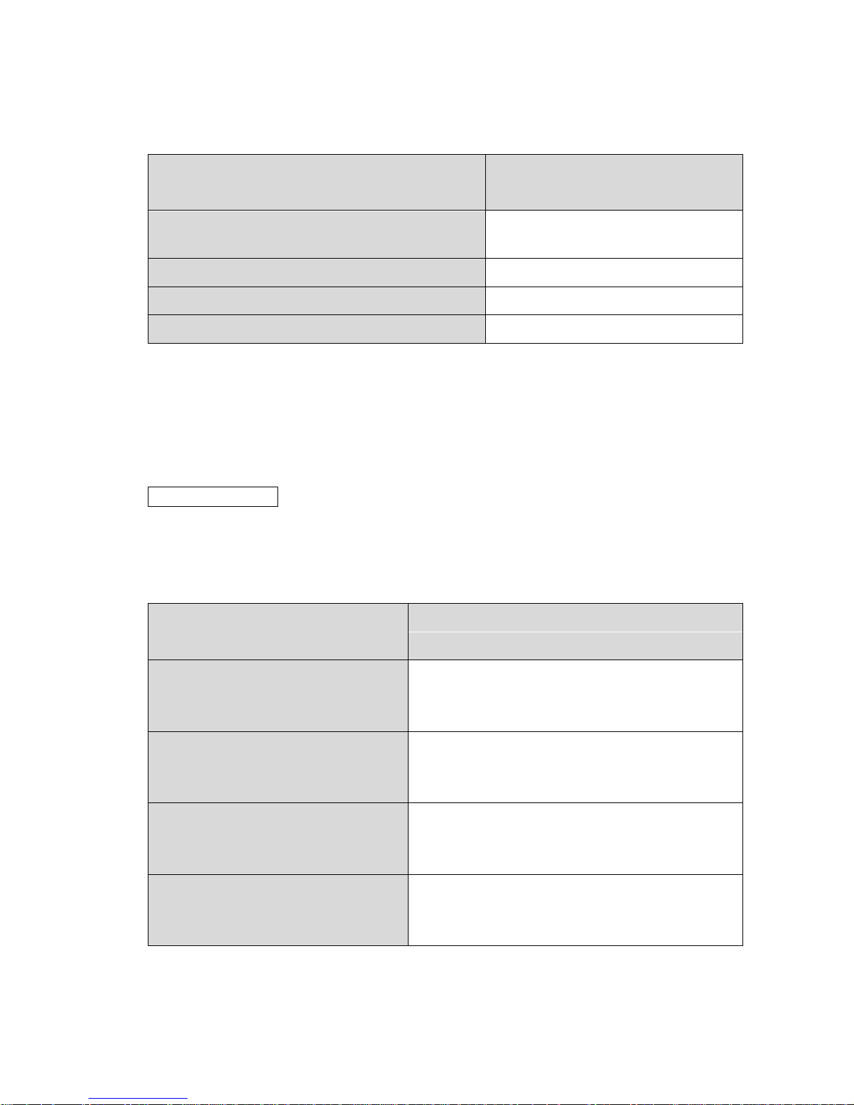
3.1.7. DC IRIS
Open the setting menu by the ENTER operation while the cursor is matched with the DC
IRIS. The following settings are configurable in the menu.
Default: MODE = OPEN, PWM OFFSET ADJ = 127, IRIS SPEED = 3
Table 7. DC IRIS
Menu Item
Value
Description
MODE
AUTO
Control the DC iris to the AE BRIGHT value.
The DC iris works while the shutter speed reaches the max.
value (when the subject is bright).
OPEN
Fully open the DC iris.
CLOSE
Fully close the DC iris.
PWM
OFFSET
ADJ
0 – 255
(127)
Set the easiness of the start moving the DC iris.
When the value is large, it starts to move soon.
Turn the power off of the camera after changing the setting
and power the camera back on.
IRIS SPEED
0 – 5 (3)
Set the speed between the start moving until convergence of
the DC iris. When the value is large, it converges quickly.
DEFAULT
-
Restore the DC iris settings to the factory default.

15
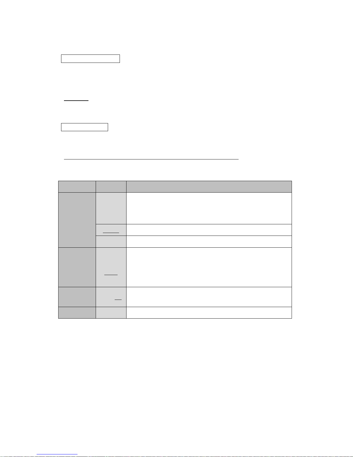
3.2. WHITE BALANCE
3.2.1. WHITE BALANCE MODE (MODE)
Set the WHITE BALANCE control mode.
Default: ATW
Table 8. WHITE BALANCE - MODE
Menu
Item
Value
Description
MODE
ATW
Automatically follow WHITE BALANCE (Approx. 2000K-15000K)
by matching the color temperature of a subject.
The range of color can follow is wider than the
INDOOR/OUTDOOR.
ONE
PUSH
Fix WHITE BALANCE at the specific color temperature.
Combined use the WHITE BALANCE convergence movement
(PUSH).
Utilize the WHITE BALANCE convergence movement (PUSH) to
complete while imaging such as a white paper.
INDOOR
WHITE BALANCE automatically follows (Approx. 4600K-7200K).
Set as easy to follow indoor light source (fluorescent light, etc.).
OUTDOOR
WHITE BALANCE automatically follows (Approx. 4600K-10000K).
Set as easy to follow outdoor light source (sunlight, etc.).
MANUAL
Manually set WHITE BALANCE
3.2.2. One Push Trigger (PUSH)
Complete the WHITE BALANCE convergence movement while the WHITE BALANCE
mode is ONE PUSH. The B and R gain value after completing PUSH operation retains even
when the power of the camera was turned off, or the WHITE BALANCE mode was changed.
When the “3.7. FACTORY RESET” is completed, the B and R gain value after completing
PUSH operation will return to default settings.
3.2.3. B-Gain (BLUE)
Set the B and R gain value while the WHITE BALANCE mode is “MANUAL”.
Lager the B gain, it will be bluer. The setting value range is 0-100.
Default: 50
16
3.2.4. R-Gain (RED)
Set the B and R gain value while the WHITE BALANCE mode is “MANUAL”.
Lager the R gain, it will be redder. The setting value range is 0-100.
Default: 50
3.2.5. White Balance Tracking Speed (SPEED)
Set the follow-speed of WHITE BALANCE while the WHITE BALANCE mode is “ATW,
INDOOR or OUTDOOR”. The larger value, the quicker speed of the follow-speed of WHITE
BALANCE when the subject color was changed. The setting value range is 0-7.
Default: 6
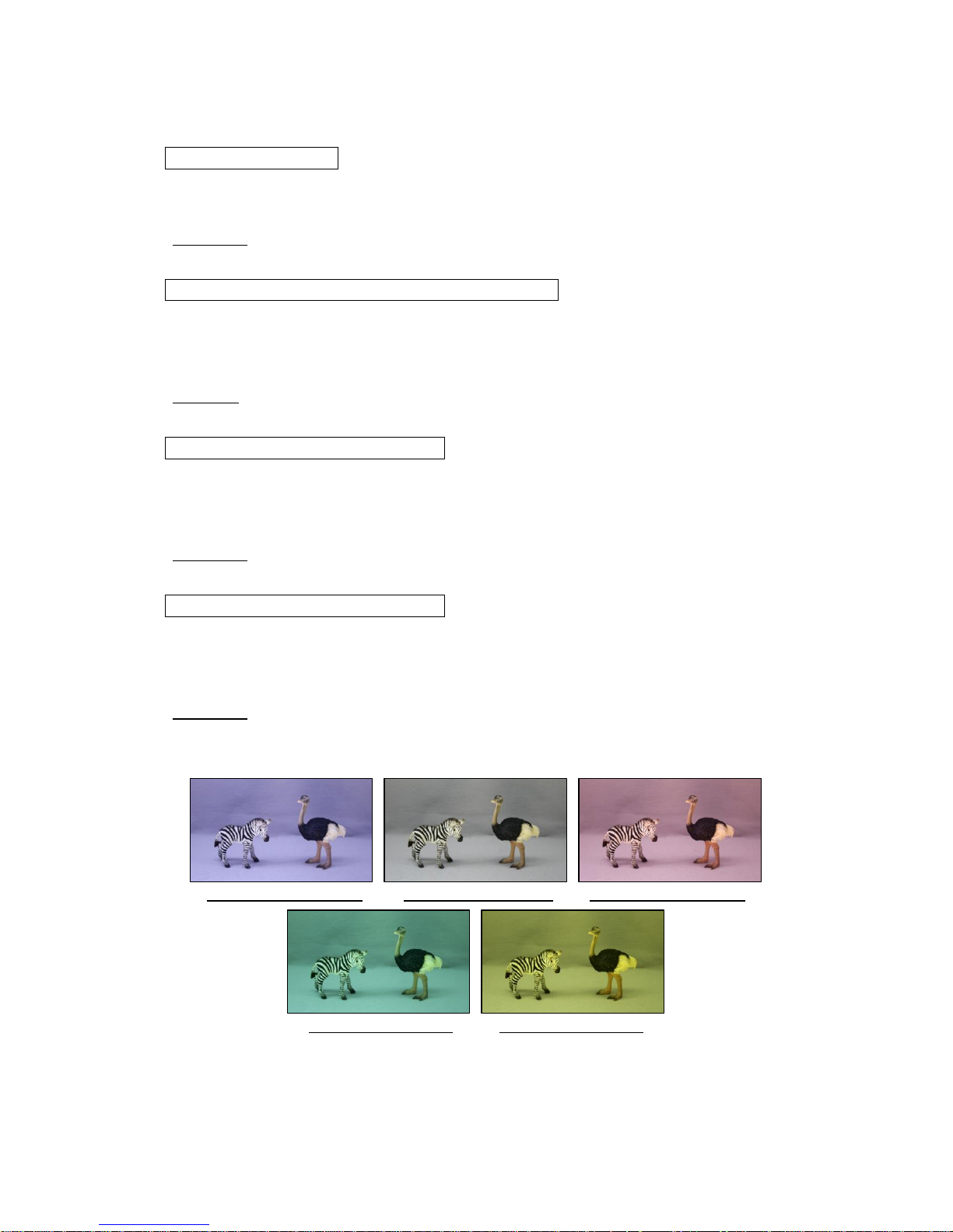
3.2.6. B-Gain Offset (OFFSET-B)
Set the offset by the B gain when WHITE BALANCE is converged while the WHITE
BALANCE mode is “ATW, INDOOR or OUTDOOR”. The larger value, when WHITE
BALANCE is converged, it will be bluer. The setting value range is 0-100.
Default: 50
3.2.7. R-Gain Offset (OFFSET-R)
Set the offset by the R gain when WHITE BALANCE is converged while the WHITE
BALANCE mode is “ATW, INDOOR or OUTDOOR”. The larger value, when WHITE
BALANCE is converged, it will be redder. The setting value range is 0-100.
Default: 50
(OFFSET-B=100, OFFSET-R=50) (OFFSET-B=50, OFFSET-R=50) (OFFSET-B=50, OFFSET-R=100)
(OFFSET-B=50, OFFSET-R=0) (OFFSET-B=0, OFFSET-R=50)
Figure 9. Change in MODE = ATW and OFFSET-B/R
17
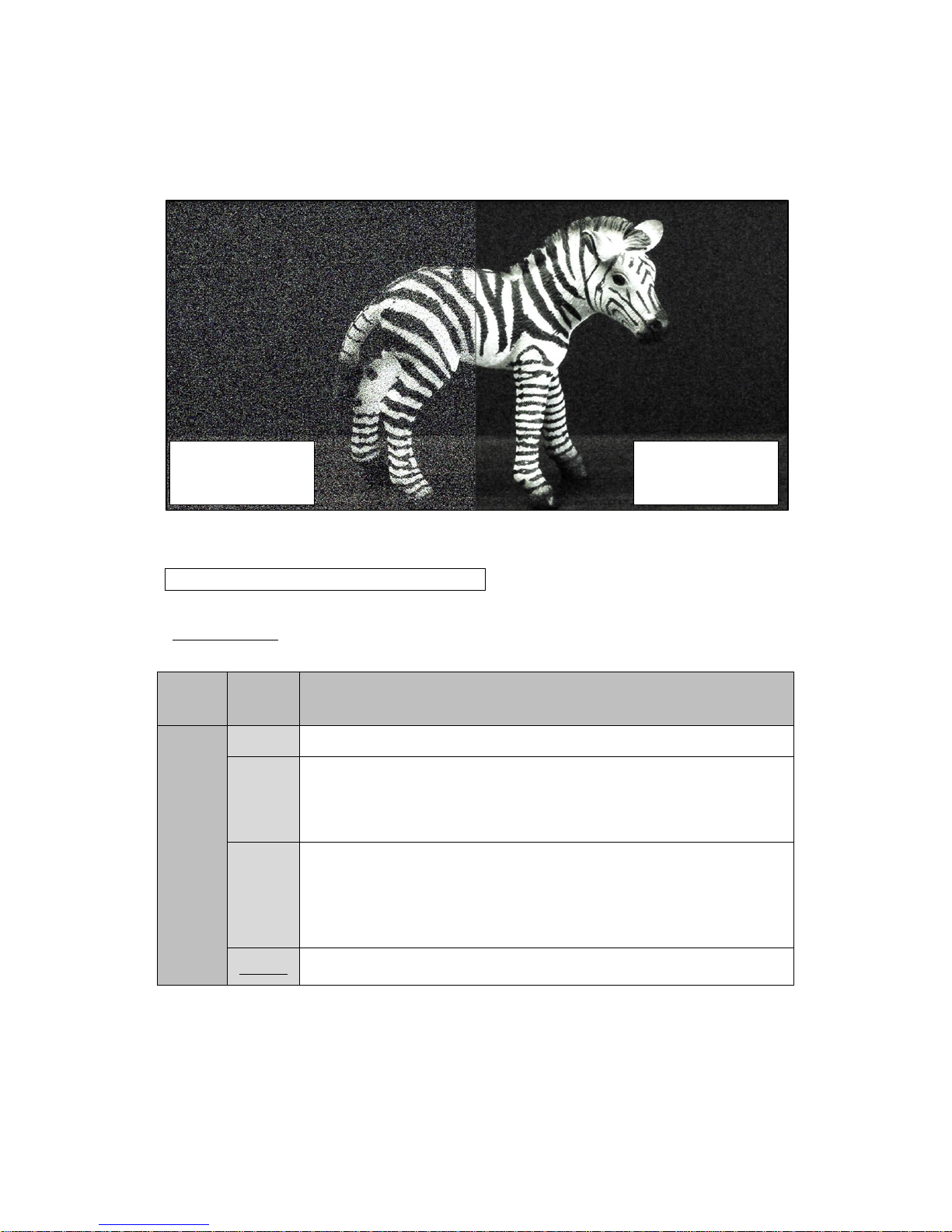
3.3. NOISE REDUCTION
Figure 10. NOISE REDUCTION
3.3.1. Noise Reduction Mode (MODE)
Set the NR (Noise Reduction) control mode.
Default: 2D+3D
Table 9. NOISE REDUCTION - MODE
Menu
Item
Value
Description
MODE
OFF
Not operating NR control.
2D
The 2DNR works.
Reduce noise by the edge preserved smoothing.
The contour of the subject may be blurred.
3D
The 3DNR works.
Reduce noise by analyzing the differences as the noise between
consecutive frames.
The after-image may be obvious depends on a subject.
2D+3D
Control NR by combining 3DNR and 2DNR.
NOISE REDUCTION
=2D+3D
NOISE REDUCTION
=OFF

18
3.3.2. Noise Reduction Level (LEVEL)
Set the strength of NR.
Default: AUTO
Table 10. NOISE REDUCTION - LEVEL
Menu
Item
Value
Description
LEVEL
AUTO
Automatically control the strength of NR.
LOW
Set the strength of NR to LOW.
The noise increases when imaging a dark subject comparing with
HIGH/MID, but the after-image will be less.
MID
Set the strength of NR to MID.
The noise and after-image is about medium between LOW/HIGH.
HIGH
Set the strength of NR to HIGH.
The noise decreases when imaging a dark subject comparing
with LOW/MID, but the after-image will be obvious.
19
3.4. PICTURE ADJUST
3.4.1. GAMMA CORRECT
Complete the ENTER operation while the GAMMA CORRECT is ON to open the setting
menu. Default: GAMMA CORRECT = ON, GAMMA = 0.45, Y LUT EXTEND = UNIFORM
OFF (1.0)
Turn off the “GAMMA CORRECT” (γ≒1.0).
ON
Turn on “GAMMA CORRECT”.
Complete the ENTER operation to open the setting menu.
Table 11. GAMMA CORRECT
Menu
Item
Value
Description
GAMMA
OFF-BYPASS,
0.9, 0.8, 0.7, 0.6, 0.55, 0.5,
0.45, 0.4
Set GAMMA CORRECT. γ≒1.0 is set by selecting
OFF-BYPASS same as GAMMA CORRECT=OFF.
Y LUT
EXTEND
UNIFORM
Uniformly correct the dark and bright part of the subject.
EXTEND-F2C
Bright correction except on the bright part on the subject.
(GAMMA = OFF-BYPASS, Y LUT EXTEND = UNIFORM) (GAMMA = 0.45, Y LUT EXTEND = UNIFORM)
(GAMMA = 0.45, Y LUT EXTEND = EXTEND-F2C)
Figure 11. GAMMA / Y LUT EXTEND

20
3.4.2. CONTRAST
Adjust the contrast difference and color density difference of the image.
The setting value range is 0-20. Default: 11
3.4.3. BRIGHTNESS
Adjust the brightness of the image.
The setting value range is 0-20. Default: 11
3.4.4. SATURATION
Adjust the saturation of the image.
The setting value range is 0-20. Default: 10
3.4.5. HUE
Adjust the hue of the image.
The setting value range is 0-20. Default: 10
3.4.6. EDGE
Adjust the contour emphasizing level.
The setting value range is 0-20. Default: 5

21
3.4.7. AUTO SATURATE
Control the saturation while the illumination of the subject is low. Default: MID
Table 12. AUTO SATURATE
Menu
Item
Value
Description
AUTO
SATURATE
OFF
Retain the saturation even while the illumination of the subject
is low. The chroma noise may be obvious, and the white
balance may be shifted from the edge.
LOW
Set the control level of the saturation while the illumination of
the subject is low. *The color of MASK/LINE becomes thin
during low illuminance while PRIVACY MASK and/or CROSS
LINE is displayed.
MID
HIGH
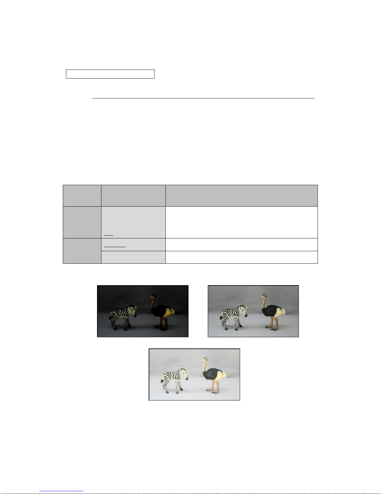
AUTO SATURATE = OFF
AUTO SATURATE = MID
Figure 12. AUTO SATURATE (illuminance of the subject = Approx. 0.1lx, AGC = HIGH)

22
3.4.8. AUTO EDGE
Weaken the contour emphasizing during low illuminance.
Default: OFF
Table 13. AUTO EDGE
Menu
Item
Value
Description
AUTO
EDGE
OFF
Retain the saturation even while the illumination of the
subject is low.
ON
Weaken the contour emphasizing during low illuminance.
The noise becomes slightly less but the contour of the
subject may become blurred.
AUTO EDGE = OFF
AUTO EDGE = ON
Figure 13. AUTO EDGE

23
3.4.9. DISPLAY FUNCTION
Open the setting menu by the ENTER operation while the cursor is matched with
“DISP.FUNCTION”. Default: FREEZE = OFF, MIRROR = OFF, IMAGE EFFECT = OFF
Table 14. DISPLAY FUNCTION
Menu
Item
Value
Description
FREEZE
OFF
Turn off FREEZE.
ON
Turn on FREEZE.
MIRROR
OFF
Turn off MIRROR.
MIRROR
Invert to right and left of the image.
V-FLIP
Invert to up and down of the image.
BOTH(H/V)
Invert to up, down, right and left of the image.
IMAGE
EFFECT
OFF
Turn off IMAGE EFFECT.
NEGATIVE
The negative-positive reversal on the contrast and
color of the image.
GREY
Make the image to achromatic color.
REDDISH-1 - 4
Make the image to red monochrome.
Color density range: 1-4
BLUISH-1 - 4
Make the image to blue monochrome.
Color density range: 1-4
GREENISH-1 - 4
Make the image to green monochrome.
Color density range: 1-4
3.4.10. Reset Picture Adjust (DEFAULT)
PICTURE ADJUST: Restore the settings in the menu to factory default.

24
3.5. FUNCTIONS
3.5.1. Digital Zoom (DZOOM)
Display the partly enlarged image.
Enlarged view by zoom and movable horizontally and vertically by pan and tilt.
Default: OFF
OFF
Turn off the “DZOOM” (1 time).
Note that the PTZ (Pan, Tilt, and Zoom) settings turn back to the original setting when
DZOOM was turned OFF without DZOOM SAVE after the setting of the position of Pan/Tilt
and ZOOM RATIO.
ON
Turn on the “DZOOM and PAN/TILT”.
The setting which is saved as DZOOM SAVE after the setting of the position of PAN/TILT
and ZOOM RATIO will be read.
Cannot use together the “DZOOM” and “DIS”.
Open the setting menu by the ENTER operation.
The following settings are available in the menu.
⚫ ZOOM CONTROL
Set the position of PAN/TILT and zoom magnification.
The setting range of DZOOM RATIO is below.
・x1.00 - x6.00 (Output Format = 1080p/1080i)
・x1.00 - x7.11 (Output Format = 720p)
The setting range of PAN/TILT is 0x00 – 0xF0. The PAN/TILT setting value is not
displayed. However, it can be read with the RS232 communication.
(See the “5.RS232 Command List”.)
(DZOOM = OFF) (DZOOM = ON, ZOOM = x3.00, PAN =0x2B, TILT =0x86)
Figure 14. DZOOM

25
[Setting Method of OSD]
-Set digital ZOOM RATIO: Operate LEFT/RIGHT while the cursor is on RATIO
*Press “ENTER” to move the cursor to the “POSITION”.
Figure 15. ZOOM
- Set the position of PAN/TILT:
Operate UP/DOWN/LEFT/RIGHT while the cursor is on POSITION
*Press “ENTER” to move the cursor to the “RETURN”. Press “ENTER” to return to the
previous screen while the cursor is on to the “RETURN”.
Figure 16. PAN/TILT
[Setting Method of RS232]
(See the “5.RS232 Command List” for the communication commands.)
-Send the command turning DZOOM=ON first.
- Specify the ZOOM RATIO by the ZOOM command.
ZOOM command = 0x81, 0x01, 0x04, 0x46, 0x00, 0x00, 0x0p, 0x0q, 0xFF
*See “Table 15” for the interrelationship between the ZOOM command setting value and
ZOOM RATIO.
- Specify the position of PAN/TILT by the PAN, TILT position command.
-The PAN/TILT position moves from the current position by sending PAN-Left, PAN-Right,
TILT-Up, TILT-Down commands.
ZOOM
ENTER
PAN/TILT
ENTER

26
Table 15. RS232 – ZOOM Commands 0xpq and ZOOM RATIO
*Coupling the low-order 4bit of 0x0p/0x0q to describe 0xpq.
0xpq
Zoom ratio
(in ZOOM command)
Output Format
1080p/1080i
720p
0x00 - 0x03
x1.00
x1.00
0x04
x1.01
x1.01
0x05 - 0x08
x1.03
x1.03
0x09 - 0x0C
x1.05
x1.05
0x0D - 0x11
x1.07
x1.07
0x12 - 0x15
x1.09
x1.09
0x16 - 0x19
x1.11
x1.11
0x1A - 0x1D
x1.13
x1.13
0x1E - 0x22
x1.15
x1.15
0x23 - 0x26
x1.17
x1.18
0x27 - 0x2A
x1.20
x1.20
0x2B - 0x2E
x1.22
x1.23
0x2F - 0x33
x1.25
x1.25
0x34 - 0x37
x1.27
x1.28
0x38 - 0x3B
x1.30
x1.31
0x3C - 0x3F
x1.33
x1.34
0x40 - 0x44
x1.36
x1.37
0x45 - 0x48
x1.39
x1.41
0x49 - 0x4C
x1.42
x1.44
0x4D - 0x50
x1.46
x1.48
0x51 - 0x55
x1.50
x1.52
0x56 - 0x59
x1.53
x1.56
0x5A - 0x5D
x1.57
x1.60
0x5E - 0x61
x1.62
x1.65
0x62 - 0x66
x1.66
x1.70
0x67 - 0x6A
x1.71
x1.75
0x6B - 0x6E
x1.76
x1.80
0x6F - 0x73
x1.81
x1.86
0x74 - 0x77
x1.87
x1.92
0x78 - 0x7B
x1.93
x1.99
0x7C - 0x7F
x2.00
x2.06
0x80 - 0x84
x2.06
x2.14
0x85 - 0x88
x2.14
x2.22
0x89 - 0x8C
x2.22
x2.31
0x8D - 0x90
x2.30
x2.40
0x91 - 0x95
x2.40
x2.50
0x96 - 0x99
x2.50
x2.62
0x9A - 0x9D
x2.60
x2.74
0x9E - 0xA1
x2.72
x2.88
0xA2 - 0xA6
x2.85
x3.03
0xA7 - 0xAA
x3.00
x3.20
0xAB - 0xAE
x3.15
x3.38
0xAF - 0xB2
x3.33
x3.59
0xB3 - 0xB7
x3.52
x3.83
0xB8 - 0xBB
x3.75
x4.10
0xBC - 0xBF
x4.00
x4.41
0xC0 - 0xC3
x4.28
x4.77
0xC4 - 0xC8
x4.61
x5.20
0xC9 - 0xCC
x5.00
x5.71
0xCD - 0xD0
x5.45
x6.33
0xD1 - 0xD5
x6.00
x7.11

27
⚫ PIP (Picture in Picture)
Partly display the image which is DZOOM=OFF on the screen. Default: OFF
The blue-colored box of the displayed part of PIP synchronizes with the range of PTZ.
*When PIP is ON, the CVBS (NTSC/PAL) output does not display correctly and is not a failure.
Figure 17. DZOOM (PIP=ON)
⚫ PIP SIZE
Set the size of PIP display.
Configurable size: 1/4, 1/9, 1/16, 1/25 Default: 1/9
⚫ PIP POSITION
Set the position of PIP.
-PIP position setting: Operate UP/DOWN/LEFT/RIGHT while the cursor is on “POSITION”.
*Press “ENTER” to move the cursor to the “RETURN”. Press “ENTER” to return to the
previous screen while the cursor is on to the “RETURN”.
Figure 18. PIP POSITION
PIP POSITON
ENTER

28
⚫ DZOOM SAVE
Save DZOOM setting to the camera.
The setting of the position of PAN/TILT and ZOOM RATIO is while the DZOOM ON (*).
*Excluding the PIP settings. The PIP settings were saved when PIP, PIP SIZE and PIP
POSITION were operated.
⚫ DEFAULT
Initialize all of the PAN/TILT, ZOOM RATIO and PIP settings.
Note that the result by DZOOM SAVE will be deleted.

29
3.5.2. DEFOG
Correct by improving visibility of the image when the contrast becomes low by foggy or
poor weather conditions. Default: OFF
OFF
Turn off the “DEFOG”.
ON
Enable the “DEFOG (FIX)”. Open the setting menu by the ENTER operation.
Table 16. DEFOG (ON)
Menu
Item
Value
Description
STRENGTH
0 – 16(8)
Set the strength of “DEFOG (FIX)”.
AUTO
Enable the “DEFOG (AUTO)”. Control DEFOG in accordance with the subject situation.
Open the setting menu by the ENTER operation.
Table 17. DEFOG (AUTO)
Menu
Item
Value
Description
THRESHOLD
0 - 3(0)
Set the threshold of “DEFOG (AUTO)”.
0=correct the most, 3=correct the least
AUTO LEVEL
HIGH
Set the strength of DEFOG (AUTO).
MID
LOW

30
3.5.3. DWDR
Correct the contrast of the subject by the histogram equalization. Default: OFF
OFF
Turn off the “DWDR”.
ON
Enable the “DWDR (FIX)”.
Correct the contrast of the subject by the histogram equalization on the bright part.
Open the setting menu by the ENTER operation.
Table 18. DWDR (ON)
Menu
Item
Value
Description
STRENGTH
0 – 16(8)
Bright correction on the dark part.
SATURATION
0 – 16(0)
Darken the bright part to make less difference with the dark part.
LOCAL RATIO
0 – 16(0)
Reduce the difference of the medium part of the contrast.
AUTO
Enable the “DWDR (AUTO)”.
Automatically control the DWDR in accordance with the subject situation.
Open the setting menu by the ENTER operation.
Table 19. DWDR (AUTO)
Menu
Item
Value
Description
SAT. SYNC
OFF
Turn off the control for lowering the brightness of the bright part.
ON
Control for lowering the brightness of the bright part.
AUTO LEVEL
HIGH
Set the strength of “DWDR (AUTO)”.
MID
LOW

31
3.5.4. MOTION DETECT
Detect the motion in the image.
Default: OFF
Figure 19. MOTION DETECTION
OFF
Turn off the “MOTION DETECT”.
ON
Turn on the “MOTION DETECT”. The detected part will be displayed in red.
Open the setting menu by the ENTER operation.
⚫ AREA
Set the MOTION DETECT area for the detail setting.
Select from AREA1-4.
⚫ AREA ENABLE
Switch the MOTION DETECT ON/OFF of the selected area.
Default: ON
⚫ AREA DISPLAY
Switch the frame display ON/OFF of the selected area.

32
⚫ SIZE/POSITION
Adjust the selected area size and position.
- MOTION DETECT area position setting: Operate UP/DOWN/LEFT/RIGHT while the
cursor is on the “POSITION”.
*Press “ENTER” to move the cursor to the “SIZE”.
Figure 20. MD POSITION
- MOTION DETECT area size setting: Operate UP/DOWN/LEFT/RIGHT while the cursor is
on the “SIZE”.
*Press “ENTER” to move the cursor to the “RETURN”. Press “ENTER” to return to the
previous screen while the cursor is on to the “RETURN”.
Figure 21. MD SIZE
⚫ SENSITIVITY
Set the detection sensitivity of the MOTION DETECT.
The larger setting value, the easier to detect. The setting value is all in common.
The setting value range is 0-40. Default: 20
MD POSITON
ENTER
MD SIZE
ENTER

33
⚫ MOTION VIEW
Switch ON/OFF of displaying the MOTION DETECT. Default: ON
⚫ VISCA ALARM
Switch ON/OFF of the VISCA command output of the MOTION DETECT result.
Default: OFF
The MOTION DETECT result will be sent as the response command like below.
Response to the MOTION DETECT result = 0x90, 0x07, 0x04, 0x1B, 0xXX, 0xFF
The XX part shows the detected area. The low-order corresponds to the detected area,
and it becomes to 1 when detected.
Example 1: Only when the area1 was detected = 0x90, 0x07, 0x04, 0x1B, 0x01, 0xFF
Example 2: All areas (1-4) were detected= 0x90, 0x07, 0x04, 0x1B, 0x0F, 0xFF
bit of XX part
7 6 5 4 3 2 1 0 Detected area
- - - - area4
area3
area2
area1
⚫ DEFAULT
Restore the MOTION DETECT setting to the default.
3.5.5. Digital Image Stabilizer (DIS)
Reduce the horizontal and vertical blur and/or vibration of the subject.
The angle of view is changed due to the correction by zooming.
Cannot use together the “DZOOM” and “DIS”.
Default: OFF
OFF
Turn off the “DIS”.
ON
Turn on the “DIS”.

34
3.5.6. Backlight Compensation (BACKLIGHT)
Make more visible the subject with backlighting, etc.
Default: OFF
OFF
Turn off the “BAKLIGHT”. Control the exposure by the entire image information.
BLC
Match the exposure to the specified area on the image.
The dark part will be more visible when metering only the dark part with backlighting.
Open the setting menu by the ENTER operation.
Table 20. BLC
Menu
Item
Value
Description
BLC
OFF
Unable BLC.
ON
Enable BLC.
SIZE
/POSITION
-
Set the BLC area size and position.
Size setting:
Operate UP/DOWN/LEFT/RIGHT while the cursor is on “SIZE”.
Position setting:
Operate UP/DOWN/LEFT/RIGHT while the cursor is on “POSITION”.
AREA
DISPLAY
OFF
Hide the BLC area.
ON
Display the BLC area.
DEFAULT
-
Restore the BLC setting to default.
BACKLIGHT = OFF BACKLIGHT = BLC
Figure 22. BLC

35
HSBLC
Match the exposure to the specified area on the entire image except the brightest part.
Make more visible the part except the headlight while imaging the subject including high
brightness part. Open the setting menu by the ENTER operation.
Table 21. HSBLC
Menu
Item
Value
Description
AREA
DISPLAY
OFF
Hide the HSBLC area.
ON
Display the HSBLC area.
SIZE
/POSITION
-
Set the HSBLC area size and position.
Size setting:
Operate UP/DOWN/LEFT/RIGHT while the cursor is on “SIZE”.
Position setting:
Operate UP/DOWN/LEFT/RIGHT while the cursor is on “POSITION”.
LEVEL
0-20(3)
Set the threshold to recognize the high brightness part.
BLACK
MASK
OFF
Does not perform masking on the high brightness part.
ON
Apply black masks on the high bright part. The pixel of the masked
part is excluded from metering area.
DEFAULT
-
Restore the HSBLC setting to the default.
BACKLIGHT = OFF
(BACKLIGHT = HSBLC, BLACK MASK = ON) (BACKLIGHT = HSBLC, BLACK MASK = OFF)
Figure 23. HSBLC

36
3.5.7. Pixel Binning (BINNING)
Enhance sensitivity by combining the A/D value of the adjacent pixels.
The resolution of the image will be low.
Default: OFF
OFF
Turn off the “BINNING”.
ON
Turn on the “BINNING”.
(AE MODE = MANUAL, SHUTTER = 1/60s, GAIN = 0dB, BINNING = OFF)
(AE MODE = MANUAL, SHUTTER = 1/60s, GAIN = 0dB, BINNING = ON)
Figure 24. BINNING

37
3.5.8. DEFECT PIXEL COMPENSATION
Correct inconspicuously the defect pixel.
Default: ON
OFF
Turn off the “DEFECT PIXEL COMPENSATION”.
ON
Turn on the “DEFECT PIXEL COMPENSATION”.
*The subject, which is similar with a defect pixel, may be corrected when it was imaged.
In this case, turn off this setting.

38
3.5.9. Multiple Exposure-Type WDR (WDR)
Make more visible of the subject with a large contrast.
Synthesize one frame of the WDR image from the two frames of the long exposure and
short exposure. The detail setting of the WDR image synthesis from the setting menu.
The video resolution when WDR=ON will be lower than when WDR=OFF.
Default: OFF
WDR = OFF
FRAME VIEW SEL = SHORT FRAME VIEW SEL = LONG
WDR = ON
Figure 25. WDR

39
OFF
Turn off the “WDR”.
ON
Turn on the “WDR”. Open the setting menu by the ENTER operation.
Table 22. WDR
Menu
Item
Value
Description
FRAME
VIEW SEL
WDR ON
Display the WDR image synthesis.
LONG
Display only the long exposure image.
SHORT
Display only the short exposure image.
WDR
STRENGTH
0-29(12)
Set the strength of the WDR process.
LOCAL
CONTRAST
0-5(2)
Set the correction level of the contrast when the WDR synthesis.
WDR AE
MODE
AUTO
Automatically adjust the shutter and gain during the WDR is
working.
It works more when the contrast of the subject change largely.
The time the WDR motion convergence will be longer.
MANUAL
The shutter and gain value is fixed during the WDR is working.
The time the WDR motion convergence will be shorter.
AE BRIGHT
0-19(10)
Set the target value of the brightness when WDR AE MODE=AUTO.
GAIN
0-19(0)
Set gain when WDR AE MODE=MANUAL.
SHUTTER
0-19(19)
Set shutter when WDR AE MODE=MANUAL.
EXPOSURE
RATIO
1:32
Set the ratio of the exposure time between short and long time
exposure. Set as 1:16 to extend the short time exposure time.
1:16
DEFAULT
-
Restore the WDR settings to the default.

40
3.5.10. PRIVACY MASK
Mask arbitrary area in the image.
8 different size, position and color masks can be displayed.
Cannot use together the “PRIVACY MASK” and “CROSS LINE”.
TYPE = SQUARE
TYPE = POLYGON
Figure 26. PRIVACY MASK
Open the setting menu by the ENTER operation while the cursor is on the “PRIVACY
MASK”. The settings in the Table 23 are available in the menu.
Default: MODE = OFF

41
Table 23. PRIVACY MASK
Menu
Item
Value
Description
MODE
OFF
Turn off the “PRIVACY MASK”.
ON
Turn on the “PRIVACY MASK”.
TYPE
SQUARE
Set the mask with adjustable square size.
POLYGON
Set the mask adjustable the 4 corner coordinates.
MASK NO.
MASK 1-8
Select the mask No. of the setting to be edited.
DISPLAY
OFF
Hide the mask.
ON
Display the mask.
COLOR
BLACK,WHITE,
GREEN,BLUE,
RED,CYAN,
MAGENTA,
YELLOW,
GRAY-1 - 6
Set the mask color.
POLY
SELECT
L-TOP,
R-TOP,
L-BOTTOM,
R-BOTTOM
Select the corner to adjust the position when the
TYPE=POLYGON is set.
L-TOP=Left top , R-TOP=Right top
L-BOTTOM=Left bottom, R-BOTTOM=Right bottom
POSITION-X
0-255
[TYPE=SQUARE]
Set the horizontal position of the mask.
[TYPE=POLYGON]
Set the selected corner coordinate (H) with POLY SELECT.
POSITION-Y
0-216
[TYPE=SQUARE]
Set the vertical position of the mask.
[TYPE=POLYGON]
Set the selected corner coordinate (V) with POLY SELECT.
SIZE-X
1-60
[TYPE=SQUARE]
Set the horizontal size of the mask.
SIZE-Y
1-33
[TYPE=SQUARE]
Set the vertical size of the mask.
DEFAULT
-
Restore the “PRIVACY MASK” setting to the default.

42
3.5.11. CROSS LINE
Display vertical/horizontal line in the image. 8 lines (4 cross lines) for the total can be
displayed with the setting of thickness, position, color and vertical/horizontal of each line.
Cannot use together the “PRIVACY MASK” and “CROSS LINE”.
Open the setting menu by the ENTER operation while the cursor is on the “CROSS LINE”.
The settings in the Table 24 are available in the menu.
Default: MODE = OFF
Table 24. CROSS LINE
Menu
Item
Value
Description
MODE
OFF
Turn off the “CROSS LINE”.
ON
Turn on the “CROSS LINE”.
LINE NO.
LINE 1-8
Select the line No. of the setting to be edited.
DISPLAY
OFF
Hide the line.
ON
Display the line.
COLOR
WHITE, GREEN,
BLUE, RED, CYAN, MAGENTA,
YELLOW, GRAY-1 - 6, BLACK
Set the line color.
DIRECTION
VERTICAL
Make the line direction vertical.
HORIZONTAL
Make the line direction horizontal.
POSITION
-959 – 959
Set the line position.
WIDTH
2 - 127
Set the line width.
DEFAULT
-
Restore the “CROSS LINE” to the default.

43
The line 1 and 2 are displayed and line 3 -8 are hidden with the default when MODE = ON.
Turn on the “DISPLAY” and select line 3-8 to display 3 or more lines.
Figure 27. CROSS LINE
3.6. SYSTEM
3.6.1. S/W INFO
Display the software information.
Open the software information display menu by the ENTER operation while the cursor is on
the “S/W INFO”.
Table 25. S/W INFO
Menu
Item
Value
Description
S/W Ver
-
Display the version of the software.
S/W Date
-
Display the release date of the software.

44
3.6.2. CAM TITLE
Display letters on the right top on the screen. Default: OFF
OFF
Turn off the “CAM TITLE”.
ON
Turn on the “CAM TITLE”. Open the setting menu by the ENTER operation.
Table 26. CAM TITLE
Menu
Item
Value
Description
TITLE
A-Z, a-z,
!, “, #, $, %, &
`, (, ), *, +, ', ., /, 0-9
Set the letter to display. Max. 10 letters.
Select letters by LEFT/RIGHT, and choose the
next letter by ENTER.
TEXT
COLOR
WHITE, BLACK OP,
WHITE OP, NO COLOR,
BLACK, BLUE,
GRAY, YELLOW
Set the letter color
Figure 28. CAM TITLE

45
3.6.3. MENU COLOR
Set the OSD menu color. Open the software information display menu by the ENTER
operation while the cursor is on the “MENU COLOR”.
Default: TEXT COLOR =WHITE, TEXT (H) COLOR = YELLOW,
B/G COLOR = BLACKOP, B/G (H) COLOR = WHITE OP
Table 27. MENU COLOR
Menu
Item
Value
Description
TEXT
COLOR
WHITE, BLACK OP,
WHITE OP, NO COLOR,
BLACK, BLUE,
GRAY, YELLOW
Set the letter color of the OSD menu.
TEXT(H)
COLOR
WHITE, BLACK OP,
WHITE OP, NO COLOR,
BLACK, BLUE,
GRAY, YELLOW
Set the selected letter color of the OSD menu.
B/G
COLOR
WHITE, BLACK OP,
WHITE OP, NO COLOR,
BLACK, BLUE,
GRAY, YELLOW
Set the background color of the OSD menu.
B/G(H)
COLOR
WHITE, BLACK OP,
WHITE OP, NO COLOR,
BLACK, BLUE,
GRAY, YELLOW
Set the selected background color of the OSD menu.
3.6.4. MENU POSITION
Set the position of the OSD menu. Selectable from below. Default: DEFAULT
DEFAULT
Set the menu position to the center.
TOP-LEFT
Set the menu position to the left top.
TOP-RIGHT
Set the menu position to the right top.

46
3.6.5. OUTPUT FORMAT
Set the SDI output format from below. Default: 1080i60
1080i60
1080i59
1080i50
1080p60
1080p59
1080p50
1080p30
1080p29
1080p25
1080p24
720p60
720p59
720p50
Select output format, and select “ENTER -> YES” and complete the ENTER operation to
switch the output format.
*The 720p60, 720p59, 720p50 are output by compressing the imaged 1920 x 1080 pixel
image with the image sensor to 1280 x 720 pixel. It is same angle of view with 1080i/p
because it is not cutting-out image.
*The 1080p30, 1080p29, 1080p25, 1080p24 may not displayed due to the connecting
monitor does not support the matched vertical synchronous frequency. The specification
of the monitor shall be checked before actual usage.
*The 1080i60, 1080i59, 1080i50 are the interlacing format. Whether the monitor and SDI to
HDMI converter support the interlacing format or not shall be checked before actual usage.
*The 1080p60, 1080p59, 1080p50 are the 3G-SDI format. Whether the connecting
equipment supports the 3G-SDI format or not shall be checked before actual usage.
*Start with the arbitrary Output Format setting by the following operation. Try that when the
image is not displayed even when connecting with peripherals. The color bar will be
displayed when the camera is started. Press “ENTER” to release the color bar display.
・1080i60 -> Turn on the unit power while pressing and holding down LEFT + RIGHT
・1080p60 ->Turn on the unit power while pressing and holding down LEFT + UP + RIGHT

47
3.6.6. CVBS FORMAT
Set the CVBS output format. Default: NTSC1
NTSC1
PAL1
Output NTSC/PAL format after compressing horizontally the 1920 x 1080 pixel (aspect
ratio 16:9) imaged with an image sensor to aspect ratio 4:3.
The both ends of the viewing angle can be seen even though the image is distorted due to
the horizontal compression.
NTSC2
PAL2
Output NTSC/PAL format after cutting-out excluding the both ends 240 pixel of the 1920 x
1080 pixel imaged with an image sensor to 1440 x 1080 pixel (aspect ratio 4:3).
The image does not be distorted but the ends of the viewing angle will not be displayed.
(The 1920 x 1080 pixel before cut-out will be displayed for the SDI.)
(SDI-out, 1920x1080)
NTSC1 NTSC2
PAL1 PAL2
Figure 29. CVBS FORMAT

48
*When the PIP on the DZOOM function is on, the CVBS side image does not output
correctly and it is not a failure.
*Start with the arbitrary CVBS Format setting by the following operation. The color bar will
be displayed when the camera is started. Press “ENTER” to release the color bar display.
・NTSC1 -> Turn on the unit power while pressing and holding down RIGHT
・PAL1 -> Turn on the unit power while pressing and holding down LEFT

49
3.7. FACTORY RESET
Figure 30. FACTORY RESET
Restore the factory default by completing the ENTER operation while the cursor is on the
“YES”, and the camera restart after a specified period.

IRIS SPEED
0 - 5 (3)
DEFAULT
RETURN
-> to "DC IRIS" menu(for DC auto iris lens advanced settings)
RETURN
○DC IRIS
DC IRIS
MODE
AUTO, OPEN, CLOSE
PWM OFFSET ADJ
0 - 255 (127)
GAIN
0 - 72dB
AGC MAX
OFF, LOW, MID, HIGH
SENS UP
OFF - x15 (OFF)
AE BRIGHT
0 - 10 (6)
DC IRIS
FACTORY RESET
EXIT
○EXPOSURE
EXPOSURE
-> Exit MAIN MENU
-> to reset all settings to the factory default settings
AE MODE
AUTO, SHUT FIX, MANUAL
SHUTTER
1/25 - 1/10000s
WHITE BALANCE
DNR
-> to NOISE REDUCTION MENU(for noise reduction function advanced settings)
-> to WHITE BALANCE MENU(for White balance fuction advanced settings)
-> to EXPOSURE MENU(for Shutter speed & Gain & DC iris lens settings)
PICTURE ADJUST
FUNCTIONS
-> to FUNCTIONS MENU(for various functions advanced settings)
SYSTEM
-> to SYSTEM MENU(for system settings)
-> to PICTURE ADJUST MENU(for picture image advanced settings)
Represents a selectable mode and setting value of each menu item
Represents the title on the OSD and not a setting item
Default : in Red
○MAIN MENU
MAIN MENU
EXPOSURE
4.OSD menu tree
Legend:
Represents OSD menu item
Represents the operation by UP, DOWN and ENTER key of the remote control
Represents the operation by RIGHT, LEFT and ENTER key of the remote control
50

RETURN
DISP. FUNCTION
-> to "DISPLAY FUNCTION" menu.
DEFAULT
RETURN
○GAMMA CORRECTION OPTION
GAMMA CORRECTION OPTION
GAMMA
OFF-BYPASS, 0.9, 0.8, 0.7, 0.6, 0.55, 0.5, 0.45, 0.4
Y LUT EXTEND
UNIFORM, EXTEND-F2C
SATURATION
0 - 20 (10)
HUE
0 - 20 (10)
EDGE ENHANCE
0 - 20 (5)
AUTO SATURATE
OFF, LOW, MID, HIGH
AUTO EDGE
OFF, ON
RETURN
○PICTURE ADJUST
PICTURE ADJUST
GAMMA CORRECT
OFF(1.0), ON
-> to "GAMMA CORRECTION OPTION" menu.
CONTRAST
0 - 20 (11)
BRIGHTNESS
0 - 20 (11)
OFFSET-R
0 - 100 (50)
RETURN
○NOISE REDUCTION
NOISE REDUCTION
MODE
OFF, 2D, 3D, 2D+3D
LEVEL
AUTO, LOW, MID, HIGH
PUSH
BLUE
0 - 100 (50)
RED
0 - 100 (50)
SPEED
0 - 7 (6)
OFFSET-B
0 - 100 (50)
○WHITE BALANCE
WHITE BALANCE
MODE
ATW, ONE PUSH, INDOOR, OUTDOOR, MANUAL
51

PICTURE STYLE
OFF, STANDARD, VIVID, CLEAR, VIVID CLR, NEUTRAL
PIC CONTRAST
0 - 6 (3)
PIC SATURATION
0 - 6 (3)
PIC EDGE
0 - 6 (3)
RETURN
○DISPLAY FUNCTION
DISPLAY FUNCTION
FREEZE
OFF, ON
MIRROR
OFF, MIRROR, V-FLIP, BOTH(H/V)
IMAGE EFFECT
OFF, NEGATIVE, GREY, REDDISH-1~4, BLUISH-1~4, GREENISH-1~4
52

DEFOG SETUP
STRENGTH
0 - 16 (8)
THRESHOLD
0 - 3 (0)
AUTO LEVEL
HIGH, MID, LOW
RETURN
PIP
OFF, ON
PIP SIZE
1/4, 1/9, 1/16, 1/25
PIP POSITION
DZOOM SAVE
DEFAULT
RETURN
○DEFOG SETUP
PRIVACY MASK
-> to "PRIVACY MASK" menu.
CROSS LINE
-> to "CROSS LINE" menu.
RETURN
○D-ZOOM
D-ZOOM
ZOOM CONTROL
BINNING
OFF, ON
DFCT PIX COMP.
OFF, ON
WDR
OFF, ON
-> to "WDR" menu.
MOTION DETECT
OFF, ON
-> to "MOTION DETECT" menu.
DIS
OFF, ON
BACKLIGHT
OFF, BLC, HSBLC
-> to "BACKLIGHT - BLC"/"BACKLIGHT - HSBLC" menu.
○FUNCTIONS
FUNCTIONS
DZOOM
OFF, ON
-> to "D-ZOOM" menu.
DEFOG
OFF, ON, AUTO
-> to "DEFOG" menu.
DWDR
OFF, ON, AUTO
-> to "DWDR" menu.
53

BLACK MASK
OFF, ON
DEFAULT
RETURN
DEFAULT
RETURN
○BACKLIGHT - HSBLC
BACKLIGHT - HSBLC
AREA DISPLAY
OFF, ON
SIZE/POSITION
LEVEL
0 - 20 (3)
DEFAULT
RETURN
○BACKLIGHT - BLC
BACKLIGHT - BLC
BLC
OFF, ON
SIZE/POSITION
AREA DISPLAY
OFF, ON
AREA DISPLAY
OFF, ON
SIZE/POSITION
SENSITIVITY
0 - 40 (20)
MOTION VIEW
OFF, ON
VISCA ALARM
OFF, ON
AUTO LEVEL
HIGH, MID, LOW
RETURN
○MOTION DETECT
MOTION DETECT
AREA
AREA 1, AREA 2, AREA 3, AREA 4
AREA ENABLE
OFF, ON
DWDR SETUP
STRENGTH
0 - 16 (8)
SATURATION
0 - 16 (0)
LOCAL RATIO
0 - 16 (0)
SAT. SYNC
OFF, ON
○DWDR SETUP
54

EXPOSURE RATIO
1:32, 1:16
DEFAULT
RETURN
LOCAL CONTRAST
0 - 5 (2)
WDR AE MODE
AUTO, MANUAL
AE BRIGHT
0 - 19 (10)
GAIN
0 - 19 (0)
SHUTTER
0 - 19 (19)
○WDR
WDR
FRAME VIEW SEL
WDR ON, LONG, SHORT
WDR STRENGTH
0 - 29 (12)
55

DIRECTION
VERTICAL, HORIZONTAL
POSITION
-959 - 959
WIDTH
2 - 127
DEFAULT
RETURN
CROSS LINE
MODE
OFF, ON
LINE NO.
LINE 1~8
DISPLAY
OFF, ON
COLOR
WHITE, GREEN, BLUE, RED, CYAN, MAGENTA, YELLOW, GRAY-1~6, BLACK
POSITION-Y
0 - 216
SIZE-X
1 - 60
SIZE-Y
1 - 33
DEFAULT
RETURN
○CROSS LINE
MASK NO.
MASK 1~8
DISPLAY
OFF, ON
COLOR
BLACK, WHITE, GREEN, BLUE, RED, CYAN, MAGENTA, YELLOW, GRAY-1~6
POLY SELECT
L-TOP, R-TOP, L-BOTTOM, R-BOTTOM
POSITION-X
0 - 255
○PRIVACY MASK
PRIVACY MASK
MODE
OFF, ON
TYPE
SQUARE, POLYGON
56

TEXT COLOR
WHITE, BLACK OP, WHITE OP, NO COLOR, BLACK, BLUE, GRAY, YELLOW
TEXT(H) COLOR
WHITE, BLACK OP, WHITE OP, NO COLOR, BLACK, BLUE, GRAY, YELLOW
B/G COLOR
WHITE, BLACK OP, WHITE OP, NO COLOR, BLACK, BLUE, GRAY, YELLOW
B/G(H) COLOR
WHITE, BLACK OP, WHITE OP, NO COLOR, BLACK, BLUE, GRAY, YELLOW
RETURN
RETURN
○CAM TITLE
CAM TITLE
TITLE
TEXT COLOR
WHITE, BLACK OP, WHITE OP, NO COLOR, BLACK, BLUE, GRAY, YELLOW
RETURN
○MENU COLOR
MENU COLOR
OUTPUT FORMAT
1080i60, 1080i59, 1080i50, 1080p60, 1080p59, 1080p50, 1080p30, 1080p29, 1080p25, 1080p24, 720p60, 720p59, 720p50
CVBS FORMAT
NTSC1, PAL1, NTSC2, PAL2
RETURN
○S/W INFO
S/W INFO
S/W Ver
S/W Date
SYSTEM
S/W INFO
-> to "S/W INFO" menu.
CAM TITLE
OFF, ON
MENU COLOR
-> to "MENU COLOR" menu.
MENU POSITION
DEFAULT, TOP-LEFT, TOP-RIGHT
-> to "CAM TITLE" menu.
○SYSTEM
57

○FACTORY RESET
FACTORY RESET ?
NO
YES
58

WAT-2200Mk-2 visca command-list (1/2)
BaudRate:9600bps, Databits:8, Parity:None, Stopbits:1, Flowcontrol:none
menu1 menu2 menu3 setting/(operation) set command inquiry command response for inquiry command
AUTO 0x81, 0x01, 0x04, 0x39, 0x00, 0xFF 0x90, 0x50, 0x00, 0xFF
SHUT FIX 0x81, 0x01, 0x04, 0x39, 0x0A, 0xFF 0x90, 0x50, 0x0A, 0xFF
MANUAL 0x81, 0x01, 0x04, 0x39, 0x03, 0xFF 0x90, 0x50, 0x03, 0xFF
(Up) 0x81, 0x01, 0x04, 0x0A, 0x02, 0xFF (Down) 0x81, 0x01, 0x04, 0x0A, 0x03, 0xFF (Reset) 0x81, 0x01, 0x04, 0x0A, 0x00, 0xFF 1/30s, 1/25s 0x81, 0x01, 0x04, 0x4A, 0x00, 0x00, 0x00, 0x05, 0xFF 0x90, 0x50, 0x00, 0x00, 0x00, 0x05, 0xFF
1/60s, 1/50s 0x81, 0x01, 0x04, 0x4A, 0x00, 0x00, 0x00, 0x06, 0xFF 0x90, 0x50, 0x00, 0x00, 0x00, 0x06, 0xFF
1/120s, 1/100s 0x81, 0x01, 0x04, 0x4A, 0x00, 0x00, 0x00, 0x08, 0xFF 0x90, 0x50, 0x00, 0x00, 0x00, 0x08, 0xFF
1/180s, 1/150s 0x81, 0x01, 0x04, 0x4A, 0x00, 0x00, 0x00, 0x0A, 0xFF 0x90, 0x50, 0x00, 0x00, 0x00, 0x0A, 0xFF
1/300s, 1/250s 0x81, 0x01, 0x04, 0x4A, 0x00, 0x00, 0x00, 0x0B, 0xFF 0x90, 0x50, 0x00, 0x00, 0x00, 0x0B, 0xFF
1/500s 0x81, 0x01, 0x04, 0x4A, 0x00, 0x00, 0x00, 0x0D, 0xFF 0x90, 0x50, 0x00, 0x00, 0x00, 0x0D, 0xFF
1/1000s 0x81, 0x01, 0x04, 0x4A, 0x00, 0x00, 0x00, 0x0F, 0xFF 0x90, 0x50, 0x00, 0x00, 0x00, 0x0F, 0xFF
1/2000s 0x81, 0x01, 0x04, 0x4A, 0x00, 0x00, 0x00, 0x11, 0xFF 0x90, 0x50, 0x00, 0x00, 0x01, 0x01, 0xFF
1/5000s 0x81, 0x01, 0x04, 0x4A, 0x00, 0x00, 0x00, 0x13, 0xFF 0x90, 0x50, 0x00, 0x00, 0x01, 0x03, 0xFF
1/10000s 0x81, 0x01, 0x04, 0x4A, 0x00, 0x00, 0x00, 0x15, 0xFF 0x90, 0x50, 0x00, 0x00, 0x01, 0x05, 0xFF
(Up) 0x81, 0x01, 0x04, 0x0C, 0x02, 0xFF (Down) 0x81, 0x01, 0x04, 0x0C, 0x03, 0xFF (Reset) 0x81, 0x01, 0x04, 0x0C, 0x00, 0xFF 0dB 0x81, 0x01, 0x04, 0x4C, 0x00, 0x00, 0x00, 0x01, 0xFF 0x90, 0x50, 0x00, 0x00, 0x00, 0x01, 0xFF
5dB 0x81, 0x01, 0x04, 0x4C, 0x00, 0x00, 0x00, 0x02, 0xFF 0x90, 0x50, 0x00, 0x00, 0x00, 0x02, 0xFF
10dB 0x81, 0x01, 0x04, 0x4C, 0x00, 0x00, 0x00, 0x03, 0xFF 0x90, 0x50, 0x00, 0x00, 0x00, 0x03, 0xFF
15dB 0x81, 0x01, 0x04, 0x4C, 0x00, 0x00, 0x00, 0x04, 0xFF 0x90, 0x50, 0x00, 0x00, 0x00, 0x04, 0xFF
20dB 0x81, 0x01, 0x04, 0x4C, 0x00, 0x00, 0x00, 0x05, 0xFF 0x90, 0x50, 0x00, 0x00, 0x00, 0x05, 0xFF
25dB 0x81, 0x01, 0x04, 0x4C, 0x00, 0x00, 0x00, 0x06, 0xFF 0x90, 0x50, 0x00, 0x00, 0x00, 0x06, 0xFF
30dB 0x81, 0x01, 0x04, 0x4C, 0x00, 0x00, 0x00, 0x07, 0xFF 0x90, 0x50, 0x00, 0x00, 0x00, 0x07, 0xFF
35dB 0x81, 0x01, 0x04, 0x4C, 0x00, 0x00, 0x00, 0x08, 0xFF 0x90, 0x50, 0x00, 0x00, 0x00, 0x08, 0xFF
40dB 0x81, 0x01, 0x04, 0x4C, 0x00, 0x00, 0x00, 0x09, 0xFF 0x90, 0x50, 0x00, 0x00, 0x00, 0x09, 0xFF
45dB 0x81, 0x01, 0x04, 0x4C, 0x00, 0x00, 0x00, 0x0A, 0xFF 0x90, 0x50, 0x00, 0x00, 0x00, 0x0A, 0xFF
50dB 0x81, 0x01, 0x04, 0x4C, 0x00, 0x00, 0x00, 0x0B, 0xFF 0x90, 0x50, 0x00, 0x00, 0x00, 0x0B, 0xFF
55dB 0x81, 0x01, 0x04, 0x4C, 0x00, 0x00, 0x00, 0x0C, 0xFF 0x90, 0x50, 0x00, 0x00, 0x00, 0x0C, 0xFF
60dB 0x81, 0x01, 0x04, 0x4C, 0x00, 0x00, 0x00, 0x0D, 0xFF 0x90, 0x50, 0x00, 0x00, 0x00, 0x0D, 0xFF
65dB 0x81, 0x01, 0x04, 0x4C, 0x00, 0x00, 0x00, 0x0E, 0xFF 0x90, 0x50, 0x00, 0x00, 0x00, 0x0E, 0xFF
72dB 0x81, 0x01, 0x04, 0x4C, 0x00, 0x00, 0x00, 0x0F, 0xFF 0x90, 0x50, 0x00, 0x00, 0x00, 0x0F, 0xFF
OFF 0x81, 0x01, 0x04, 0x2C, 0x00, 0xFF 0x90, 0x50, 0x00, 0xFF
LOW 0x81, 0x01, 0x04, 0x2C, 0x01, 0xFF 0x90, 0x50, 0x01, 0xFF
MID 0x81, 0x01, 0x04, 0x2C, 0x02, 0xFF 0x90, 0x50, 0x02, 0xFF
HIGH 0x81, 0x01, 0x04, 0x2C, 0x03, 0xFF 0x90, 0x50, 0x03, 0xFF
OFF 0x81, 0x01, 0x04, 0x5A, 0x11, 0xFF
0x90, 0x50, 0x00, 0xFF
x2 0x81, 0x01, 0x04, 0x5A, 0x12, 0xFF
0x90, 0x50, 0x01, 0xFF
x4 0x81, 0x01, 0x04, 0x5A, 0x13, 0xFF
0x90, 0x50, 0x03, 0xFF
x6 0x81, 0x01, 0x04, 0x5A, 0x14, 0xFF
0x90, 0x50, 0x05, 0xFF
x8 0x81, 0x01, 0x04, 0x5A, 0x15, 0xFF
0x90, 0x50, 0x07, 0xFF
x10 0x81, 0x01, 0x04, 0x5A, 0x16, 0xFF
0x90, 0x50, 0x09, 0xFF
x12 0x81, 0x01, 0x04, 0x5A, 0x17, 0xFF
0x90, 0x50, 0x0A, 0xFF
x15 0x81, 0x01, 0x04, 0x5A, 0x18, 0xFF
0x90, 0x50, 0x0B, 0xFF
(Up) 0x81, 0x01, 0x04, 0x3E, 0x02, 0xFF, 0x81, 0x01, 0x04, 0x0E, 0x02, 0xFF (Down) 0x81, 0x01, 0x04, 0x3E, 0x02, 0xFF, 0x81, 0x01, 0x04, 0x0E, 0x03, 0xFF (Reset) 0x81, 0x01, 0x04, 0x3E, 0x02, 0xFF, 0x81, 0x01, 0x04, 0x0E, 0x00, 0xFF 0 0x81, 0x01, 0x04, 0x3E, 0x02, 0xFF, 0x81, 0x01, 0x04, 0x4E, 0x00, 0x00, 0x00, 0x00, 0xFF 0x90, 0x50, 0x00, 0x00, 0x00, 0x00, 0xFF
1 0x81, 0x01, 0x04, 0x3E, 0x02, 0xFF, 0x81, 0x01, 0x04, 0x4E, 0x00, 0x00, 0x00, 0x01, 0xFF 0x90, 0x50, 0x00, 0x00, 0x00, 0x01, 0xFF
2 0x81, 0x01, 0x04, 0x3E, 0x02, 0xFF, 0x81, 0x01, 0x04, 0x4E, 0x00, 0x00, 0x00, 0x02, 0xFF 0x90, 0x50, 0x00, 0x00, 0x00, 0x02, 0xFF
3 0x81, 0x01, 0x04, 0x3E, 0x02, 0xFF, 0x81, 0x01, 0x04, 0x4E, 0x00, 0x00, 0x00, 0x03, 0xFF 0x90, 0x50, 0x00, 0x00, 0x00, 0x03, 0xFF
4 0x81, 0x01, 0x04, 0x3E, 0x02, 0xFF, 0x81, 0x01, 0x04, 0x4E, 0x00, 0x00, 0x00, 0x04, 0xFF 0x90, 0x50, 0x00, 0x00, 0x00, 0x04, 0xFF
5 0x81, 0x01, 0x04, 0x3E, 0x02, 0xFF, 0x81, 0x01, 0x04, 0x4E, 0x00, 0x00, 0x00, 0x05, 0xFF 0x90, 0x50, 0x00, 0x00, 0x00, 0x05, 0xFF
6 0x81, 0x01, 0x04, 0x3E, 0x02, 0xFF, 0x81, 0x01, 0x04, 0x4E, 0x00, 0x00, 0x00, 0x06, 0xFF 0x90, 0x50, 0x00, 0x00, 0x00, 0x06, 0xFF
7 0x81, 0x01, 0x04, 0x3E, 0x02, 0xFF, 0x81, 0x01, 0x04, 0x4E, 0x00, 0x00, 0x00, 0x07, 0xFF 0x90, 0x50, 0x00, 0x00, 0x00, 0x07, 0xFF
8 0x81, 0x01, 0x04, 0x3E, 0x02, 0xFF, 0x81, 0x01, 0x04, 0x4E, 0x00, 0x00, 0x00, 0x08, 0xFF 0x90, 0x50, 0x00, 0x00, 0x00, 0x08, 0xFF
9 0x81, 0x01, 0x04, 0x3E, 0x02, 0xFF, 0x81, 0x01, 0x04, 0x4E, 0x00, 0x00, 0x00, 0x09, 0xFF 0x90, 0x50, 0x00, 0x00, 0x00, 0x09, 0xFF
10 0x81, 0x01, 0x04, 0x3E, 0x02, 0xFF, 0x81, 0x01, 0x04, 0x4E, 0x00, 0x00, 0x00, 0x0A, 0xFF 0x90, 0x50, 0x00, 0x00, 0x00, 0x0A, 0xFF
AUTO 0x81, 0x01, 0x04, 0x4B, 0x00, 0x00, 0x0F, 0x00, 0xFF 0x90, 0x50, 0x00, 0x00, 0x0F, 0x00, 0xFF
OPEN 0x81, 0x01, 0x04, 0x4B, 0x00, 0x00, 0x01, 0x01, 0xFF 0x90, 0x50, 0x00, 0x00, 0x01, 0x01, 0xFF
CLOSE 0x81, 0x01, 0x04, 0x4B, 0x00, 0x00, 0x00, 0x00, 0xFF 0x90, 0x50, 0x00, 0x00, 0x00, 0x00, 0xFF
ATW 0x81, 0x01, 0x04, 0x35, 0x00, 0xFF 0x90, 0x50, 0x00, 0xFF
ONE PUSH 0x81, 0x01, 0x04, 0x35, 0x03, 0xFF 0x90, 0x50, 0x03, 0xFF
INDOOR 0x81, 0x01, 0x04, 0x35, 0x01, 0xFF 0x90, 0x50, 0x01, 0xFF
OUTDOOR 0x81, 0x01, 0x04, 0x35, 0x02, 0xFF 0x90, 0x50, 0x02, 0xFF
MANUAL 0x81, 0x01, 0x04, 0x35, 0x05, 0xFF 0x90, 0x50, 0x05, 0xFF
PUSH 0x81, 0x01, 0x04, 0x10, 0x05, 0xFF
-
(Reset) 0x81, 0x01, 0x04, 0x04, 0x00, 0xFF (Up) 0x81, 0x01, 0x04, 0x04, 0x02, 0xFF (Down) 0x81, 0x01, 0x04, 0x04, 0x03, 0xFF (Direct) 0x81, 0x01, 0x04, 0x44, 0x00, 0x00, 0x0p, 0x0q, 0xFF 0x90, 0x50, 0x00, 0x00, 0x0p, 0x0q, 0xFF[pq=0x00~0x64]
(Reset) 0x81, 0x01, 0x04, 0x03, 0x00, 0xFF (Up) 0x81, 0x01, 0x04, 0x03, 0x02, 0xFF (Down) 0x81, 0x01, 0x04, 0x03, 0x03, 0xFF (Direct) 0x81, 0x01, 0x04, 0x43, 0x00, 0x00, 0x0p, 0x0q, 0xFF 0x90, 0x50, 0x00, 0x00, 0x0p, 0x0q, 0xFF[pq=0x00~0x64]
OFF 0x81, 0x01, 0x04, 0x53, 0x00, 0xFF 0x90, 0x50, 0x00, 0xFF
2D 0x81, 0x01, 0x04, 0x53, 0x01, 0xFF 0x90, 0x50, 0x01, 0xFF
3D 0x81, 0x01, 0x04, 0x53, 0x02, 0xFF 0x90, 0x50, 0x02, 0xFF
2D+3D 0x81, 0x01, 0x04, 0x53, 0x03, 0xFF 0x90, 0x50, 0x03, 0xFF
AUTO 0x81, 0x01, 0x04, 0x53, 0x04, 0xFF
LOW 0x81, 0x01, 0x04, 0x53, 0x05, 0xFF
MID 0x81, 0x01, 0x04, 0x53, 0x06, 0xFF
HIGH 0x81, 0x01, 0x04, 0x53, 0x07, 0xFF
RED
BLUE
LEVEL
MODE
EXPOSURE
WHITE BALANCE
DNR
0x81, 0x09, 0x04, 0x4B, 0xFF
0x81, 0x09, 0x04, 0x35, 0xFF
0x81, 0x09, 0x04, 0x44, 0xFF
0x81, 0x09, 0x04, 0x43, 0xFF
DC IRIS
GAIN
SHUTTER
AE MODE
AGC MAX
SENS UP
AE BRIGHT
MODE
MODE
0x81, 0x09, 0x04, 0x4E, 0xFF
0x81, 0x09, 0x04, 0x39, 0xFF
0x81, 0x09, 0x04, 0x4A, 0xFF
0x81, 0x09, 0x04, 0x4C, 0xFF
0x81, 0x09, 0x04, 0x2C, 0xFF
0x81, 0x09, 0xA1, 0x09, 0xFF
0x81, 0x09, 0x04, 0x53, 0xFF
-
-

WAT-2200Mk-2 visca command-list (2/2)
BaudRate:9600bps, Databits:8, Parity:None, Stopbits:1, Flowcontrol:none
menu1 menu2 menu3 setting/(operation) set command inquiry command response for inquiry command
ON 0x81, 0x01, 0x04, 0x5B, 0x01, 0xFF 0x90, 0x50, 0x01, 0xFF
OFF(1.0) 0x81, 0x01, 0x04, 0x5B, 0x00, 0xFF 0x90, 0x50, 0x00, 0xFF
OFF-BYPASS 0x81, 0x01, 0x04, 0x5B, 0x10, 0xFF
0.4 0x81, 0x01, 0x04, 0x5B, 0x18, 0xFF
0.45 0x81, 0x01, 0x04, 0x5B, 0x17, 0xFF
0.5 0x81, 0x01, 0x04, 0x5B, 0x16, 0xFF
0.55 0x81, 0x01, 0x04, 0x5B, 0x15, 0xFF
0.6 0x81, 0x01, 0x04, 0x5B, 0x14, 0xFF
0.7 0x81, 0x01, 0x04, 0x5B, 0x13, 0xFF
0.8 0x81, 0x01, 0x04, 0x5B, 0x12, 0xFF
0.9 0x81, 0x01, 0x04, 0x5B, 0x11, 0xFF
0~20 0x81, 0x01, 0x04, 0x49, 0x00, 0x00, 0x0p, 0x0q, 0xFF
0x81, 0x09, 0x04, 0x49, 0xFF
0x90, 0x50, 0x00, 0x00, 0x0p, 0x0q, 0xFF[pq=0x00~0x14]
0~20 0x81, 0x01, 0x04, 0x4F, 0x00, 0x00, 0x0p, 0x0q, 0xFF
0x81, 0x09, 0x04, 0x4F, 0xFF
0x90, 0x50, 0x00, 0x00, 0x0p, 0x0q, 0xFF[pq=0x00~0x14]
0~20 0x81, 0x01, 0x04, 0x42, 0x00, 0x00, 0x0p, 0x0q, 0xFF
0x81, 0x09, 0x04, 0x42, 0xFF
0x90, 0x50, 0x00, 0x00, 0x0p, 0x0q, 0xFF[pq=0x00~0x14]
OFF 0x81, 0x01, 0x04, 0x5F, 0x00, 0xFF 0x90, 0x50, 0x00, 0xFF
LOW 0x81, 0x01, 0x04, 0x5F, 0x01, 0xFF 0x90, 0x50, 0x01, 0xFF
MID 0x81, 0x01, 0x04, 0x5F, 0x02, 0xFF 0x90, 0x50, 0x02, 0xFF
HIGH 0x81, 0x01, 0x04, 0x5F, 0x03, 0xFF 0x90, 0x50, 0x03, 0xFF
OFF 0x81, 0x01, 0x04, 0x62, 0x03, 0xFF 0x90, 0x50, 0x03, 0xFF
ON 0x81, 0x01, 0x04, 0x62, 0x02, 0xFF 0x90, 0x50, 0x02, 0xFF
OFF 0x81, 0x01, 0x04, 0x61, 0x03, 0xFF, 0x81, 0x01, 0x04, 0x66, 0x03, 0xFF 0x90, 0x50, 0x03, 0xFF, 0x90, 0x50, 0x03, 0xFF
MIRROR 0x81, 0x01, 0x04, 0x61, 0x02, 0xFF, 0x81, 0x01, 0x04, 0x66, 0x03, 0xFF 0x90, 0x50, 0x02, 0xFF, 0x90, 0x50, 0x03, 0xFF
V-FLIP 0x81, 0x01, 0x04, 0x61, 0x03, 0xFF, 0x81, 0x01, 0x04, 0x66, 0x02, 0xFF 0x90, 0x50, 0x03, 0xFF, 0x90, 0x50, 0x02, 0xFF
BOTH(H/V) 0x81, 0x01, 0x04, 0x61, 0x02, 0xFF, 0x81, 0x01, 0x04, 0x66, 0x02, 0xFF 0x90, 0x50, 0x02, 0xFF, 0x90, 0x50, 0x02, 0xFF
OFF 0x81, 0x01, 0x04, 0x63, 0x00, 0xFF 0x90, 0x50, 0x00, 0xFF
NEGATIVE 0x81, 0x01, 0x04, 0x63, 0x02, 0xFF 0x90, 0x50, 0x01, 0xFF
GREY 0x81, 0x01, 0x04, 0x63, 0x04, 0xFF 0x90, 0x50, 0x02, 0xFF
OFF 0x81, 0x01, 0x04, 0x37, 0x03, 0x00, 0xFF 0x90, 0x50, 0x03, 0x00, 0xFF
ON 0x81, 0x01, 0x04, 0x37, 0x02, 0x11, 0xFF 0x90, 0x50, 0x02, 0x02, 0xFF
AUTO 0x81, 0x01, 0x04, 0x37, 0x02, 0x10, 0xFF 0x90, 0x50, 0x02, 0x00, 0xFF
OFF 0x81, 0x01, 0x04, 0x1B, 0x03, 0xFF 0x90, 0x50, 0x03, 0xFF
ON,Alarm-OFF 0x81, 0x01, 0x04, 0x1B, 0x04, 0xFF 0x90, 0x50, 0x04, 0xFF
ON,Alarm-ON 0x81, 0x01, 0x04, 0x1B, 0x02, 0xFF 0x90, 0x50, 0x02, 0xFF
OFF 0x81, 0x01, 0x04, 0x34, 0x03, 0xFF 0x90, 0x50, 0x03, 0xFF
ON 0x81, 0x01, 0x04, 0x34, 0x02, 0xFF 0x90, 0x50, 0x02, 0xFF
OFF 0x81, 0x01, 0x04, 0x33, 0x03, 0xFF 0x90, 0x50, 0x03, 0xFF
ON 0x81, 0x01, 0x04, 0x33, 0x02, 0xFF 0x90, 0x50, 0x02, 0xFF
OFF 0x81, 0x01, 0x04, 0x14, 0x03, 0xFF 0x90, 0x50, 0x03, 0xFF
ON 0x81, 0x01, 0x04, 0x14, 0x02, 0xFF 0x90, 0x50, 0x02, 0xFF
OFF 0x81, 0x01, 0x04, 0x3D, 0x03, 0xFF 0x90, 0x50, 0x03, 0xFF
ON 0x81, 0x01, 0x04, 0x3D, 0x02, 0xFF 0x90, 0x50, 0x02, 0xFF
OFF 0x81, 0x01, 0x04, 0x06, 0x03, 0xFF 0x90, 0x50, 0x03, 0xFF
ON 0x81, 0x01, 0x04, 0x06, 0x02, 0xFF 0x90, 0x50, 0x02, 0xFF
PAN-Left 0x81, 0x01, 0x06, 0x01, 0x00, 0x00, 0x03, 0x01, 0xFF 0x90, 0x50, 0x0p, 0x0q, 0x0r, 0x0s, 0xFF
PAN-Right 0x81, 0x01, 0x06, 0x01, 0x00, 0x00, 0x03, 0x02, 0xFF [pq=PAN=0x00~0xF0]
TILT-Up 0x81, 0x01, 0x06, 0x01, 0x00, 0x00, 0x01, 0x03, 0xFF [rs=TILT=0x00~0xF0]
TILT-Down 0x81, 0x01, 0x06, 0x01, 0x00, 0x00, 0x02, 0x03, 0xFF
PAN,TILT position 0x81, 0x01, 0x06, 0x02, 0x00, 0x00, 0x00, 0x00, 0x0m, 0x0n, 0x00, 0x00, 0x0p, 0x0q, 0xFF
ZOOM 0x81, 0x01, 0x04, 0x46, 0x00, 0x00, 0x0p, 0x0q, 0xFF 0x90, 0x50, 0x00, 0x00, 0x0D, 0x05, 0xFF
ZOOM(x1) 0x81, 0x01, 0x04, 0x46, 0x00, 0x00, 0x00, 0x00, 0xFF [pq=0x00~0xD5]
ZOOM(x2) 0x81, 0x01, 0x04, 0x46, 0x00, 0x00, 0x07, 0x0F, 0xFF
ZOOM(x3) 0x81, 0x01, 0x04, 0x46, 0x00, 0x00, 0x0A, 0x0A, 0xFF
ZOOM(x4) 0x81, 0x01, 0x04, 0x46, 0x00, 0x00, 0x0B, 0x0F, 0xFF
ZOOM(x5) 0x81, 0x01, 0x04, 0x46, 0x00, 0x00, 0x0C, 0x0C, 0xFF
ZOOM(x6) 0x81, 0x01, 0x04, 0x46, 0x00, 0x00, 0x0D, 0x05, 0xFF
DZOOM SAVE 0x81, 0x01, 0xA1, 0x04, 0x00, 0x00, 0x00, 0x01, 0xFF
-
1080i60 0x81, 0x01, 0x04, 0x24, 0x72, 0x00, 0x02, 0xFF 0x90, 0x50, 0x00, 0x02, 0xFF
1080i59 0x81, 0x01, 0x04, 0x24, 0x72, 0x00, 0x01, 0xFF 0x90, 0x50, 0x00, 0x01, 0xFF
1080i50 0x81, 0x01, 0x04, 0x24, 0x72, 0x00, 0x04, 0xFF 0x90, 0x50, 0x00, 0x04, 0xFF
1080p60 0x81, 0x01, 0x04, 0x24, 0x72, 0x01, 0x05, 0xFF 0x90, 0x50, 0x01, 0x05, 0xFF
1080p59 0x81, 0x01, 0x04, 0x24, 0x72, 0x01, 0x03, 0xFF 0x90, 0x50, 0x01, 0x03, 0xFF
1080p50 0x81, 0x01, 0x04, 0x24, 0x72, 0x01, 0x04, 0xFF 0x90, 0x50, 0x01, 0x04, 0xFF
1080p30 0x81, 0x01, 0x04, 0x24, 0x72, 0x00, 0x07, 0xFF 0x90, 0x50, 0x00, 0x07, 0xFF
1080p29 0x81, 0x01, 0x04, 0x24, 0x72, 0x00, 0x06, 0xFF 0x90, 0x50, 0x00, 0x06, 0xFF
1080p25 0x81, 0x01, 0x04, 0x24, 0x72, 0x00, 0x08, 0xFF 0x90, 0x50, 0x00, 0x08, 0xFF
720p60 0x81, 0x01, 0x04, 0x24, 0x72, 0x00, 0x0A, 0xFF 0x90, 0x50, 0x00, 0x0A, 0xFF
720p59 0x81, 0x01, 0x04, 0x24, 0x72, 0x00, 0x09, 0xFF 0x90, 0x50, 0x00, 0x09, 0xFF
720p50 0x81, 0x01, 0x04, 0x24, 0x72, 0x00, 0x0C, 0xFF 0x90, 0x50, 0x00, 0x0C, 0xFF
NTSC1 0x81, 0x01, 0x04, 0x24, 0x72, 0x00, 0x03, 0xFF 0x90, 0x50, 0x00, 0x00, 0x00, 0x00, 0xFF
PAL1 0x81, 0x01, 0x04, 0x24, 0x72, 0x00, 0x05, 0xFF 0x90, 0x50, 0x00, 0x00, 0x00, 0x01, 0xFF
FACTORY RESET
0x81, 0x01, 0xA1, 0x06, 0x00, 0x00, 0x00, 0x01, 0xFF
0x81, 0x01, 0xA1, 0x03, 0x00, 0x00, 0x00, 0x01, 0xFF
0x81, 0x01, 0xA1, 0x03, 0x00, 0x00, 0x00, 0x10, 0xFF
0x81, 0x01, 0xA1, 0x03, 0x00, 0x00, 0x00, 0x11, 0xFF
0x81, 0x01, 0xA1, 0x03, 0x00, 0x00, 0x00, 0x12, 0xFF
0x81, 0x01, 0xA1, 0x03, 0x00, 0x00, 0x00, 0x13, 0xFF
0x81, 0x01, 0xA1, 0x03, 0x00, 0x00, 0x00, 0x14, 0xFF
0x81, 0x01, 0xA1, 0x03, 0x00, 0x00, 0x00, 0x15, 0xFF
-
DIS
WDR
DZOOM
-
(OSD Open)
0x81, 0x09, 0x04, 0x06, 0xFF
0x81, 0x09, 0x04, 0x12, 0xFF
0x81, 0x09, 0x04, 0x46, 0xFF
0x81, 0x09, 0x04, 0x24, 0x72, 0xFF
0x81, 0x09, 0xA1, 0x07, 0xFF
BACK LIGHT
GAMMA
AUTO SATURATE
EDGE ENHANCE
HUE
SATURATION
DISP.FUNCTION
MIRROR
IMAGE EFFECT
FREEZE
HSBLC
BLC
DEFOG
MOTION DETECT
PICTURE ADJUST
FUNCTIONS
SYSTEM
(OSD)
(OSD Exit)
(OSD Enter)
(OSD Left)
(OSD Right)
(OSD Down)
(OSD Up)
RESTORE FACTORY SETTINGS
OUTPUT FORMAT
CVBS FORMAT
ZOOM CONTROL
GAMMA CORRECT
0x81, 0x09, 0x04, 0x37, 0xFF
0x81, 0x09, 0x04, 0x1B, 0xFF
0x81, 0x09, 0x04, 0x34, 0xFF
0x81, 0x09, 0x04, 0x33, 0xFF
0x81, 0x09, 0x04, 0x14, 0xFF
0x81, 0x09, 0x04, 0x3D, 0xFF
0x81, 0x09, 0x04, 0x63, 0xFF
-
0x81, 0x09, 0x04, 0x5F, 0xFF
0x81, 0x09, 0x04, 0x62, 0xFF
0x81, 0x09, 0x04, 0x61, 0xFF, 0x81, 0x09, 0x04, 0x66, 0xFF
-
0x81, 0x09, 0x04, 0x5B, 0xFF

WAT-2200Mk-2 pelco command-list
BaudRate:9600bps, Databits:8, Parity:None, Stopbits:1, Flowcontrol:none
type operation command response
flip(H+V) on/off 0xFF, 0x01, 0x00, 0x07, 0x00, 0x21, 0x29
OSDMenu on-off 0xFF, 0x01, 0x00, 0x07, 0x00, 0x5F, 0x67
OSDMenu Up 0xFF, 0x01, 0x00, 0x07, 0x00, 0x60, 0x68
OSDMenu Down 0xFF, 0x01, 0x00, 0x07, 0x00, 0x61, 0x69
OSDMenu Right 0xFF, 0x01, 0x00, 0x07, 0x00, 0x62, 0x6A
OSDMenu Left 0xFF, 0x01, 0x00, 0x07, 0x00, 0x63, 0x6B
OSDMenu Enter 0xFF, 0x01, 0x00, 0x07, 0x00, 0x64, 0x6C
flip(H+V) on/off 0xA0, 0x01, 0x00, 0x07, 0x00, 0x21, 0xAF, 0x28
OSDMenu on-off 0xA0, 0x01, 0x00, 0x07, 0x00, 0x5F, 0xAF, 0x56
OSDMenu Up 0xA0, 0x01, 0x00, 0x07, 0x00, 0x60, 0xAF, 0x69
OSDMenu Down 0xA0, 0x01, 0x00, 0x07, 0x00, 0x61, 0xAF, 0x68
OSDMenu Right 0xA0, 0x01, 0x00, 0x07, 0x00, 0x62, 0xAF, 0x6B
OSDMenu Left 0xA0, 0x01, 0x00, 0x07, 0x00, 0x63, 0xAF, 0x6A
OSDMenu Enter 0xA0, 0x01, 0x00, 0x07, 0x00, 0x64, 0xAF, 0x6D
pelco-d
pelco-p
0xFF, 0x01, 0x00, 0x01
0xA0, 0x01, 0x00, 0xA1
 Loading...