

Watec WAT-1100MBD Operation Manual
1/3.2“ High Sensitivity Miniature Board D/N Camera
WAT-1100MBD
Operation Manual
This operation manual covers safety, camera functions, installation and the
correct operating procedure for the WAT-1100MBD. First, we ask you to
read this operation manual thoroughly, then install and operate the
WAT-1100MBD as advised. In addition, for future reference, we also advise
safekeeping of this manual.
Please contact the distributor or dealer from which the WAT-1100MBD was
purchased, if you do not understand the installation, operation or safety
instructions laid out in this manual. Not understanding the contents of the
operation manual sufficiently may cause damage to the camera.
Guide to the Safety Symbols
The definitions of the symbols used in this operation manual are:
When you do not adhere to or take notice of the “Danger” sign,
it may lead to a serious accident such as death or injury caused
by fire or electric shock.
When you do not adhere to or take notice of the “Warning” sign,
it may cause severe damage such as a physical injury.
When you do not adhere to or take notice of the “Caution” sign,
it may incur injury and cause damage to peripheral objects in
the immediate surroundings.
Cautions for Safety
The WAT-1100MBD is designed to be used safely; however, it may lead to a
physical accident caused by fire and electric shock if not used correctly.
Therefore, please keep and read the “Cautions for safety” b elow for
protection against accidents.
Do not disassemble and/or modify the WAT-1100MBD.
Do not operate the WAT-1100MBD with wet hands.
Use a stabilized power adaptor designed for DC 5V to 12V,
with a current capacity of more than 25 0mA for the
WAT-1100MBD.
The recommended voltage is DC 5V to 12V.
Do not expose the WAT-1100MBD to wetness or high
moisture conditions.
The WAT-1100MBD is designed and approved for indoor use
only. The WAT-1100MBD is not water-resistant or waterproof. If
the location of the camera is outdoors or in an outdoor like
environment, we recommend that you use an outdoor camera
housing.
Protect the WAT-1100MBD from condensation.
Keep the WAT-1100MBD dry at all times during storage and
operation.
Should the camera not work properly, switch off the power
immediately. Then, check the camera according to the
“Problems and Trouble Shooting” section.
Avoid the striking of hard objects or dropping the
WAT-1100MBD.
The WAT-1100MBD uses high quality electrical parts and
precision components.
Do not connect any power supply directly to th e video out
terminal of the unit.
Do not connect the WAT-1100MBD with any monitor using a
video/power single transmission terminal. The WAT-1100MBD
is not designed for use with this type of equipment. We also
advise you to read the operation manual of the monitor you
plan to use before any connections are made.
Do not install the WAT-1100MBD in a position subject to
direct sunlight.
Sunlight shinning directly onto the WAT-1100MBD lens can
cause damage to the image sensor.
Select a stable place for installation of the WAT-1100MBD.
Always fix the camera securely.
See ”Mounting Holes” section.
Do not move the WAT-1100MBD with the cables connected.
Before moving the WAT-1100 MBD, always remove the video
cable and power cable from the rear of the camera first.
Avoid using the WAT-1100MBD near any strong
electromagnetic field.
After installing into main equipment, if the WAT-1100MBD is
exposed to electromagnetic waves causing the monitored
image to become distorted, we recommend the camera be
shielded by
appropriate protective casing.
Problems and Trouble Shooting
If any of the following problems occur when using the WAT-1100MBD,
An optimal picture cannot be obtained, after checking that all the cables
and connections are correctly in place.
Smoke or any unusual odor emerges from the WAT-1100MBD.
An object becomes embedded or a quantit y of liquid seeps into the
camera housing.
More than the recommended voltage or/and amperage has been
applied to the WAT-1100MBD by mistake.
Anything unusual occurring to any equipment connected to the
WAT-1100MBD.
Disconnect the camera immediately according to the following
procedures:
① Switch off the main power supply to the camera.
② Remove the power and video cables connected to the WAT-1100MBD.
③ Contact the distributor or dealer from which the WAT-1100MBD was
purchased
Contents
Using the contents figures below, check to make sure all parts are present
before use.
WAT-1100MBD
4P Cable
2P Cable
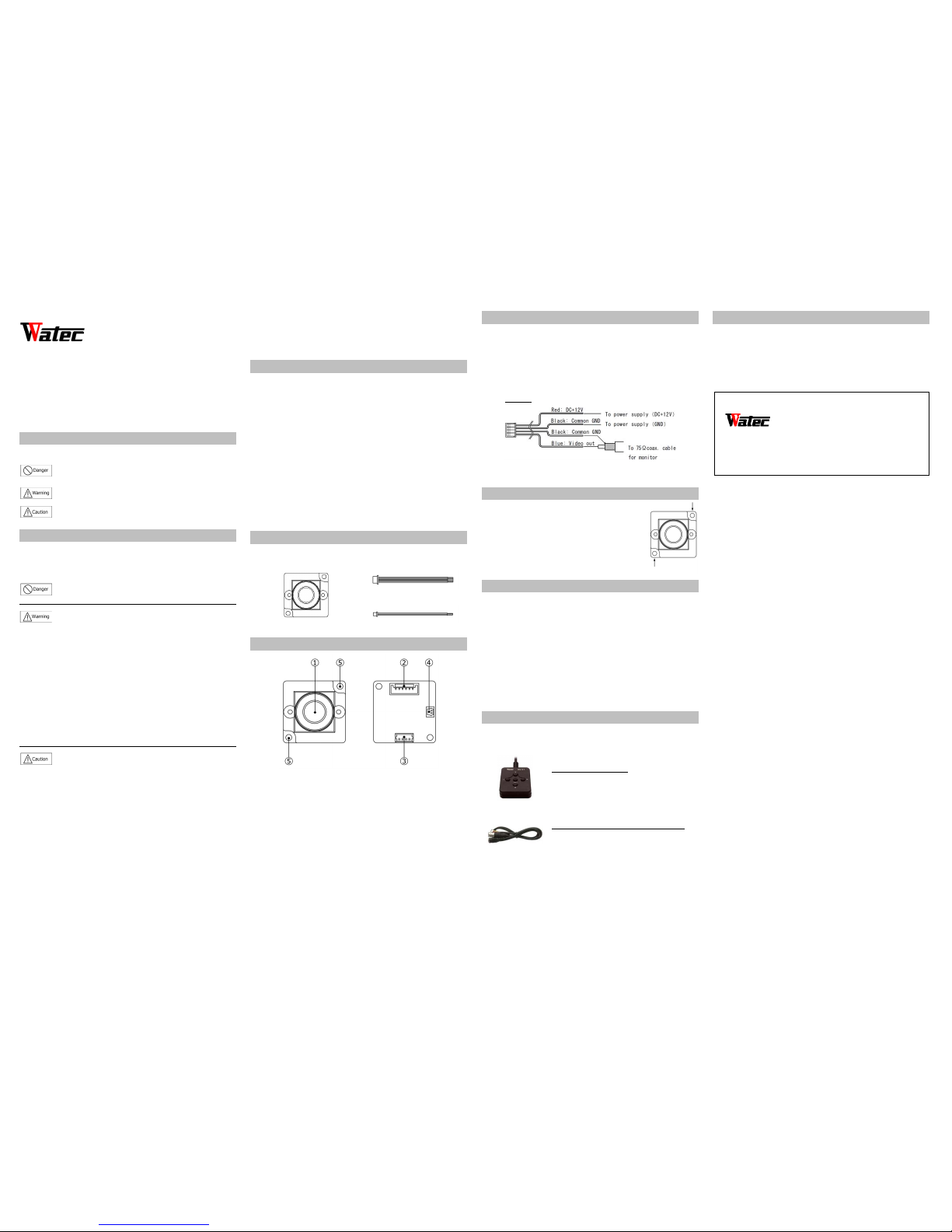
Description of Parts
① LENS FRONT FACE
The light receiving face of the Lens (Dirt, water or oil deposits on the lens
will cause an unclear picture on the monitor. Attach the lens cap to
protect the lens from contamination and damage.)
② OSD (On Scre en Display) CONNECTOR
The terminal designed for connection with remote control for setting the
functions on the screen.
③ POWER IN / VIDEO OUT
The terminal for power input and video signal output. Use the attached
4P cable for this purpose.
④ POWER SUPPLY CONTROL CONNECTOR for LED
The terminal controls power output (3.3V) for LED in PWM method.
Connect the 2p cable for its use. The came ra automatically controls the
brightness of attached LED.
⑤ MOUNTING H OLES
Four φ2.2mm diameter holes in each corner for mounting the camera.
Power Supply and Wiring
Use a stabilized power adaptor designed for DC+5V to 12V, with a current
capacity of more than 250mA
The wiring on the connector must be exact.
Be careful not t o touch the other terminal while wiring. Protect the wiring
portion by using insulation tape after wiring. If the above care and attention
is not adhered to, damage to the WAT-1100MBD and power adaptor may
occur or may cause fire.
4P Cable
Mounting Holes
As shown in the figure on the right, the WAT-1100MBD
provides two mounting holes, one in each corner of the
circuit board. Fix the unit securely using M2 screws.
Once the board is secured proceed with the following
steps below.
Set-up and Operation
1) Refer to the “Power Supply and the wiring” must be exact.
2) Join the video out cable with the video in cable of the monitor or
peripheral equipment.
3) Join the power supply using the correct procedure.
4) Make sure that a picture can be seen on the monitor.
5) To focus, turn the lens clockwise or counterclockwise while observing
the picture on the monitor. Take care when focusing not to scratch or
damage the lens.
Options
To purchase these options, please contact the distributor or dealer from
which you purchased the WAT-1100MBD.
Remote Controller (RC-01)
Remote control for controlling the On Screen
Display menu to change camera settings.
Cable with BNC, socket and connector (CB-01)
The cable with BNC/DC socket.
(Cable Length: 1m)
Contact information
Design and specifications are subject to change without notice.
Watec is not responsible for any inconvenience or the attendant damages
to the video and monitoring recording equipment caused by misuse,
miss-operation or improper wiring of our equipment.
If for any reason the WAT-1100MBD does not work properly, or if you have
any questions regarding installation or operation, please contact the
distributor or dealer from which it was purchased.
Contact information
Watec Co., Ltd.
Add.: 254-2 Nihonkoku, Daihoji, Tsuruoka- Shi,
Yamagata-Ken, 997-0017 Japan
TEL: +81-235-23-4400 FAX: +81-235-23-4409
Email: info-o@watec.co.jp
URL: http://www. watec.co.jp
1693Z00-Y2000002
 Loading...