

Watchman 7820-A, 7825-B, 7830-R, 7835-BR Installation Manual
TM
Models 7820-A, 7825-B, 7830-R & 7835-BR
LED LIGHT BAR INSTALLATION MANUAL
Your purchase of a Wolo warning light is the perfect choice to compliment your vehicle. Wolo’s warning lights are
manufactured with the nest materials. Before being packaged, each light is tested to meet our high standards
and ensure a perfect working light. Our quality workmanship and components are Wolo’s assurance that this
product will provide years of dependable service. If you need help or have any questions using your new Wolo
warning lights, our technicians are available to answer your questions, Monday thru Friday, from 9 AM to 4 PM
EST at 888-550-4676.
Before installation of the light bar is attempted, it is important to read these instructions completely. The lives of
people are dependent on a proper installation of the light bar to the vehicle. The person installing this light bar
must have advanced knowledge of the proper method for mounting and securing the light bar to a vehicle’s roof
or exterior, as well as knowledge of the vehicle’s electrical system. Again, read this manual completely and note
any messages marked “IMPORTANT” or “WARNING’’. A safe installation will prevent serious injury or damage
to the vehicle.
WATCHMAN comes completely wired and does not require any internal wiring by the installer. The power
cable has all the required wires with factory installed terminals and connectors for a successful installation.
Installation of the WATCHMAN Light Bar requires drilling into the vehicle. The installer must carefully inspect
both sides of the selected locations to ensure that there are no components, wires and/or any other vehicle part
that could be damaged by drilling. IMPORTANT: Always de-burr any drilled holes, ensuring that there are no
sharp edges. Install a rubber grommet into all metal holes that the wires are being routed through.
Always refer to the vehicle’s shop manual for deployment location of air bags. Never install the light bar’s switch
control panel, wires and or components in the deployment area of any air bag. Improper installation could reduce
the effectiveness of the vehicle’s air bag system and or project an object that could cause serious personal injury
or death to driver and passenger. The user/installer assumes all responsibility to properly access a safe mounting
location of the light bar’s control panel, to provide ultimate safety to the driver and passengers inside the vehicle.
The vehicle operator and or maintenance department should inspect the light bar frequently to ensure all
brackets are securely attached to the vehicle and that all mounting hardware is free of corrosion.
The light bar’s control panel should be mounted in a location where the switches can be easily reached. Never
attempt to turn light bar on/off when driving under hazardous conditions.
These installation instructions should always be kept and stored in a safe location so that they can be referred
to when information, maintenance or reinstallation is required.
Failure to follow all safety precautions and installation procedures outlined in these instructions could result in
property damage to the vehicle, serious injury or death to you or others.
Fig. 1
MOUNTING LIGHT BAR
1. Position and secure the mounting brackets to the bottom of the light bar using the
hardware pre-installed to the aluminum base plate. Do not fully tightened the nuts
because the brackets need to be positioned in step number 7. See Fig. 1.
2. Place the light bar on the selected location of the vehicle’s roof. A preferred
mounting position on the roof is close to the B-pillar, which is the strongest part
of the roof. IMPORTANT: Make sure the light bar is facing the correct direction.
NOTE: there is a label on the light’s front lens indicating the take down lights.
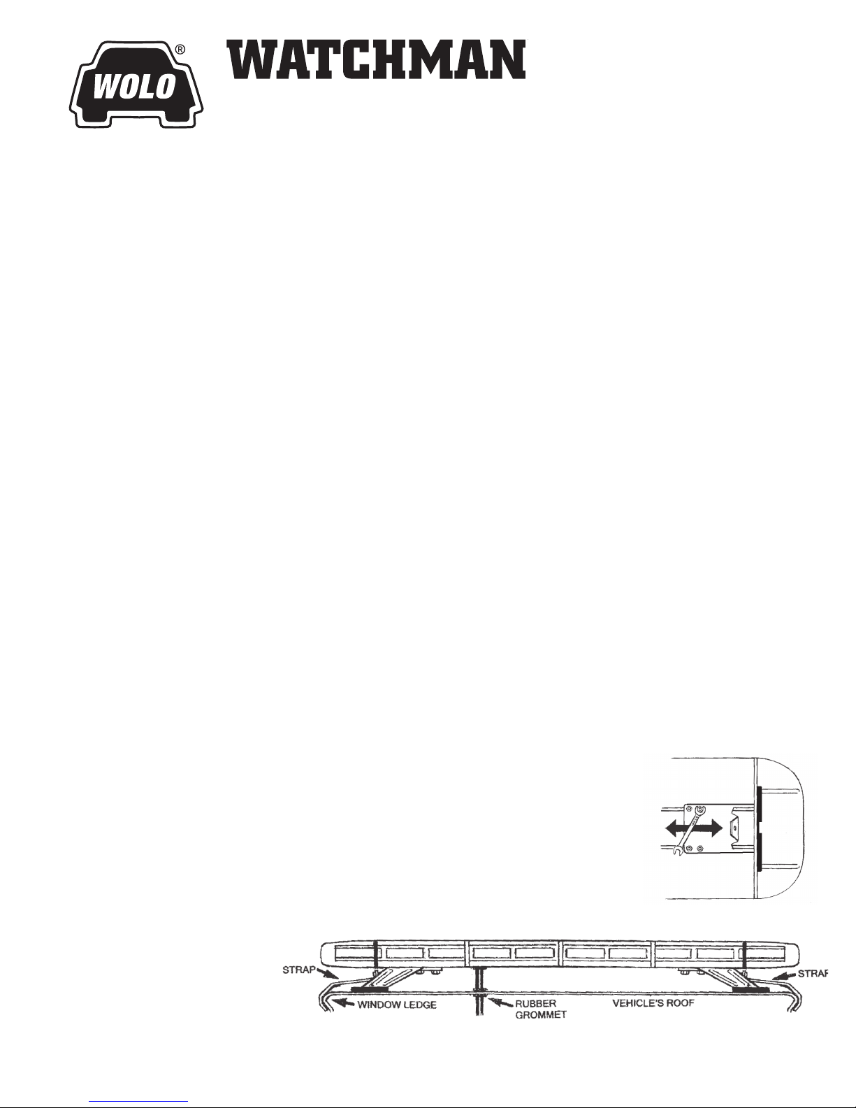
3. Make sure the selected
location of the light bar
will allow the stainlesssteel straps to attach to
the vehicle window ledge
on both the driver’s and
passenger sides. See Fig. 2.
Fig. 2
Front View
WOLO WATCHMAN MODELS - PAGE 1
4. Drill an 11/16“ hole into the roof, which will be the access point to route the cables into the interior of
the vehicle (when at step number 13). Mark the desired hole location; remove the light bar from the roof
and drill the hole. The installer must lower the headliner to carefully inspect selected location to ensure
that there are no components, wires and or any other vehicle part that could be damaged before drilling.
WARNING: The roof has support members that span across from the driver’s and passenger side of the
vehicle. NEVER drill into a support member! It will be necessary to relocate cable’s access hole to not
come into contact with support member.
5. IMPORTANT: Protect the vehicle’s interior headliner from damage that could be caused when drilling the
access hole for the light bar’s power cable. Always allow a minimum distance of 6“ to 8” between the roof
and headliner by lowering the headliner before drilling the access hole.
6. IMPORTANT: Always de-burr the access hole by using a round le to ensure there
Fig. 3
are no sharp edges. NOTE: The light bar’s power cable has a rubber grommet in
place that will be inserted the access hole after the cable is routed into the vehicle
(when at step number 15). See Fig. 3.
7. Position the light bar back onto the roof of the vehicle. There are two adjustable
brackets located on the bottom of the light bar. The installer will need to adjust
RUBBER
GROMMET
the location of the two brackets, each having two- (2) rubber pads, to be close
to the edge of the roof. IMPORTANT: Always make sure that each of the
Fig. 4
protective rubber pads are in full contact with the roof. To adjust each bracket,
loosen the four 5/16” bolts, slide the bracket into position, and tighten the bolts
securely. Repeat the same procedure for the bracket on the other end of the
light bar. See Fig. 4.
8. Open the vehicle’s door and determine the location that the stainless-steel strap
will clamp to the windows ledge. You may need to move the rubber weather-
strip away from the vehicle. Only remove enough weather-strip so that the
area where the stainless-steel strap will be secured to the vehicle is exposed.
Repeat the procedure for other side of vehicle.
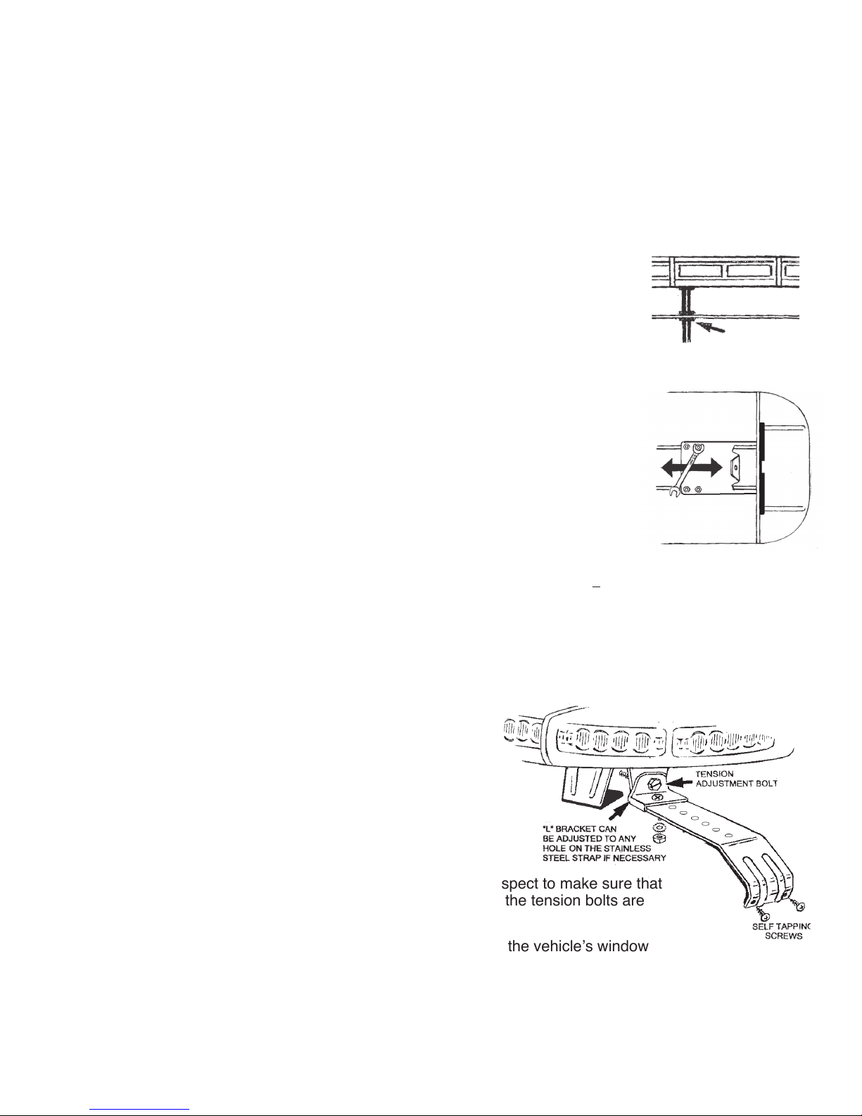
9. Remove the protective lm covering the stainless-steel straps. Place one of the stainless-steel straps
into position on the window ledge so the installer can determine which holes
in the stainless-steel strap
is best positioned to attach the “L” bracket using the bolts, washers and nuts provided. Insert the tension
adjustment bolt through the strap’s “L” bracket and thread bolt into the light bar’s bracket, hand tighten.
IMPORTANT: The “L” bracket can be repositioned for proper installation by simply removing the bolt
securing it to the stainless-steel strap. Reposition and secure the “L” bracket in preferred location using
the bolt, lock washer and nut. Repeat the procedure for other side of vehicle. WARNING: The two- (2)
stainless-steel straps included with the light bar are universal
and should securely install to the window ledge of most
Fig. 5
vehicles. Some vehicles may require a custom designed
strap to properly secure the light bar to the vehicle’s window
ledge. Always make sure that both straps have a full hold on
the vehicles window ledge.
10. Tighten the two- (2) tension adjustment bolts evenly. While
tightening the bolts make sure the light bar remains in the
desired mounting position on the roof. Torque bolts to 1012 ft.-lbs. Failure to properly tighten the tension adjustment
bolts and straps could result in damage to the vehicle and
injury or death to the driver or others. IMPORTANT: Always inspect to make sure that
both straps have a full hold on the vehicles window ledge and the tension bolts are
torqued correctly. See Fig. 5.
11. The hooked end of the stainless-steel strap that is engaged to the vehicle’s window
ledge has two holes, which will secure the bracket to the vehicle with the sheet metal
screws provided. Use each of the holes in the bracket as a template mark and drill the required holes into
the window ledge, drill to size 5/32”. Secure the stainless-steel strap to the window ledge with the sheet
metal screws. IMPORTANT: The installer may have to lower headliner and inspect the selected location
to ensure that there are no components, wires and or any other vehicle part that could be damaged by
drilling. See Fig. 5.
WOLO WATCHMAN MODELS - PAGE 2
 Loading...