

Page 1

Design for Manufacturing and Environment Document
\
Document Number: 480-2521-001
De-manufacturing
EDGE Wireless
Instructions
WatchGuard Technologies. Doc #480-2521-001 Rev. A Page 1 of 8
Authorization and Revision History for this document is available in the WatchGuard ECO system
Page 2
Design for Manufacturing and Environment Document
1.0 Purpose
This instruction defines the de-manufacturing process for the recovery of this product
family as it pertains to recycling of the major product components.
2.0 Scope
This instruction applies to the following product family and family part numbers.
Product Family Name Family part #’s (not necessarily inclusive)
Firebox X Edge Wireless
• Firebox X5W; all revisions
• Firebox X15W; all revisions
• Firebox X50W; all revisions
WatchGuard Technologies. Doc #480-2521-001 Rev. A Page 2 of 8
Authorization and Revision History for this document is available in the WatchGuard ECO system
Page 3
p
3.0 Instruction
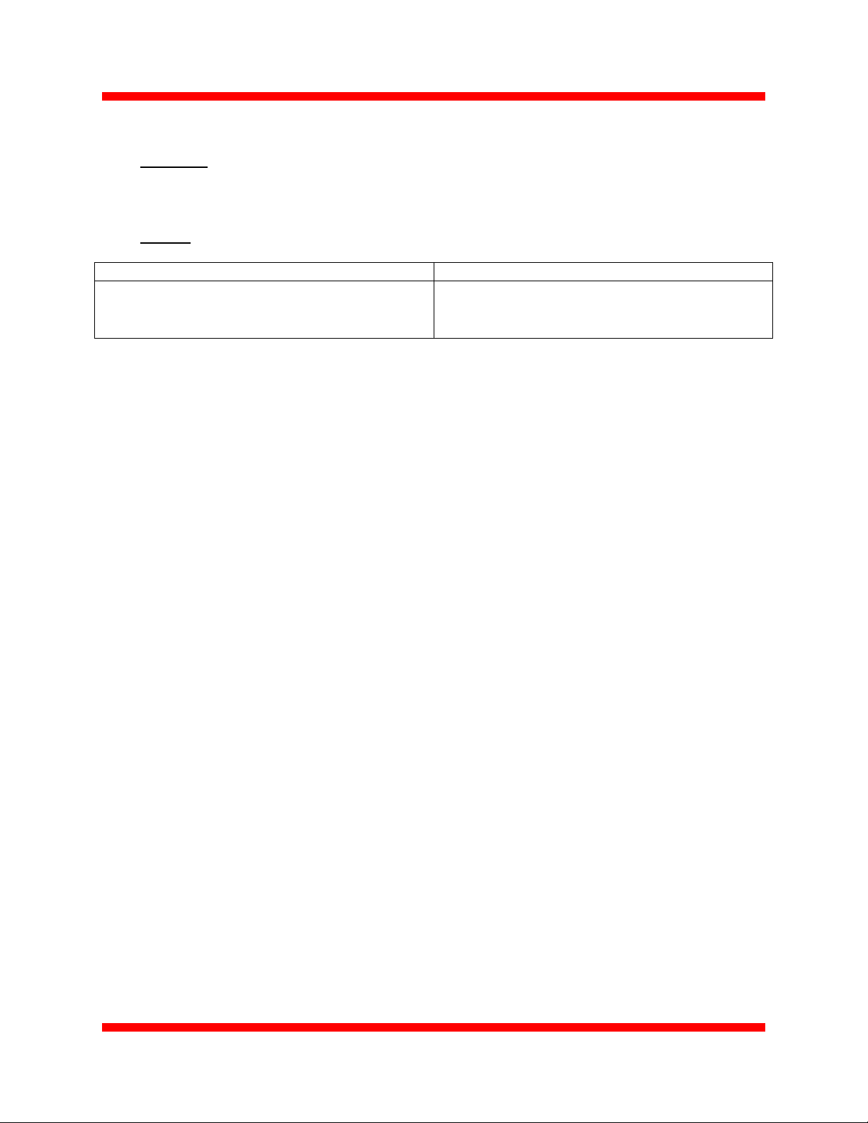
3.1 -Remove wireless antenna and antenna hardware
Material removed (P/N
& material type)
Antenna
1305-002 - TPE, PC,
reverse SMA connector, RG178 coaxial cable; 2.4Ghz; 2
ea.
Design for Manufacturing and Environment Document
Instruction visual
Remove antenna by
unscrewing from chassis
ost, 2 sides
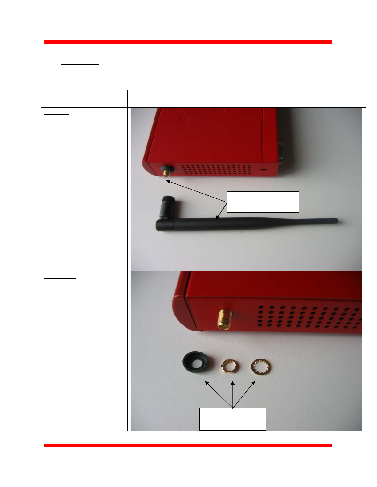
Post cover
1366-001- Rubber Santoprene 10155A
Washer
No p/n - Gold plated brass
Nut
No p/n - Gold plated brass
Remove post cover and
hardware; 2 sides
3.2 -Remove labels, rubber feet and screw, and separate top from bottom
WatchGuard Technologies. Doc #480-2521-001 Rev. A Page 3 of 8
Authorization and Revision History for this document is available in the WatchGuard ECO system
Page 4

Material removed (P/N
& material type)
Labels
Cert. label:
1791-0xx – Metalized
poly-film
Serial number:
1789-00x – Poly-film
Transmit Cert/FCC/CE:
2111-00x – Metalized
Poly-film
Made in Taiwan (if appl):
1794-00x - Metalized
poly-film
CM identifier:
No p/n – Poly-film
Rubber Feet
1422-002 - Polyurethane
Remove screw
2130-002 - Torx pin-head
security screw; stainless
steel
Design for Manufacturing and Environment Document
Instruction visual
Remove rubber feet
Remove labels
Remove screw,
security head
Separate top from bottom
WatchGuard Technologies. Doc #480-2521-001 Rev. A Page 4 of 8
Authorization and Revision History for this document is available in the WatchGuard ECO system
Page 5

3.3 – Remove serial connector standoffs
Material removed (P/N
& material type)
Stand-offs
No p/n – Hex-head;
stainless steel
Design for Manufacturing and Environment Document
Instruction visual
Remove stand-offs
3.4 – Remove bezel from unit top - depress tabs to disengage; remove light pipe
from bezel
Material removed (P/N
& material type)
Painted metal enclosure
1768-001 - 22Ga. EG
w/powder coat (Interpon 700
-epoxy/polyester)
Light-pipe
1587-001 - PC
Bezel
1590-001 - PC/ABS
Instruction visual
Depress tabs to
disengage
Remove light pipe; clear PC
WatchGuard Technologies. Doc #480-2521-001 Rev. A Page 5 of 8
Authorization and Revision History for this document is available in the WatchGuard ECO system
Page 6

3.5 –Remove battery; remove screws and separate main PCBA from chassis
bottom
Material removed (P/N
& material type)
Battery –coin cell
0301-001– Manganese
oxide / Lithium CR2032
Remove screws
0863-002 - Phillips head,
stainless steel, 4 ea.
Design for Manufacturing and Environment Document
Instruction visual
Remove battery from clip
Remove PCBA screws -4 ea.
Separate PCBA from
chassis bottom
3.6 –Remove insulator shields from bottom chassis
WatchGuard Technologies. Doc #480-2521-001 Rev. A Page 6 of 8
Authorization and Revision History for this document is available in the WatchGuard ECO system
Page 7

Material removed (P/N
& material type)
Painted metal enclosure;
chassis bottom
1769-001 - 22Ga. EG
w/powder coat (Interpon 700
-epoxy/polyester)
Insulator shields
1780-001 - Insulator,
31.3mm round, Mylar, 2 ea.
1767-001 - Insulator,
42x221mm, Mylar, 1 ea.
Design for Manufacturing and Environment Document
Instruction visual
Remove EMI shields
3.7 –Bend RF PCBA clip (up) and remove RF PCBA from main PCBA
Material removed (P/N
& material type)
Main PCBA
1724-001 - Printed circuit
assembly
Instruction visual
Remove RF PCBA
by pulling out
Release connector, 2 sides
Bend clip up
3.8 –Disconnect RF cables from RF PCBA
WatchGuard Technologies. Doc #480-2521-001 Rev. A Page 7 of 8
Authorization and Revision History for this document is available in the WatchGuard ECO system
Page 8

Material removed (P/N
& material type)
RF PCBA
1771-001 - RF PCBA
RF Cable
1772-001 - Coaxial cable
assembly. 6cm
RF Cable
1772-002 - Coaxial cable
assembly. 19.5cm
Design for Manufacturing and Environment Document
Instruction visual
Remove RF Cables from
RF PCBA
4.0 Applicable Documents
5.0 Revision History
REV.
NO.
A 10/10/2005 n/a Initial Release 0712
REV. DATE
REVISED SECTION REASON ECO#
WatchGuard Technologies. Doc #480-2521-001 Rev. A Page 8 of 8
Authorization and Revision History for this document is available in the WatchGuard ECO system
 Loading...