

Watchguard XTM 515, XTM 525, XTM 545, XTM 535 Hardware Manual

WatchGuard
XTM 5 Series
Hardware Guide
XTM 515, 525, 535, 545
NC2AE8

Copyright and Patent Information
Copyright© 1998–2012 WatchGuard Technologies, Inc. All rights reserved.
WatchGuard, the WatchGuard logo, LiveSecurity, and any other mark listed as a trademark in the “Terms of Use” portion of
the WatchGuard Web site that is used herein are either registered trademarks or trademarks of WatchGuard Technologies,
Inc. and/or its subsidiaries in the United States and/or other countries. All other trademarks are the property of their
respective owners.
Printed in the United States of America.
Part Number: 275-4210-001 Rev A
Revised: June 15, 2012
U.S. Patent Nos. 6,493,752; 6,597,661; D473,879. Other Patents Pending.
Complete copyright, trademark, patent, and licensing information
can be found in the WatchGuard product documentation. You can
find this document online at:
http://www.watchguard.com/help/documentation/
Notice to Users
Information in this guide is subject to change without notice. Updates to this guide are posted at:
http://www.watchguard.com/help/documentation/hardware.asp
Companies, names, and data used in examples herein are fictitious unless otherwise noted. No part of this guide may be
reproduced or transmitted in any form or by any means, electronic or mechanical, for any purpose, without the express
written permission of WatchGuard Technologies, Inc.
ABOUT WATCHGUARD
WatchGuard offers affordable, all-in-one network and content security solutions that
provide defense-in-depth and help meet regulatory compliance requirements. The
WatchGuard XTM line combines firewall, VPN, GAV, IPS, spam blocking and URL
filtering to protect your network from spam, viruses, malware, and intrusions. The new
XCS line offers email and web content security combined with data loss prevention.
WatchGuard extensible solutions scale to offer right-sized security ranging from small
businesses to enterprises with 10,000+ employees. WatchGuard builds simple, reliable,
and robust security appliances featuring fast implementation and comprehensive
management and reporting tools. Enterprises throughout the world rely on our
signature red boxes to maximize security without sacrificing efficiency and
productivity.
For more information, please call 206.613.6600 or visit www.watchguard.com
ii WatchGuard XTM 5 Series
ADDRESS
505 Fifth Avenue South
Suite 500
Seattle, WA 98104
SUPPORT
www.watchguard.com/support
U.S. and Canada +877.232.3531
All Other Countries +1.206.521.3575
SALES
U.S. and Canada +1.800.734.9905
.
All Other Countries +1.206.613.0895

Hardware Specifications
Note
WatchGuard® XTM security appliances deliver unparalleled unified threat management, superior
performance, ease of use, and value for your growing network. Our security subscriptions give you fully
integrated protection from spyware, spam, viruses, worms, trojans, web-based exploits, and blended threats.
From firewall and VPN protection to secure remote access, WatchGuard devices support a broad range of
network environments.
This guide introduces the XTM 5 Series, a series of RoHS-compliant (lead-free) hardware products offered by
WatchGuard.
WatchGuard’s XTM 5 Series devices use dynamic, multi-layered security to proactively protect your network.
The XTM 5 Series has the reliability, redundancy, traffic management, and port density that demanding, highspeed networks require.
You can upgrade some XTM 5 Series devices to a higher model in the XTM 5 Series line for more capacity and
performance with a software license key.
This Hardware Guide applies to XTM 5 Series devices with model numbers XTM 515, 525, 535,
and 545. If your 5 Series device has a different model number, your hardware is described in the
XTM 5 Series Hardware Guide that applies to that model.
Fireware XTM OS
The XTM 5 Series devices support WatchGuard’s next generation UTM OS—Fireware® XTM. Each XTM 5 Series
device includes Fireware XTM and delivers exceptional protection against today's sophisticated threats to
make sure that your business stays connected. As an option, you can purchase a Pro upgrade to Fireware XTM
to enable additional advanced networking capabilities. For more information on the features of Fireware XTM
OS, see the current Fireware XTM WatchGuard System Manager Help or Fireware XTM Web UI Help.
Hardware Guide 1

Hardware Specifications
Package Contents
CD-ROM with this Hardware Guide
XTM 5 Series appliance
Quick Start Guide
Hardware warranty card
LiveSecurity® Service activation card
Safety Notices
Declaration of Conformity
1 straight-through Ethernet cable (green)
1 cross-over Ethernet cable (red)
1 serial cable with an RJ45 connector
1 power cord
4 rubber pads for the bottom of the device
1 rack-mounting kit
About Your Hardware
Hardware Specifications
XTM 5 Series
Processor Intel Dual Core
Memory: Flash 1 GB
Memory: RAM 2 GB
Power supply 100-240 VAC
Autosensing
Dimensions D= 11.25” (28.6 cm)
W= 17” (43.18 cm)
H= 1.75” (4.45cm)
Weight 10.15 lbs
Interface Specifications
Network interfaces
• 6x 1000Base-T (10/100/1000 Mbps), RJ45 connector
• 1x 100Base-TX (10/100 Mbps), RJ45 connector
I/O interfaces
2 WatchGuard XTM 5 Series
•2 USB
• 1 RJ45 serial

Environmental Requirements
To safely install your XTM 5 Series device, we recommend that you:
Install it in a network rack
Put it in a secure area, such as a locked room, to block the device from people who do not have
permission to use it
Connect it to a conditioned power supply to prevent damage from sudden power changes
Other environmental requirements:
Operating temperature 0 – 40°C
(32 – 104°F)
Hardware Specifications
Operating relative humidity
Non-operating temperature –40 – 70°C
Non-operating relative humidity 10% – 90%
10% - 85% non-condensing
(–40 – 158°F)
Hardware Guide 3
Hardware Specifications
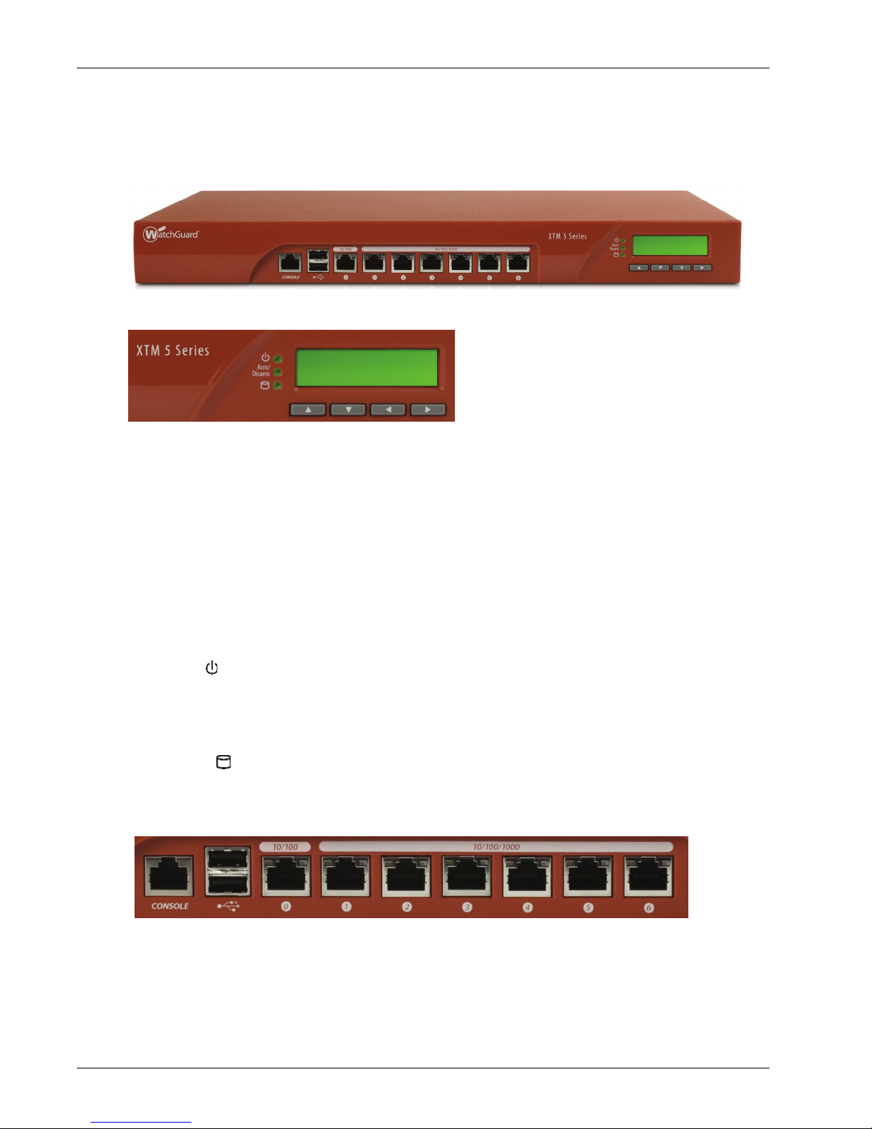
Front View
The front of the device.
This is a close-up of the right side of the front of the device.
LCD indicator panel
Device status information appears on the LCD screen. Press the buttons below the screen to change
the information that appears on the screen.
For more information, see “Use the LCD Interface” on page 8.
LCD console buttons
Press the LCD console buttons to see status information and start recovery procedures.
To boot the device in safe mode, press and hold the down arrow button when you power on the
device.
For detailed information about the LCD indicator panel and the LCD console buttons, see “Use the
LCD Interface” on page 8.
Power ( )
When the device is powered on, the power indicator is green.
Arm/Disarm
When the device is armed, this indicator is green. When the device is disarmed, this indicator is red.
Storage ( )
When there is activity on the compact flash, this indicator is yellow.
All interfaces are on the front of the device.
Serial port (Console)
An RJ45 connector for the serial interface.
4 WatchGuard XTM 5 Series

Hardware Specifications
Note
Dual USB interface
Connect a USB storage device to use for USB backup and restore, or to store a support snapshot.
For more information about USB functions, see the Fireware XTM WatchGuard System Manager Help
or Fireware XTM Web UI Help.
Network Interfaces
The interfaces have standard RJ45 connectors and are labeled 0,1,2,3,4,5,6.
Interface 0 — supports link speeds of 10 or 100 Mbps.
Interfaces 1 - 6 — support link speeds of 10, 100, or 1000 Mbps.
Interface 0 does not support Auto-MDIX, which automatically senses the cable polarity. Use these
guidelines to decide which type of Ethernet cable to use with Interface 0.
To connect Interface 0 to an interface on a switch or router that supports Auto-MDIX, you can
use either Ethernet cable.
To connect Interface 0 to an interface on an older switch or router that does not support Auto-
MDIX, use the green Ethernet cable. Your switch or router could be set to a different polarity. If
the green Ethernet cable does not work, try the red cross-over Ethernet cable.
To connect Interface 0 to a PC, use the red cross-over Ethernet cable.
Indicators for network interfaces
At the top of each labeled network interface, there is a pair of indicators. The indicator at the left of
the interface is the activity indicator for that interface. The indicator at the right shows the connection
speed for that interface.
Indicator Indicator color Interface Status
Activity (upper left) Yellow Power on, connection established
Not lit Power off, no connections
Blinks
Data sent and received
(speed of blink increases as the
data flow increases)
Connection Speed
Not lit Link speed: 10 Mbps
(upper right)
Green Link speed: 100 Mbps
Yellow Link speed: 1000 Mbps
When the device is powered off, but the AC power is plugged in, the Link and Activity indicators for
interface 0 continue to operate, but the interface does not pass traffic. All other network interface
indicators are inactive.
Hardware Guide 5
Hardware Specifications
Caution
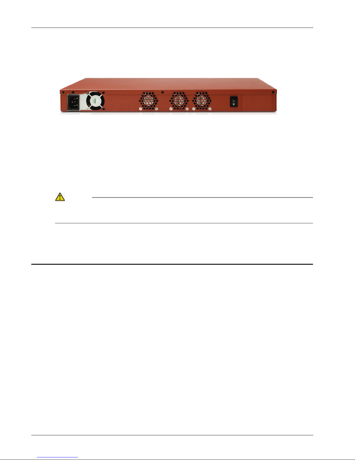
Rear View
The AC receptacle, fans, and power switch are on the rear of the device.
AC receptacle
Accepts a detachable AC power cord supplied with the device. The power supply for the device is a
WatchGuard standard auto-sensing AC power supply.
Fans
The fans decrease the internal temperature of the device.
Power switch
Controls the power supplied to the device. To power on the device, press the switch. To power off the
device, press and hold the switch for at least 5 seconds.
You must disconnect the power supply before you remove the cover of the XTM 5 Series
device. If you open the cover without prior authorization from WatchGuard, this voids the
Hardware Warranty.
Rack Mount Instructions
Each WatchGuard XTM 5 Series device ships with a rack mount kit. When you install the XTM 5 Series device
in a rack, make sure you consider:
Elevated Operating Ambient Temperature
If you install the XTM 5 Series device in a closed or multi-unit rack assembly, the operating ambient
temperature of the rack environment could be greater than the ambient temperature of the room.
The XTM 5 Series device is certified to operate correctly between 0 – 40°C (32 – 104°F).
Reduced Air Flow
When you install the XTM 5 Series device in a rack, make sure that the amount of air flow required for
safe operation of the equipment is not compromised.
Mechanical Loading
When you mount the XTM 5 Series device in the rack, avoid hazardous conditions caused by uneven
mechanical loading.
Circuit Overloading
Make sure you connect the XTM 5 Series device to the power supply circuit to make sure there is no
overloading of the circuits, and no impact on overcurrent protection and supply wiring.
Reliable Grounding
Make sure all rack-mounted equipment is correctly grounded. For example, use power strips instead
of direct connections to the branch circuit.
6 WatchGuard XTM 5 Series
 Loading...