

Page 1
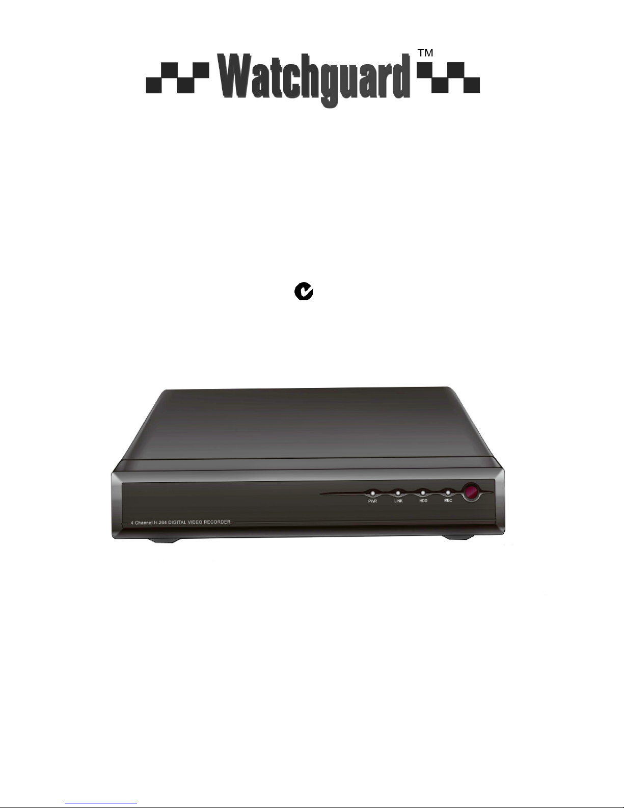
FOR MODELS: DVR4EONPACK & DVR8EONPACK
Professional Surveillance Pack
Digital Video Recorder with Security Camera s
‘QUICK INSTALLATION GUIDE’
DVR 15m IR Day/Night Cameras
- H.264 Video Compression Technology - High Quality Image sensor
- Multiplex Operation - 26 x IR LEDs
- Long Recording Duration - 420 TVL Resolution
- Intelligent Video Motion Detection Recording
- Remote Network Surveillance & Backup Functions
- Easy to operate with remote or USB mouse
- System Auto recovery after power loss (blackout)
N517
www.watchguardalarms.com.au
Page 2
1
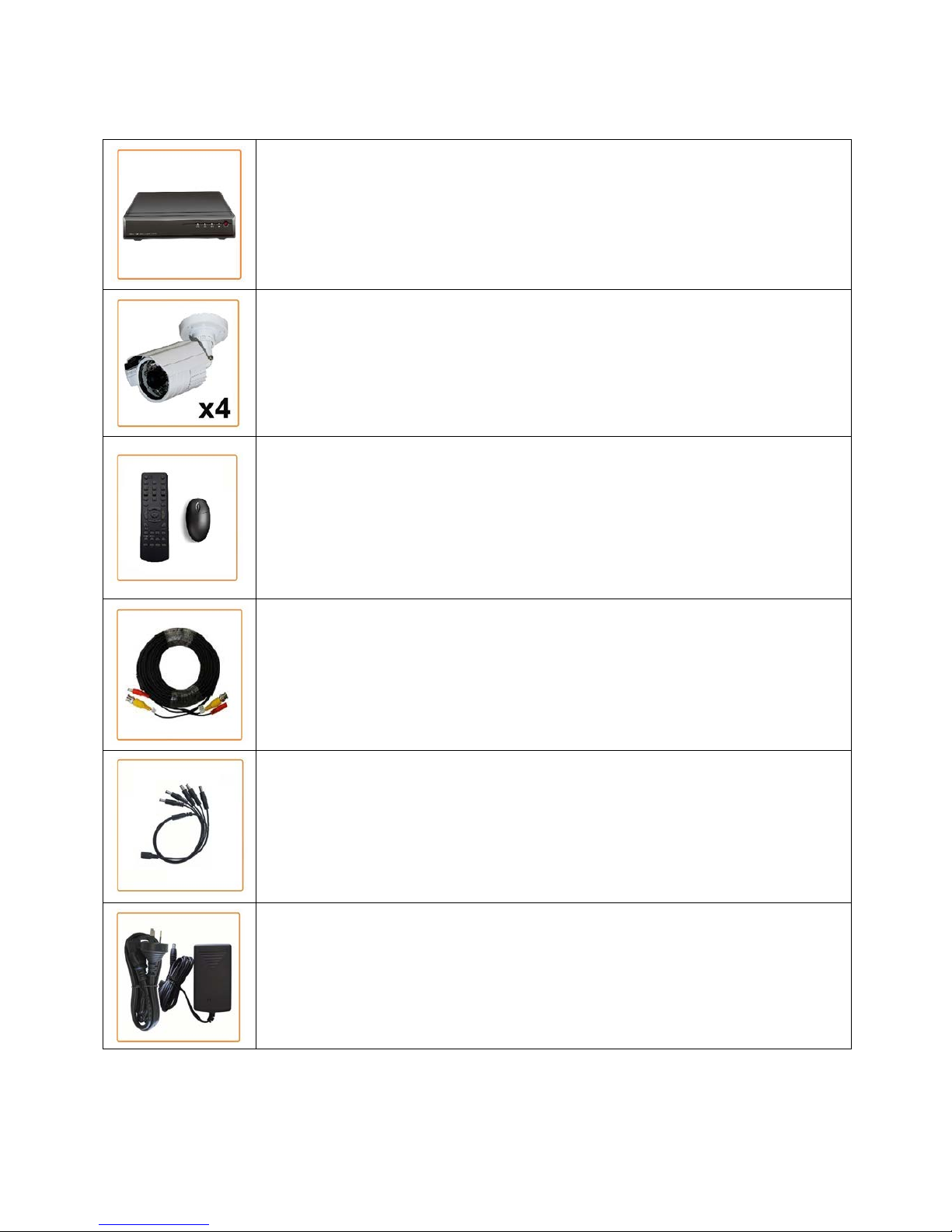
DVR4EONPACK Package Contents
(Before commencing installation, please ensure you have all the parts listed below.)
1 x 4ch Digital Video Recorder with 1TB Hard Disk Drive
● Advanced H.264 Video Compression Technology for High Quality Images and Small
File Sizes
● Easy to Operate - Just Like a VCR
● Can be Connected to a PC Network for Remote Viewing & Backup (Software on CD)
● For More Details, Please See Bottom of this Box
4 x Day/Night Weatherproof Colour Cameras with Infrared LEDs - 15m Range
● High Quality Image Sensor
● IR LEDs for Viewing in Total Darkness up to 15m (B/W Mode)
● 420 TVL Resolution
● Compact Size Ideal for Use Indoors or Out
1 x IR Remote Control
● Allows You to control the DVR like a Television.
1 x USB Mouse
● Allows You to control the DVR like a PC.
4 x Camera Connection Cables
● Combined DC Power and Video Leads
● Pre-terminated - Allowing Simple Plug-in Connection – No T ools Required
● 4 x 18m Leads Supplied
1 x Power Split Cable
● Allows You to Connect All 4 Cameras and the DVR to 1 Power Suppl y
1 x Switch Mode Low Voltage Power Supplies
● 1 x 12VDC Supply for Use with the Power Split Cable to Power All Cameras
* Note: If you wish to connect directly from the DVR to a PC you require a crossover cable (Not Included)
Page 3
2
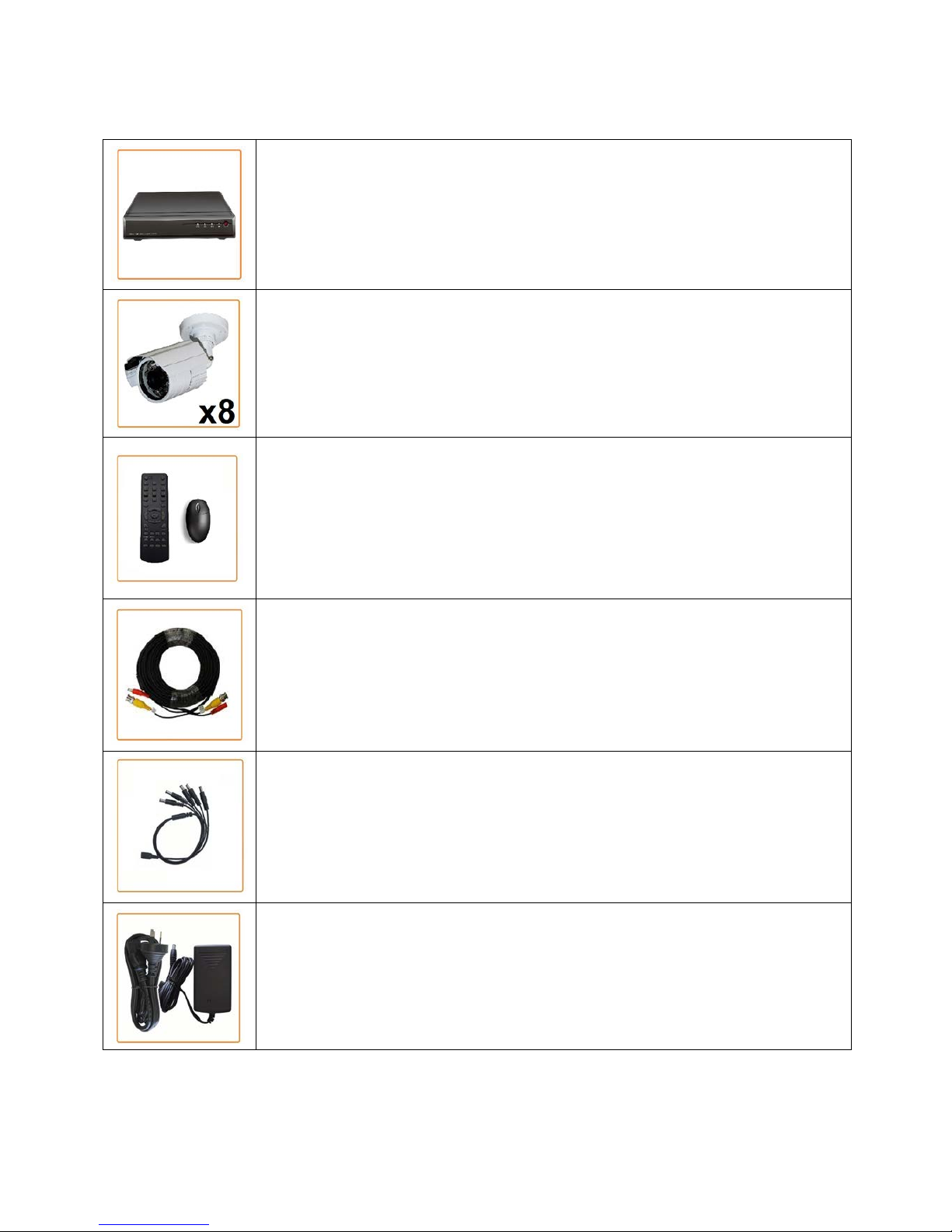
DVR8EONPACK Package Contents
(Before commencing installation, please ensure you have all the parts listed below.)
1 x 8ch Digital Video Recorder with 1TB Hard Disk Drive
● Advanced H.264 Video Compression Technology for High Quality Images and Small
File Sizes
● Easy to Operate - Just Like a VCR
● Can be Connected to a PC Network for Remote Viewing & Backup (Software on CD)
● For More Details, Please See Bottom of this Box
8 x Day/Night Weatherproof Colour Cameras with Infrared LEDs - 15m Range
● High Quality Image Sensor
● IR LEDs for Viewing in Total Darkness up to 15m (B/W Mode)
● 420 TVL Resolution
● Compact Size Ideal for Use Indoors or Out
1 x IR Remote Control
● Allows You to control the DVR like a Television.
1 x USB Mouse
● Allows You to control the DVR like a PC.
8 x Camera Connection Cables
● Combined DC Power and Video Leads
● Pre-terminated - Allowing Simple Plug-in Connection – No T ools Required
● 4 x 18m Leads Supplied
1 x Power Split Cable
● Allows You to Connect All 8 Cameras to a Power Supply
2 x Switch Mode Low Voltage Power Supplies
● 2 x 12VDC Supply for Use with the Power Split Cable to Power All Cameras
* Note: If you wish to connect directly from the DVR to a PC you require a crossover cable (Not Included)
Page 4
3
DVR4EONPACK Installation
Before installing this unit, please read through the following points:
• Do not place cords from the AC adapter where they can be pinched or stepped on.
• Do not place heavy objects on cords, or cover cords with rugs or carpet.
• Never immerse any component in water, and do not spray cleaners of solvents on the unit. Unplug
units before cleaning. When cleaning, use a damp, lint-free cloth only.
• Do not expose the DVR or Cameras to excessive heat, cold, or moisture
• Leave at least a 50mm between the DVR and other objects for air circulation around the unit.
• Service should be handled by qualified technicians.
Connection Guide
1. Locate the 4 Cameras as required and connect the supplied combination DC Power and Video
leads.
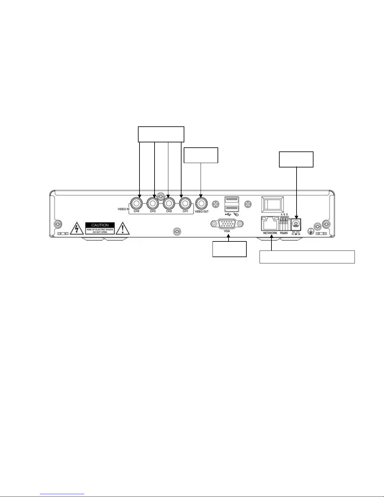
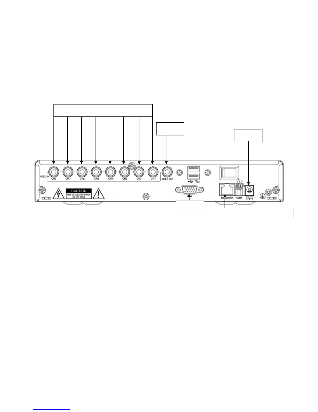
2. Connect the 4 x corresponding camera Video leads into the camera inputs at the rear of the DVR
(Figure A). Be sure to take note of the Camera input 1 – 4, as this will determine the camera
channels.
3. Connect the 4 x camera Power leads into the Power Splitter Cable
4. Connect the other Power Supply Cable to the DVR (Figure D).
5. If you are using a TV/Monitor with Composite Video Input, follow Step 6.
If you are using a TV/Monitor with VGA input, follow Step 7.
6. Connect the Monitor Connection Cable into the Composite Monitor output on the rear of the DVR
(Figure B). Connect the Monitor Connection Cable into the RCA Video input on your TV/Monitor
(TV/Monitor Not Supplied).
7. Connect the VGA cable to the VGA output on the rear of the DVR (Figure C). Connect the other end
of the VGA cable into the TV/Monitor VGA input.
8. Connect the 12VDC Power adaptor to the Power Split Cable.
9. Plug the Power adaptor into a Power-Point and switch the power-point ON
10. Th e Power LED on the front of the DVR should now be illuminated and the unit will make a loud
beep sound to show that it is ready.
Figure B
Figure C
Network cable connection (Optional Use)
Figure A
Figure D
Page 5
4
DVR8EONPACK Installation
Before installing this unit, please read through the following points:
• Do not place cords from the AC adapter where they can be pinched or stepped on.
• Do not place heavy objects on cords, or cover cords with rugs or carpet.
• Never immerse any component in water, and do not spray cleaners of solvents on the unit. Unplug
units before cleaning. When cleaning, use a damp, lint-free cloth only.
• Do not expose the DVR or Cameras to excessive heat, cold, or moisture
• Leave at least a 50mm between the DVR and other objects for air circulation around the unit.
• Service should be handled only by qualified technicians.
Connection Guide
11. Locate the 8 Cameras as required and connect the supplied combination DC Power and Video
leads.
12. Connect the 8 x corresponding camera Video leads into the camera inputs at the rear of the DVR
(Figure A). Be sure to take note of the Camera input 1 – 8, as this will determine the camera
channels.
13. Connect the 8 x camera Power leads into the Power Splitter Cable
14. Connect the other Power Supply Cable to the DVR (Figure D).
15. If you are using a TV/Monitor with Composite Video Input, follow Step 6.
If you are using a TV/Monitor with VGA input, follow Step 7.
16. Connect the Monitor Connection Cable into the Composite Monitor output on the rear of the DVR
(Figure B). Connect the Monitor Connection Cable into the RCA Video input on your TV/Monitor
(TV/Monitor Not Supplied).
17. Connect the VGA cable to the VGA output on the rear of the DVR (Figure C). Connect the other end
of the VGA cable into the TV/Monitor VGA input.
18. Connect the 12VDC Power adaptor to the Power Split Cable.
19. Plug the Power adaptor into a Power-Point and switch the power-point ON
20. The Power LED on the front of the DVR should now be illuminated and the unit will make a loud
beep sound to show that it is ready.
Figure B
Figure C
Network cable connection (Optional Use)
Figure D
Figure A
Page 6
5
Quick Start up Guide
• Make sure your TV/Monitor is ON and set to the appropriate AV channel if required
• The Power LED will illuminate Green. It takes approximately 10 to 15 seconds to boot the
system.
• T he images from all cameras should now be displayed on your TV/Monitor
• BEFO RE BEGINNING TO RECORD YOU MUST SET the DATE and TIME on your DVR.
Setting the Date and Time
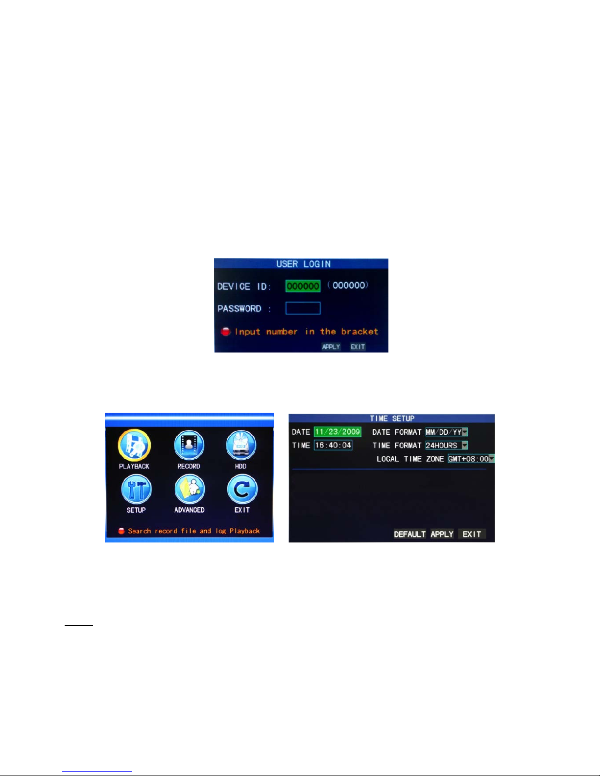
• Press “MENU” on the DVR front panel to bring up the dialogue box. Use the mouse or remote to
enter the DVR login, with the on-screen keypad.
The default Device ID is 000000, the default password is to be left blank.
(Users can alter the password later. Please refer to the Advanced set up guide CD)
• Press “MENU” on the DVR front panel to bring up the main menu. Select “SETUP” “TIME
SETUP” to set the date and time
IMPORTANT NOTE
: Please DO NOT change the date or time on your DVR after the recording function is
activated. The recorded data will be disordered and you will not be able to find the recorded file to backup by time
search.
NOTE: If users change the date or time accidentally when the recording function is activated, it’s recommended to
clear all HDD data, and start recording again.
Page 7

6
Menu Display and Operation with USB Mouse
The system supports operation via USB mouse. See below for an explanation of how to operate your
DVR using the mouse input.
Connect USB Mouse
- Connect your USB mouse to one of the USB ports on the DVR front panel
- Use the mouse to enter the DVR password with the password keypad.
- Default Device is 000000, the default password is to be left blank.
Mouse action Function
Right button Enter system main menu: real-time screen preview, single mouse left click
Double mouse
left click
Single left click the functional menu icon, and enter menu setting page
The image in a channel can be enlarged by double click real-time monitoring and playbac k screen, it
can be recovered into monitoring and multi-split image af ter doub le cli ck again
Click the left
mouse button
Access to volume adjustment, color adjustment and PTZ control menu. The volume adjustment, color
adjustment and PTZ control can set only one channel, please select corresponding screen if
multi-screen mode is on prior to setting.
If you single click mouse button in volume adjustment and PTZ control:
PTZ control is available if clicking direction or "+ and -" icon;
There is a volume bar in volume control interface. Move mouse to a position and click right button, the
corresponding volume will be shown in the right side of the volume bar, click "X" to exit;
The operations like color adjustment can be referred to above volume adjustment.
If there are many options in the option box, click the left button and drop-down menu will be shown.
Fast forward and fast backward function can be realized by left clicking in video playback interface.
Click the left button or right button can activate the soft keyboard in input box, clicking right button can
switch English and Chinese input state; the number, symbol and English word capitalization can be
realized only by clicking.
The Chinese spell is also available via the soft keyboard input when Chinese input, its input method is
as same as remote control; left button can be used for turning page.
Mouse
movement
Click left button and move can adjust the parameters in volume adjustment and color adjustment
interface, there is corresponding parameter display in right side when movement.
Click left button and move the motion box can set the dynamic detection zone in motion detection
zone.
Page 8
7
Recording mode
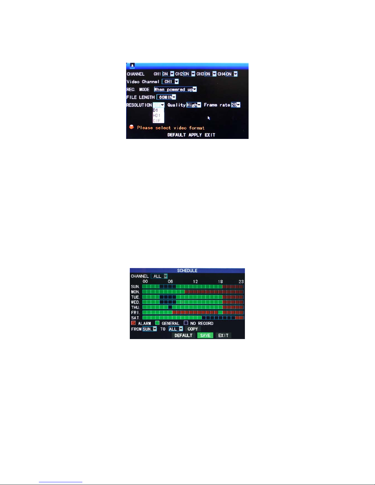
Enter the Recording Mode screen from “Main Menu”>“Record”, as shown below:
CHANNEL: used to select if the video recording function is enabled for the corresponding recording
channel.
RESOLUTION: available in the 3 levels of D1(704*576), HD1(704*288)and CIF(352*288)(Note: This
option is available for 4-channel DVR only, and the resolution of 8-channel DVR is CIF by default.)
QUALITY: 3 levels available are high, normal and low, which correspond to the 3 data stream standards
of high, normal and low bit rates.
REC.MODE: there are two available modes recording. These are “When powered up” and “By Time”.
When powered up: The DVR will record when powered on.
By Ti m e : The DVR will record as per its schedule. When “timing recording” is selected, the “Record
Time Configuration” button will appear on the right. Move the cursor here and press “Enter” to enter
the Record Time Configuration screen, as shown below:
Channel: You may choose either “All” or a single channel.
Time configuration: First select from the 3 modes of alarm recording, general recording and no
recording for your desired recording mode for a certain lattice, and configure specific recording time
lattices (each lattice represents 1hr). Each lattice can be configured into different recording modes
by marking them into different colors, such as red, green and background color, which represent
alarm recording, general recording or no recording within each hour respectively.
FILE LENGTH: Left-click or press “Enter” to select the File length, with the 4 options of 15min, 30min,
45min and 60min.
Page 9
8
Video search
Press “MENU” on the DVR front panel to bring up the main menu. Select “PLAYBACK” to as shown
below.
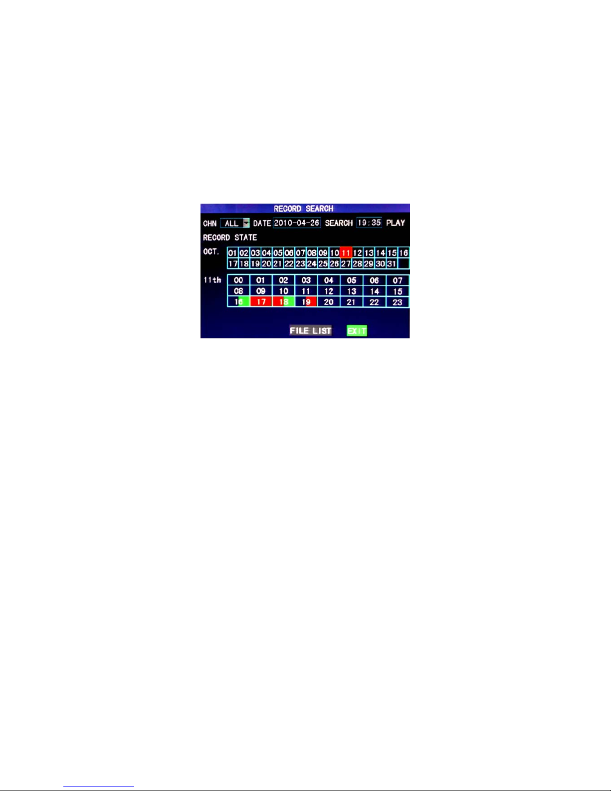
To playback, first select the corresponding camera channel then choose the DATE and click “SEARCH”.
Next select the TIME and press “PLAY”. This will begin playing the selected time.
Alternatively you can select the corresponding camera channel then choose the DATE and click
“SEARCH” to view the record state of this date, as shown below:
Month: displaying the record information of every day in the current month. A green block indicates
normal recording, a red block indicates alarm recording, and the background color indicates no
recording. Click a date on this bar to search the record information of every hour of that day. The
search results will be visualized in the “Day” bar below.
Date: displaying the recording hours of the current day. Each lattice represents 1hr, and one recording
segment is 0.5hr. The presentation of the record state is the same as above. Click a 0.5hr segment of a
day directly to enter the record playback of this segment.
Page 10
9
Backup
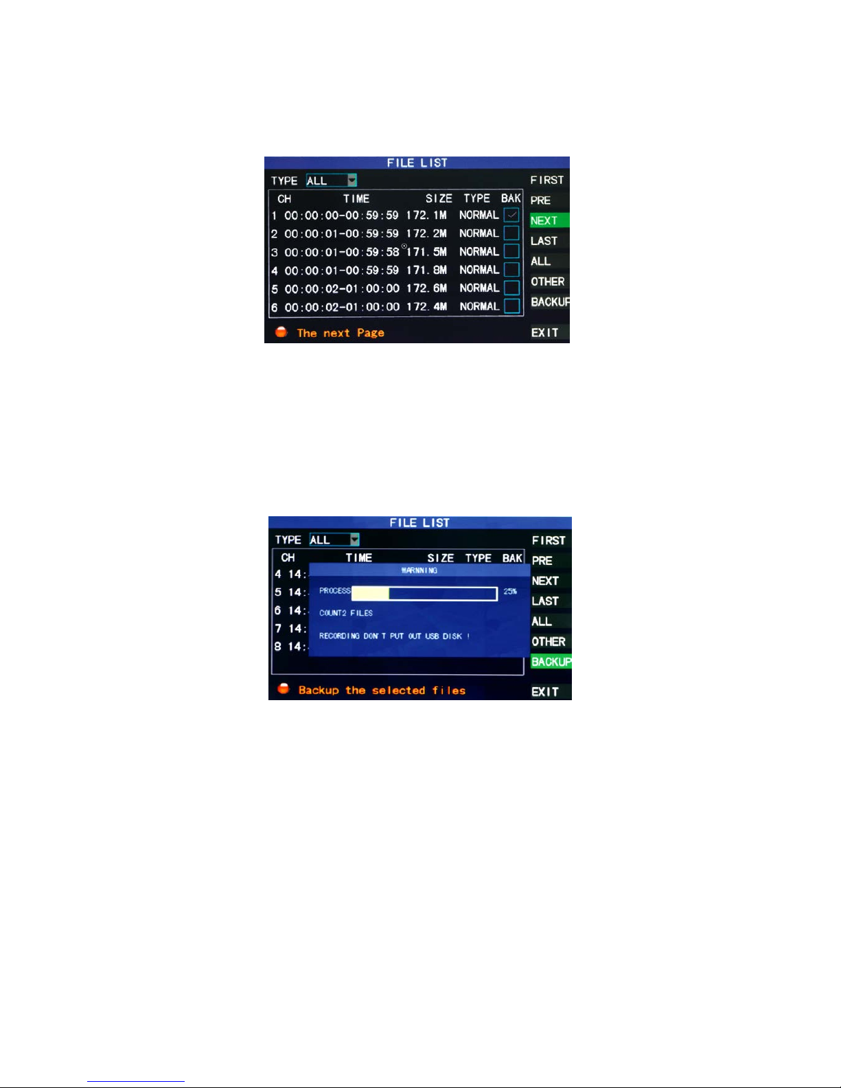
While in the “PLAYBACK” menu, select the corresponding camera channel then choose the DATE and
click SEARCH. Next select the TIME and then select “File List” for the backup operation.
The record file may be backed up by a USB storage device. Before the record file is backed up, the user
must insert the storage device into the USB slot of this unit. This product supports the plug-and-play
operation of USB devices.
Move the cursor up and down in the Detailed File List screen to select a certain record file. After “Enter”
is pressed in the “Backup” check box, a “√” will appear in this box, indicating that this record file has
been selected. The move the cursor to the option box on the right and click “Backup”, when the screen
will display the backup progress message of the file, as shown below:
Note:
When the available space of the backup device is less than the capacity of the recorded file, the
system will prompt the user with “Not Enough Space”
After the recorded files have been backed up, you can unplug the USB device.
Page 11
10
Networking
Important: Before setting up remote access for your DVR, you will need to have a good understanding of
computer networking. Otherwise please seek the assistance of a qualified I.T. person.
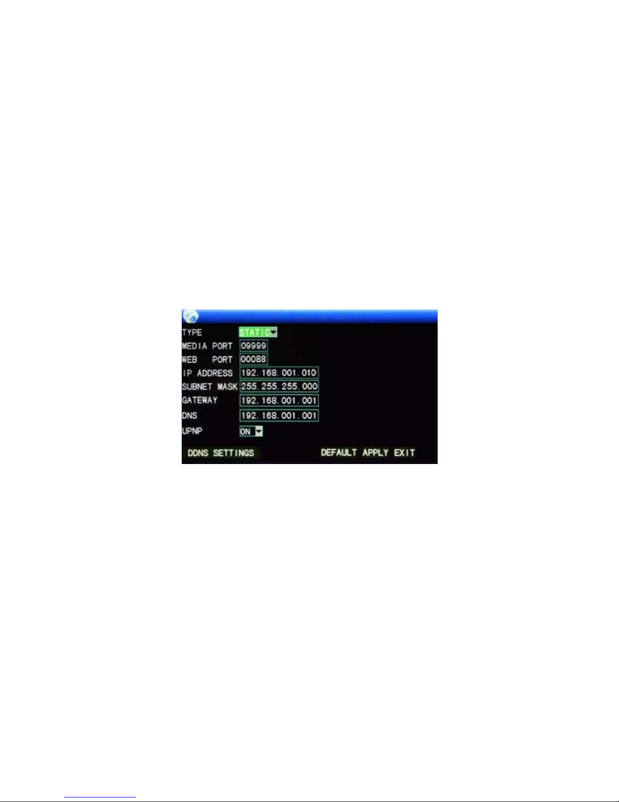
Press “MENU” on the DVR front panel to bring up the main menu. Select “ADVANCED” “NETWORK”
to set the Static IP address.
Choose “Static” to allocate an IP address manually, and then enter the IP Address, Subnet mask, and
Gateway.
For Example we have used:
IP Address: 192.168.1.10
Subnet: 255.255.255.0
Gateway: 192.168.1.1
DNS: 192.168.1.1
Should you wish to set your DVR up for internet access, you will require:
• An ADSL connection of 512/512 minimum (ADSL2 recommended).
• A static IP address from your Internet Service Provider.
• An ADSL Modem which supports Port Forwarding.
• A network connection between your DVR and the ADSL Modem.
• A good understanding of computer networks, this includes ‘Pinging a Device’, ‘IP Addresses’ and
‘Port Forwarding’. If you are unfamiliar with these procedures, you will need an I.T. person to
perform the work for you.
Page 12
11
KMeye Mobile App
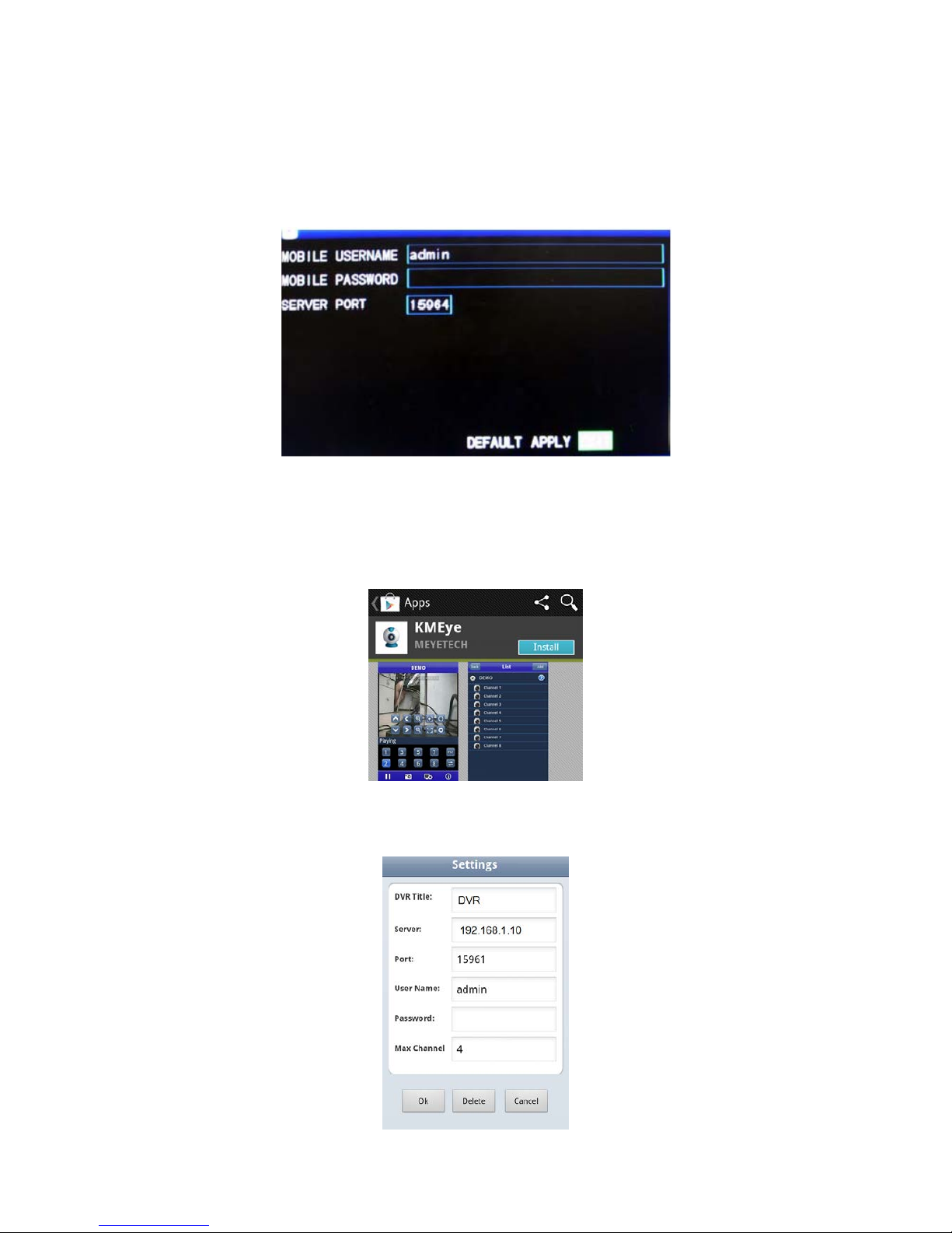
Press “MENU” on the DVR front panel to bring up the main menu. Select “ADVANCED” “MOBILE” to
set the Mobile access details.
This will allow you to set the username, password and port for the KMeye Mobile App.
To download the KMeye App
From your compatible Smartphone Access the App store or Market and download the free
“KMeye” App.
Once KMeye is installed, simply add the Name, IP Address port, user name and password of
your DVR. Then choose OK to save.
Page 13

12
TROUBLESHOOTING
Please refer to the FAQ table below for easy troubleshooting. The table below describes some
typical problems and their solutions. Please consult these guides before contacting your DVR
dealer.
PROBLEM
SOLUTION
No power
- Check power cord connection.
- Confirm that there is power from the outlet.
- Ensure that the 12V 3A power supply is connected to
the cameras and DVR.
Not working when pressing any button
- Press any key and then enter the password to exit
“Key Lock” mode.
Timer record function is not working
- Check if the “TIMER RECORD ENABLE” is set to
“YES”.
No live video
- Check the camera’s video cable and connections.
- Check the monitor’s video cable and connections.
- Ensure that the 12V 3A power supply is connected to
the cameras and the 12V 5A is connected to the DVR
No recorded video - Check if the HDD is installed and connected properly.
DVR keeps rebooting
- Ensure that the 12V 3A power supply is connected to
the cameras and DVR.
HDD detection failed
- Ensure that the 12V 3A power supply is connected to
the cameras and DVR.
Can’t detect your USB flash drive
- Test another USB flash drive.
- Ensure the USB is in FAT32 Format.
Can’t view the DVR images over the
network with web browser
- Update the JAVA program
- Update the firmware of the software Client
Can’t play the recorded data on my DVR
- There must be at least 8192 images of recorded data
for playback to work properly. If not, your DVR will
stop the playback.
- For example, if the IPS is set to 25, the recording time
should be at least 327 seconds (8192 images/25 IPS)
for the playback to work properly.
This guide is intended as a Quick Set Up and Basic use manual only, please refer to the
user manual on the included CD for all other details.
Page 14

13
Limited Warranty
Cornick Pty Ltd (Seller) warrants its products to be in conformance with its own plans and specifications and to be free from
defects in materials and workmanship under normal use and service for twenty four months from the date of or iginal p urchase.
Seller’s obligation shall be limited to repairing or replacing, at its option, free of charge for materials or labor, any part which is
proved not in compliance with Sellers specifications or proves defective in materials or workmanship under normal use and
service. Seller shall have no obligation under this Limited Warranty or otherwise if the product is altered or improperly repaired
or serviced by anyone other than Seller.
For Warranty Service: Return transportation prepaid with a copy of your purchase receipt and contact details to:
RhinoCo Technology, 9 Hannabus Place, McGraths Hill, NSW 2756 Australia.
Seller has no obligation to attend the buyer’s location to retrieve the goods or make repairs onsite.
• There are no warranties, expressed or implied, of merchant ability, or fitness for a particular purpose or otherwise, which
extend beyond the description on the face hereof. In no case shall seller be liable to anyone for any consequential or
incidental damages for breach of this or any other warranty, express or implied, or upon any other basis of liability
whatsoever, even the loss or damage is caused by its own negligence or fault.
• Seller does not represent that the products it sells may not be compromised or circumvented; that the products will prevent
any personal injury or property loss by burglary, robbery, fire or otherwise; or that the products will in all cases provide
adequate warning or protection. Customer understands that a properly installed and maintained alarm system or video
surveillance system may only reduce the risk of a burglary, robbery, or fire without warning, but it is not insurance or a
guarantee that such will not occur or that there will be no personal injury or property loss as a result.
• Consequently, seller shall have no liability for any personal injury; property damage or other loss based on a claim the
product failed to give any warning. However, if seller is held liable, whether directly or indirectly, for any loss or damage
arising under this limited warranty or otherwise, regard less of cause or origin, seller's maximum liability shall not in any
case exceed the purchase price of the product, which shall be the complete and exclusive remedy against seller.
• This warranty replaces any previous warranties and is the only warranty made by the Seller on this product. No increase or
alteration, written or verbal, of the obligations of this Limited Warranty is authorised.
Please refer to the website (www.watchguardalarms.com.au
) for a full list of trading terms.
Page 15
14
PLEASE CUT OUT & RETURN THIS INFORMATION
WITHIN 14 DAY S OF PURCHASE TO:
RhinoCo Technology
9 Hannabus Place
McGraths Hill NSW 2756 Australia
Model:DVR4/8EONPACK
Professional Surveillance Pack Warranty Card
Name
Address
Suburb
State
Postcode
Email
Date of Purchase
Invoice Number
Daytime Phone
Model of DVR System: DVR4EONPACK or DVR8EONPACK
Where did you purchase your DVR System?
Store Location
Dear Customer,
We appreciate your confidence in our product, and you can be certain that we will do everything possible to ensure
that you are happy with your decision and that you have years of satisfaction from your DVR System.
We take extreme care in the research, design and development of our products to ensure they meet your needs.
Additionally, we keep in close contact with our dealers Australia wide, and should any problem occur, we will work
closely with your local dealer to see that it is resolved quickly.
As a leading designer and manufacturer, we are continually endeavouring to exceed the expectations of our
customers. Furthermore, we appreciate your input regarding potential design improvements, issues regarding our
service and support, and any other ideas you may have which could help us to serve you better.
Please make any comments you have here:
 Loading...